EP0593821A1 - Farbbandverpackung zum Nachladen einer nachladbaren Kassette eines Thermodruckers - Google Patents
Farbbandverpackung zum Nachladen einer nachladbaren Kassette eines Thermodruckers Download PDFInfo
- Publication number
- EP0593821A1 EP0593821A1 EP92203247A EP92203247A EP0593821A1 EP 0593821 A1 EP0593821 A1 EP 0593821A1 EP 92203247 A EP92203247 A EP 92203247A EP 92203247 A EP92203247 A EP 92203247A EP 0593821 A1 EP0593821 A1 EP 0593821A1
- Authority
- EP
- European Patent Office
- Prior art keywords
- spool
- package
- cassette
- spools
- ribbon
- Prior art date
- Legal status (The legal status is an assumption and is not a legal conclusion. Google has not performed a legal analysis and makes no representation as to the accuracy of the status listed.)
- Granted
Links
Images


Classifications
-
- B—PERFORMING OPERATIONS; TRANSPORTING
- B41—PRINTING; LINING MACHINES; TYPEWRITERS; STAMPS
- B41J—TYPEWRITERS; SELECTIVE PRINTING MECHANISMS, i.e. MECHANISMS PRINTING OTHERWISE THAN FROM A FORME; CORRECTION OF TYPOGRAPHICAL ERRORS
- B41J17/00—Mechanisms for manipulating page-width impression-transfer material, e.g. carbon paper
- B41J17/32—Detachable carriers or holders for impression-transfer material mechanism
-
- B—PERFORMING OPERATIONS; TRANSPORTING
- B65—CONVEYING; PACKING; STORING; HANDLING THIN OR FILAMENTARY MATERIAL
- B65D—CONTAINERS FOR STORAGE OR TRANSPORT OF ARTICLES OR MATERIALS, e.g. BAGS, BARRELS, BOTTLES, BOXES, CANS, CARTONS, CRATES, DRUMS, JARS, TANKS, HOPPERS, FORWARDING CONTAINERS; ACCESSORIES, CLOSURES, OR FITTINGS THEREFOR; PACKAGING ELEMENTS; PACKAGES
- B65D85/00—Containers, packaging elements or packages, specially adapted for particular articles or materials
- B65D85/67—Containers, packaging elements or packages, specially adapted for particular articles or materials for web or tape-like material
- B65D85/671—Containers, packaging elements or packages, specially adapted for particular articles or materials for web or tape-like material wound in flat spiral form
- B65D85/672—Containers, packaging elements or packages, specially adapted for particular articles or materials for web or tape-like material wound in flat spiral form on cores
Definitions
- the present invention relates to a dye ribbon package for use with a thermal printer which comprises a supply spool with a roll of dye ribbon wound thereon and a take-up spool having the leading end of the dye ribbon attached thereto, and to a method of loading the reloadable cassette of a thermal printer with the dye ribbon from the described package.
- a dye ribbon in the form of a web-type dye-carrier containing a series of spaced frames of different coloured heat transferable dyes is spooled on a supply spool.
- the ribbon is paid out from the supply spool and rewound on a take-up spool.
- the ribbon moves through a nip formed between a thermal print head and a dye-absorbing receiver sheet.
- the receiver sheet may, for example, be coated on synthetic paper and the print head is formed of a plurality of heating elements.
- cassettes are made from plastic and are of the disposable type so that convenience for the operator of the printer is high. Since environmental considerations are putting an ever increasing strain on the use of disposable cassettes, there is a recent trend to use reloadable cassettes. These reloadable cassettes have basically the same configuration as the original dedicated ones but have a two part construction allowing the operator to open them and to load them with a supply spool with a roll of fresh dye ribbon and an empty take up spool. The loaded cassette is then put in the printer in the same way as an original disposable cassette.
- a dye ribbon package for use with a thermal printer which comprises a supply spool with a roll of dye ribbon wound thereon and a take-up spool having the leading end of the dye ribbon attached thereto for rewinding the ribbon as it is paid of from the supply spool, is characterized thereby that it includes a bottom wall and two upstanding opposed lateral wall means having opposed slotlike openings for engagement with the corresponding ends of the cores of the spools thereby to support both spools in parallel relationship, said slotlike openings allowing easy removal of the spools from the package in a direction radial to their axis, and the slotlike openings being open at their lateral outside surface thereby allowing gripping of the front ends of the spools by an operator's fingers.
- the inventive package forms so to say a loading aid for transferring the spools with the ribbon from their initial wrapping into the cassette of a printer.
- a direct transfer of the ribbon and the spools into a printer is theoretically feasable but practically uninteresting since locating the ribbon and spools in a cassette allows easy removal of them from the printer in the case of ribbon or receiver jam or any other defect requiring removal of the ribbon from the printer, or for replacing a colour ribbon by a black and white ribbon.
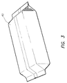
- the package can be made from any suitable material that readily lends itself to an economic and ecologically disposable wrapper, e.g. corrugated board, either paper, or plastic such as polypropylene board, which has been cut into the correct blank size and creased to produce a folding carton that constitutes the wrapping box.
- suitable material that readily lends itself to an economic and ecologically disposable wrapper, e.g. corrugated board, either paper, or plastic such as polypropylene board, which has been cut into the correct blank size and creased to produce a folding carton that constitutes the wrapping box.
- each of the side wall means of the package comprises two wall sections, namely an innerside wall section co-operating with flanges on the spools as described hereinbefore, and outside wall sections running obliquely outwardly from the top of the innerside sections towards the bottom of the package.
- This configuration has the advantage of an improved stiffness in a transverse plane, and of an improved accessibility of the front ends of the spools.
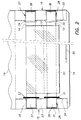
- a package 10 in accordance with the invention comprises a supply spool 12 with a roll of dye ribbon 13 wound thereon and a take-up spool 14 to which the leading end of the dye ribbon is attached for rewinding the ribbon as it is paid of from the supply spool.
- the package 10 is formed from a sheet of corrugated paper board which has been appropriately cut and creased to allow it to be folded for obtaining a construction as shown in the figure.
- the package comprises a base portion with a bottom wall 11 and two opposed upstanding lateral walls 15 and 16, and a cover 17 comprising three panels 18, 19 and 20 which are hingedly connected together, panel 18 being hingedly connected to bottom wall 11.
- Walls 15 and 16 are formed by wall sections folded in the form of an inverted U, as shown by wall sections 21, 23 and 24 for wall 15, sections 21 and 24 running parallel with each other.
- Each of the walls 15 and 16 has two vertical slotlike openings, viz. 25, 26 and 27, 28 that are formed by cut-away portions of the paper board.
- Such larger flanges can have a knurled rim for improved frictional engagement, as shown for flanges 31 and 33.
- the width of the ribbon is smaller than the distance separating both flanges of each spool 10, so that frictional contact with the lateral edges of the ribbon is avoided.
- the core ends 35, 36, 37 and 38 of the spools fit in the corresponding slotlike openings of lateral walls 15 and 17 with a slight clearance, and their length is such that if a spool flange abuts a lateral wall, the corresponding front end of the spool still does not protrude beyond the package.
- the ends of the spools may be appropriately shaped for being engaged by driving and journalling spindles of a thermal printer.
- the core ends may have opposed slots such as 39 shown in Fig. 4, for engagement by radial pins of a driving spindle.
- the core ends may have a square or otherwise shaped central opening for engagement with a driving spindle, or the front ends may have a toothed rim for engagement by a correspondingly toothed collar on the driving spindle of a printer.
- the spools may have a gear wheel for co-operation with a corresponding gear in a thermal printer.
- Suchlike gear wheel can replace the knurled flanges such as 31 and 33.
- a suitable wrapping foil may be a laminate of a vacuum -metallised polyester foil and a black-pigmented polyethylene foil, which allows heat sealing of the wrapping.
- the wrapping foil is removed from the package and the opened package is located in front of an empty cassette 41 on a desk.
- the cassette is a frame-like supporting structure which has slotlike openings in its lateral walls for receiving the core ends of the spools.
- the cassette shown in the figure is basically a traylike construction 42 with a large square opening in the bottom allowing a thermal printing head to urge the ribbon in contact with a receiver sheet under the cassette.
- the lateral walls of the cassette have slotlike openings 43, 44, 45 and 46 formed by resilient clips or the like, allowing insertion of the spool ends in the openings under a slight force and maintaining such ends in position during manipulations for placing the cassette in the printer.
- the entry end of the clip means has an opening width smaller than the diameter of the core ends of the spools, whereas the central area of said clip means has a width larger than the diameter of said core ends thereby to allow appropriate centering of the spools by spindles of the printer entering in driving engagement with the spool ends after the cassette has been placed in the printer.
- the spool which is nearest to the cassette, in the present case spool 12, is gripped by the operator with his fingertips at the front ends which are freely accessible at the outerside of the lateral walls 15 and 16 of the package, and then lifted and taken out, as indicated by the arrows 47 and 48 in order to locate it in the openings 43 and 45 of cassette 41.
- the spool of the package which is most remote from the cassette i.e. spool 14 is taken out and loaded in the cassette along a path indicated by the arrows 50, 51 at the position which is most remote from the package, i.e. in the openings 44 and 46.
- the loaded cassette can now be placed in a thermal printer, and after the spools have been drivingly engaged by driving pins of the apparatus, printing can start.
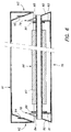
- FIG. 4 A most stripped form of reloadable cassette which can be used in the method according to the invention is shown in Figs. 4 and 5.
- the cassette 52 consists basically of two flanges 53 and 54 spaced in parallel relationship by five rods 56 to 60.
- the flanges are made of sheet metal whereas the rods are solid and tapped at their ends to allow their fixing to the flanges by screws.
- the flanges have outwardly angled portions 61 and 62 forming handles allowing easy gripping of the frame.
- the size of a full dye ribbon roll has been illustrated in dot-and-dash lines.
- the supports for the spools are formed by four elastic clips 63 to 66 fitted to the flanges of the frame by a screw-and-nut connection, as shown by screw 67 and nut 68 for clip 63.
- the clips are suitably made of a resilient plastic and have rather long legs requiring but a limited force for the insertion of the spool ends in the clips.
- the spool ends are journalled with sufficient play in the curved portions of the legs of the clips to allow their precise radial centering by the driving spindles of the thermal printer, as known in the art.
- the cassette 52 rests in the thermal printer on two supporting rods 69 and 70.
- the position of the drum of the printer which bears the receiving sheet is indicated in broken lines 71.
- the cassette has an idler roller 72 for conveying the dye ribbon 55 unwound from supply spool 74 along the required path to the take-up spool 73.
- An idler roller 77 belongs to the lid of the thermal printer and in the closed position of the lid occupies a position as illustrated thereby to convey the ribbon closely past drum 71.
- the hinged cover can have side walls overlapping the side walls of the base thereby to close the outside of the slotlike openings in view of an improved protection of the spool ends during manipulation of the package.
- a base 76 is formed from a blank of corrugated board cut and folded to produce two lateral walls 78 and 79 each consisting of wall sections 80, 81 and 82,83 forming upstanding triangular configurations with cut-out slots 84 and 85 simalar to slots 25 to 28 of Fig. 1.
- a spool 86 with a roll of ribbon 87 is journalled with its ends in the slots, and flanges 89 and 90 ensure the axial position of the spool by co-operating with the innerside wall sections 81 and 83.
- Hinging cover 91 has been shown in slightly lifted position for the sake of clarity, and has equally two lateral walls 92 and 93 with a triangular shape fitting closely over the corresponding walls of the base in the closed position of the cover.
- the innerside sections of walls 92 and 93 may have tongues such as 94 and 95 formed by appropriate cuts and are urged away by contact with the front ends of the spool as the cover is closed. The frictional engagement of the tongues with the core avoids clockspringing of the spool.
- the package can be provided with other means, known on themselves, for preventing clockspringing unwinding of the supply spool during manipulations of the package.
- Suchklike means can co-operate with the flange(s) of the spool(s) or occasionally with gearwheels making part of the spools.
- the package can be formed from a sheet of corrugated polypropylene board instead of from paper board.
- a loaded cassette can be stored in a suitable storage box in case if not in use in a printer. This may be the case e.g. when several cassettes are loaded at a time in order to have them instantly available for printing.
Landscapes
- Engineering & Computer Science (AREA)
- Mechanical Engineering (AREA)
- Impression-Transfer Materials And Handling Thereof (AREA)
- Packaging Of Machine Parts And Wound Products (AREA)
- Electronic Switches (AREA)
Priority Applications (4)
| Application Number | Priority Date | Filing Date | Title |
|---|---|---|---|
| DE69217058T DE69217058T2 (de) | 1992-10-22 | 1992-10-22 | Farbbandverpackung zum Nachladen einer nachladbaren Kassette eines Thermodruckers |
| EP92203247A EP0593821B1 (de) | 1992-10-22 | 1992-10-22 | Farbbandverpackung zum Nachladen einer nachladbaren Kassette eines Thermodruckers |
| US08/136,267 US5415486A (en) | 1992-10-22 | 1993-10-15 | Dye ribbon package for use with a thermal printer and a method of loading the reloadable cassette of a thermal printer with a dye ribbon from a dye ribbon package |
| JP5287617A JPH06320764A (ja) | 1992-10-22 | 1993-10-22 | 熱プリンターと使用するための染料リボン・パッケージおよび熱プリンターの再装填式カセットに染料リボン・パッケージからのリボンを装填する方法 |
Applications Claiming Priority (1)
| Application Number | Priority Date | Filing Date | Title |
|---|---|---|---|
| EP92203247A EP0593821B1 (de) | 1992-10-22 | 1992-10-22 | Farbbandverpackung zum Nachladen einer nachladbaren Kassette eines Thermodruckers |
Publications (2)
| Publication Number | Publication Date |
|---|---|
| EP0593821A1 true EP0593821A1 (de) | 1994-04-27 |
| EP0593821B1 EP0593821B1 (de) | 1997-01-22 |
Family
ID=8210988
Family Applications (1)
| Application Number | Title | Priority Date | Filing Date |
|---|---|---|---|
| EP92203247A Expired - Lifetime EP0593821B1 (de) | 1992-10-22 | 1992-10-22 | Farbbandverpackung zum Nachladen einer nachladbaren Kassette eines Thermodruckers |
Country Status (4)
| Country | Link |
|---|---|
| US (1) | US5415486A (de) |
| EP (1) | EP0593821B1 (de) |
| JP (1) | JPH06320764A (de) |
| DE (1) | DE69217058T2 (de) |
Cited By (10)
| Publication number | Priority date | Publication date | Assignee | Title |
|---|---|---|---|---|
| FR2713552A1 (fr) * | 1993-12-15 | 1995-06-16 | Sagem | Sabot de chargement de ruban encreur pour imprimante à impression par transfert thermique. |
| WO1995020490A1 (en) * | 1994-01-27 | 1995-08-03 | Imperial Chemical Industries Plc | Thermal transfer ribbon cassette system |
| EP0679524A1 (de) * | 1994-04-29 | 1995-11-02 | Agfa-Gevaert N.V. | Kassetten-, Speicherdose für einen thermischen Drucker |
| DE4442511A1 (de) * | 1994-11-30 | 1996-06-05 | Esselte Meto Int Gmbh | Verfahren und Vorrichtung zum Einlegen eines Farbbandes in einen Drucker |
| EP0931672A1 (de) * | 1998-01-06 | 1999-07-28 | Brother Kogyo Kabushiki Kaisha | Farbbandkassette |
| US6595710B2 (en) | 2000-03-31 | 2003-07-22 | Brother Kogyo Kabushiki Kaisha | Image forming device and ink sheet cartridge mounted on the image forming device |
| US6715946B2 (en) | 1998-01-06 | 2004-04-06 | Brother Kogyo Kabushiki Kaisha | Ink ribbon cartridge and printing device |
| US6991388B2 (en) | 1998-01-06 | 2006-01-31 | Brother Kogyo Kabushiki Kaisha | Ink ribbon cartridge having takeup-side cover with opening positioned beneath protrusion in cover |
| USRE39169E1 (en) | 1997-01-06 | 2006-07-11 | Brother Kogyo Kabushiki Kaisha | Ink ribbon cartridge having a particular spool and spindle arrangement |
| EP1657069A3 (de) * | 2004-11-16 | 2009-09-09 | Sagem Communications | Verbrauchsgut für Druckvorrichtung mit U-förmigem Halter und geeigneter Behälter |
Families Citing this family (26)
| Publication number | Priority date | Publication date | Assignee | Title |
|---|---|---|---|---|
| JPH07186476A (ja) * | 1993-12-28 | 1995-07-25 | Sony Corp | リボンカートリッジ |
| JP3433539B2 (ja) * | 1994-06-20 | 2003-08-04 | ソニー株式会社 | プリンタのインクリボンユニット |
| US5713179A (en) * | 1994-09-30 | 1998-02-03 | Dai Nippon Printing Co. Ltd. | Combination of sheet roll with subshaft, producing apparatus thereof, packaging apparatus thereof, and production system thereof |
| US5547298A (en) * | 1995-06-28 | 1996-08-20 | Agfa-Gevaert N. V. | Dye ribbon package for thermal printers |
| FR2744392B1 (fr) * | 1996-02-02 | 1998-03-06 | Sagem | Recharge de film encreur pour imprimante a transfert thermique |
| JPH09315433A (ja) * | 1996-05-24 | 1997-12-09 | Zeon Kasei Co Ltd | ロール製品輸送用コンテナ |
| JP3721684B2 (ja) * | 1997-01-07 | 2005-11-30 | ブラザー工業株式会社 | 印字装置及びファクシミリ装置 |
| US5978005A (en) * | 1998-04-03 | 1999-11-02 | Eastman Kodak Company | Thermal printer and method for detecting donor ribbon type and for aligning color patches relative to a print head |
| US6428221B1 (en) | 1999-07-16 | 2002-08-06 | International Imaging Materials, Inc. | Package with web roll and take-up core |
| US6224277B1 (en) | 1999-07-16 | 2001-05-01 | International Imaging Materials, Inc. | Ink ribbon with adhesive for attaching end of ribbon to supply roll |
| JP2002029127A (ja) * | 2000-07-13 | 2002-01-29 | Mitsubishi Electric Corp | インクカセット、インクリボン供給容器及びインクリボンのインクカセットへの取り付け方法 |
| EP1221379B1 (de) * | 2000-07-13 | 2007-06-27 | Olympus Optical Co., Ltd. | Verfahren zur einführung eines austauschfarbbandes |
| US6509919B1 (en) | 2000-09-01 | 2003-01-21 | Eastman Kodak Company | Apparatus adapted to sense a colorant and method for sensing color and detecting a donor mispick condition |
| US6682241B2 (en) | 2002-02-21 | 2004-01-27 | Eastman Kodak Company | Thermal printer with loading aid |
| US7934881B2 (en) * | 2003-10-20 | 2011-05-03 | Zih Corp. | Replaceable ribbon supply and substrate cleaning apparatus |
| US20050084315A1 (en) * | 2003-10-20 | 2005-04-21 | Zebra Technologies Corporation | Substrate cleaning apparatus and method |
| US20050127083A1 (en) * | 2003-11-04 | 2005-06-16 | Russell Stephan E. | Gift wrap storage container |
| US7186042B2 (en) | 2004-01-21 | 2007-03-06 | Silverbrook Research Pty Ltd | Wallpaper printer |
| US20060159505A1 (en) * | 2004-12-10 | 2006-07-20 | Robert Holmberg | Ribbon packaging and loading device |
| EP2075198B1 (de) * | 2007-12-26 | 2011-04-20 | Dai Nippon Printing Co., Ltd. | Verpackung |
| GB2504075A (en) | 2012-07-16 | 2014-01-22 | Nicoventures Holdings Ltd | Electronic smoking device |
| GB2504076A (en) | 2012-07-16 | 2014-01-22 | Nicoventures Holdings Ltd | Electronic smoking device |
| GB201505597D0 (en) | 2015-03-31 | 2015-05-13 | British American Tobacco Co | Article for use with apparatus for heating smokable material |
| GB201505595D0 (en) | 2015-03-31 | 2015-05-13 | British American Tobacco Co | Cartridge for use with apparatus for heating smokeable material |
| JP6880643B2 (ja) * | 2016-10-19 | 2021-06-02 | カシオ計算機株式会社 | 印刷装置 |
| KR200497172Y1 (ko) * | 2019-11-13 | 2023-08-18 | 에스케이넥실리스 주식회사 | 동박용 수납장치 |
Citations (3)
| Publication number | Priority date | Publication date | Assignee | Title |
|---|---|---|---|---|
| US3332546A (en) * | 1965-06-24 | 1967-07-25 | Franklin Container Corp | Protective shipping and storage container |
| US3520409A (en) * | 1969-03-10 | 1970-07-14 | Johnson & Johnson | Package |
| DE4035598A1 (de) * | 1990-11-06 | 1992-05-07 | Siemens Ag | Farbbandvorratseinrichtung |
Family Cites Families (7)
| Publication number | Priority date | Publication date | Assignee | Title |
|---|---|---|---|---|
| US3530980A (en) * | 1968-09-20 | 1970-09-29 | Johnson & Johnson | Package |
| US4151914A (en) * | 1978-07-24 | 1979-05-01 | Franklin Container Corporation | Shipping and storage container for rolls |
| JPS62213180A (ja) * | 1986-03-13 | 1987-09-19 | Nec Corp | ジヨセフソン接合素子の製造方法 |
| JPS62213181A (ja) * | 1986-03-14 | 1987-09-19 | Toshiba Corp | Co2ガスレ−ザ装置 |
| JPS63283971A (ja) * | 1987-05-16 | 1988-11-21 | Hitachi Maxell Ltd | 感熱転写体用カ−トリッジ |
| JPH01286876A (ja) * | 1989-03-15 | 1989-11-17 | Toshiba Corp | インクフィルム装置 |
| DE69130367T2 (de) * | 1990-03-30 | 1999-04-01 | Kabushiki Kaisha Tec, Shizuoka | Transferdrucker |
-
1992
- 1992-10-22 DE DE69217058T patent/DE69217058T2/de not_active Expired - Fee Related
- 1992-10-22 EP EP92203247A patent/EP0593821B1/de not_active Expired - Lifetime
-
1993
- 1993-10-15 US US08/136,267 patent/US5415486A/en not_active Expired - Fee Related
- 1993-10-22 JP JP5287617A patent/JPH06320764A/ja active Pending
Patent Citations (3)
| Publication number | Priority date | Publication date | Assignee | Title |
|---|---|---|---|---|
| US3332546A (en) * | 1965-06-24 | 1967-07-25 | Franklin Container Corp | Protective shipping and storage container |
| US3520409A (en) * | 1969-03-10 | 1970-07-14 | Johnson & Johnson | Package |
| DE4035598A1 (de) * | 1990-11-06 | 1992-05-07 | Siemens Ag | Farbbandvorratseinrichtung |
Non-Patent Citations (1)
| Title |
|---|
| PATENT ABSTRACTS OF JAPAN vol. 11, no. 50 (M-562)17 February 1987 & JP-A-61 213 181 ( MITSUBISHI ELECTRIC ) * |
Cited By (23)
| Publication number | Priority date | Publication date | Assignee | Title |
|---|---|---|---|---|
| FR2713552A1 (fr) * | 1993-12-15 | 1995-06-16 | Sagem | Sabot de chargement de ruban encreur pour imprimante à impression par transfert thermique. |
| EP0658435A1 (de) * | 1993-12-15 | 1995-06-21 | SOCIETE D'APPLICATIONS GENERALES D'ELECTRICITE ET DE MECANIQUE SAGEM Société anonyme française | Übertragungsbandkassette für einen Wärmeübertragungsdrucker |
| US5605403A (en) * | 1993-12-15 | 1997-02-25 | Societe D'applications Generales D'electricite Et De Mechanique Sagem | Inking ribbon loading shoe for a printer with thermal transfer printing |
| WO1995020490A1 (en) * | 1994-01-27 | 1995-08-03 | Imperial Chemical Industries Plc | Thermal transfer ribbon cassette system |
| EP0679524A1 (de) * | 1994-04-29 | 1995-11-02 | Agfa-Gevaert N.V. | Kassetten-, Speicherdose für einen thermischen Drucker |
| DE4442511A1 (de) * | 1994-11-30 | 1996-06-05 | Esselte Meto Int Gmbh | Verfahren und Vorrichtung zum Einlegen eines Farbbandes in einen Drucker |
| WO1996016814A1 (de) * | 1994-11-30 | 1996-06-06 | Esselte Meto International Gmbh | Vorrichtung zum einlegen eines farbbandes in einen drucker |
| USRE41064E1 (en) | 1997-01-06 | 2009-12-29 | Brother Kogyo Kabushiki Kaisha | Ink ribbon cartridge having a particular spool and spindle arrangement |
| USRE39169E1 (en) | 1997-01-06 | 2006-07-11 | Brother Kogyo Kabushiki Kaisha | Ink ribbon cartridge having a particular spool and spindle arrangement |
| US6991388B2 (en) | 1998-01-06 | 2006-01-31 | Brother Kogyo Kabushiki Kaisha | Ink ribbon cartridge having takeup-side cover with opening positioned beneath protrusion in cover |
| EP1000765A3 (de) * | 1998-01-06 | 2000-08-02 | Brother Kogyo Kabushiki Kaisha | Farbbandkassette |
| EP0931672A1 (de) * | 1998-01-06 | 1999-07-28 | Brother Kogyo Kabushiki Kaisha | Farbbandkassette |
| US6623192B1 (en) | 1998-01-06 | 2003-09-23 | Brother Kogyo Kabushiki Kaisha | Ink ribbon cartridge having protrusion and recessed portion |
| US6715946B2 (en) | 1998-01-06 | 2004-04-06 | Brother Kogyo Kabushiki Kaisha | Ink ribbon cartridge and printing device |
| US6257780B1 (en) | 1998-01-06 | 2001-07-10 | Brother Kogyo Kabushiki Kaisha | Ink ribbon cartridge having one undetachable spool and idle rotation preventing structure |
| US6827510B2 (en) | 2000-03-31 | 2004-12-07 | Brother Kogyo Kabushiki Kaisha | Ink sheet cartridge having partitioning plate including at least two symmetrically positioned recesses |
| US6595710B2 (en) | 2000-03-31 | 2003-07-22 | Brother Kogyo Kabushiki Kaisha | Image forming device and ink sheet cartridge mounted on the image forming device |
| US7079167B2 (en) | 2000-03-31 | 2006-07-18 | Brother Kogyo Kabushiki Kaisha | Ink sheet cartridge and exchangeable ink-sheet set mounted on the ink sheet cartridge |
| US7102659B2 (en) | 2000-03-31 | 2006-09-05 | Brother Kogyo Kabushiki Kaisha | Ink sheet cartridge and exchangeable ink-sheet set mounted on the ink sheet cartridge |
| US7367727B2 (en) | 2000-03-31 | 2008-05-06 | Brother Kogyo Kabushiki Kaisha | Ink sheet cartridge having paper guide |
| US6621510B2 (en) | 2000-03-31 | 2003-09-16 | Brother Kogyo Kabushiki Kaisha | Ink sheet cartridge and exchangeable ink-sheet set mounted on the ink sheet cartridge |
| US7758263B2 (en) | 2000-03-31 | 2010-07-20 | Brother Kogyo Kabushiki Kaisha | Ink ribbon cartridge having projections extending from connecting members |
| EP1657069A3 (de) * | 2004-11-16 | 2009-09-09 | Sagem Communications | Verbrauchsgut für Druckvorrichtung mit U-förmigem Halter und geeigneter Behälter |
Also Published As
| Publication number | Publication date |
|---|---|
| DE69217058D1 (de) | 1997-03-06 |
| US5415486A (en) | 1995-05-16 |
| DE69217058T2 (de) | 1997-06-26 |
| JPH06320764A (ja) | 1994-11-22 |
| EP0593821B1 (de) | 1997-01-22 |
Similar Documents
| Publication | Publication Date | Title |
|---|---|---|
| EP0593821B1 (de) | Farbbandverpackung zum Nachladen einer nachladbaren Kassette eines Thermodruckers | |
| US6561506B2 (en) | Recording sheet package and sheet supply cassette for printer | |
| US5547298A (en) | Dye ribbon package for thermal printers | |
| US6318918B1 (en) | Recording sheet package for use with printer, and recording sheet supplying method | |
| JPH0480374B2 (de) | ||
| US11241896B2 (en) | Housing case and tape ribbon set | |
| US5605403A (en) | Inking ribbon loading shoe for a printer with thermal transfer printing | |
| US4240757A (en) | Fanfold replacement ribbon package | |
| US5433540A (en) | Combined spool retainer and installation device | |
| US5536094A (en) | Protective ink ribbon unit holder | |
| US4165807A (en) | Tape-mounted electronic component package | |
| JPS63247257A (ja) | 新聞、雑誌等の巻き取った印刷物を中間貯蔵する巻取物支持体 | |
| US4715500A (en) | Light-sensitive photographic film packaging | |
| EP0477776B1 (de) | Universelle Verpackung zur Verwendung in unterschiedlichen Geräten | |
| EP0477777B1 (de) | Träger für Filmpackung | |
| EP1221379B1 (de) | Verfahren zur einführung eines austauschfarbbandes | |
| JP3805545B2 (ja) | 記録紙ロール用給紙マガジン | |
| JP2516609Y2 (ja) | インクフィルムロール用サイドホルダ | |
| JP3465448B2 (ja) | プリンタのインクリボンユニット用ホルダ | |
| JP4346762B2 (ja) | パックケース | |
| JPH056136Y2 (de) | ||
| JP3033283B2 (ja) | 熱転写記録装置及びそのインク紙装填方法 | |
| JP2000335065A (ja) | インクリボンパッケージ | |
| JPH10166698A (ja) | インクリボンの結束装置 | |
| JPH10100501A (ja) | 感熱記録装置 |
Legal Events
| Date | Code | Title | Description |
|---|---|---|---|
| PUAI | Public reference made under article 153(3) epc to a published international application that has entered the european phase |
Free format text: ORIGINAL CODE: 0009012 |
|
| AK | Designated contracting states |
Kind code of ref document: A1 Designated state(s): BE DE FR GB NL |
|
| 17P | Request for examination filed |
Effective date: 19940917 |
|
| 17Q | First examination report despatched |
Effective date: 19951106 |
|
| GRAG | Despatch of communication of intention to grant |
Free format text: ORIGINAL CODE: EPIDOS AGRA |
|
| GRAH | Despatch of communication of intention to grant a patent |
Free format text: ORIGINAL CODE: EPIDOS IGRA |
|
| GRAH | Despatch of communication of intention to grant a patent |
Free format text: ORIGINAL CODE: EPIDOS IGRA |
|
| GRAA | (expected) grant |
Free format text: ORIGINAL CODE: 0009210 |
|
| AK | Designated contracting states |
Kind code of ref document: B1 Designated state(s): BE DE FR GB NL |
|
| PG25 | Lapsed in a contracting state [announced via postgrant information from national office to epo] |
Ref country code: NL Free format text: LAPSE BECAUSE OF FAILURE TO SUBMIT A TRANSLATION OF THE DESCRIPTION OR TO PAY THE FEE WITHIN THE PRESCRIBED TIME-LIMIT Effective date: 19970122 Ref country code: FR Effective date: 19970122 Ref country code: BE Effective date: 19970122 |
|
| REF | Corresponds to: |
Ref document number: 69217058 Country of ref document: DE Date of ref document: 19970306 |
|
| EN | Fr: translation not filed | ||
| NLV1 | Nl: lapsed or annulled due to failure to fulfill the requirements of art. 29p and 29m of the patents act | ||
| PGFP | Annual fee paid to national office [announced via postgrant information from national office to epo] |
Ref country code: GB Payment date: 19970826 Year of fee payment: 6 |
|
| PLBE | No opposition filed within time limit |
Free format text: ORIGINAL CODE: 0009261 |
|
| REG | Reference to a national code |
Ref country code: GB Ref legal event code: 746 Effective date: 19971124 |
|
| 26N | No opposition filed | ||
| PG25 | Lapsed in a contracting state [announced via postgrant information from national office to epo] |
Ref country code: GB Free format text: LAPSE BECAUSE OF NON-PAYMENT OF DUE FEES Effective date: 19981022 |
|
| GBPC | Gb: european patent ceased through non-payment of renewal fee |
Effective date: 19981022 |
|
| PGFP | Annual fee paid to national office [announced via postgrant information from national office to epo] |
Ref country code: DE Payment date: 20000911 Year of fee payment: 9 |
|
| PG25 | Lapsed in a contracting state [announced via postgrant information from national office to epo] |
Ref country code: DE Free format text: LAPSE BECAUSE OF NON-PAYMENT OF DUE FEES Effective date: 20020702 |