EP0594110A2 - Farbstrahldruckkopf, dessen Herstellungsverfahren und zugehöriges Farbstrahlgerät - Google Patents
Farbstrahldruckkopf, dessen Herstellungsverfahren und zugehöriges Farbstrahlgerät Download PDFInfo
- Publication number
- EP0594110A2 EP0594110A2 EP93116807A EP93116807A EP0594110A2 EP 0594110 A2 EP0594110 A2 EP 0594110A2 EP 93116807 A EP93116807 A EP 93116807A EP 93116807 A EP93116807 A EP 93116807A EP 0594110 A2 EP0594110 A2 EP 0594110A2
- Authority
- EP
- European Patent Office
- Prior art keywords
- ink
- ink jet
- jet head
- paths
- base board
- Prior art date
- Legal status (The legal status is an assumption and is not a legal conclusion. Google has not performed a legal analysis and makes no representation as to the accuracy of the status listed.)
- Granted
Links
Images


Classifications
-
- B—PERFORMING OPERATIONS; TRANSPORTING
- B41—PRINTING; LINING MACHINES; TYPEWRITERS; STAMPS
- B41J—TYPEWRITERS; SELECTIVE PRINTING MECHANISMS, i.e. MECHANISMS PRINTING OTHERWISE THAN FROM A FORME; CORRECTION OF TYPOGRAPHICAL ERRORS
- B41J2/00—Typewriters or selective printing mechanisms characterised by the printing or marking process for which they are designed
- B41J2/005—Typewriters or selective printing mechanisms characterised by the printing or marking process for which they are designed characterised by bringing liquid or particles selectively into contact with a printing material
- B41J2/01—Ink jet
- B41J2/135—Nozzles
- B41J2/14—Structure thereof only for on-demand ink jet heads
- B41J2/14016—Structure of bubble jet print heads
- B41J2/14145—Structure of the manifold
-
- B—PERFORMING OPERATIONS; TRANSPORTING
- B41—PRINTING; LINING MACHINES; TYPEWRITERS; STAMPS
- B41J—TYPEWRITERS; SELECTIVE PRINTING MECHANISMS, i.e. MECHANISMS PRINTING OTHERWISE THAN FROM A FORME; CORRECTION OF TYPOGRAPHICAL ERRORS
- B41J2/00—Typewriters or selective printing mechanisms characterised by the printing or marking process for which they are designed
- B41J2/005—Typewriters or selective printing mechanisms characterised by the printing or marking process for which they are designed characterised by bringing liquid or particles selectively into contact with a printing material
- B41J2/01—Ink jet
- B41J2/135—Nozzles
- B41J2/16—Production of nozzles
- B41J2/1601—Production of bubble jet print heads
- B41J2/1604—Production of bubble jet print heads of the edge shooter type
-
- B—PERFORMING OPERATIONS; TRANSPORTING
- B41—PRINTING; LINING MACHINES; TYPEWRITERS; STAMPS
- B41J—TYPEWRITERS; SELECTIVE PRINTING MECHANISMS, i.e. MECHANISMS PRINTING OTHERWISE THAN FROM A FORME; CORRECTION OF TYPOGRAPHICAL ERRORS
- B41J2/00—Typewriters or selective printing mechanisms characterised by the printing or marking process for which they are designed
- B41J2/005—Typewriters or selective printing mechanisms characterised by the printing or marking process for which they are designed characterised by bringing liquid or particles selectively into contact with a printing material
- B41J2/01—Ink jet
- B41J2/135—Nozzles
- B41J2/16—Production of nozzles
- B41J2/1621—Manufacturing processes
- B41J2/1623—Manufacturing processes bonding and adhesion
-
- B—PERFORMING OPERATIONS; TRANSPORTING
- B41—PRINTING; LINING MACHINES; TYPEWRITERS; STAMPS
- B41J—TYPEWRITERS; SELECTIVE PRINTING MECHANISMS, i.e. MECHANISMS PRINTING OTHERWISE THAN FROM A FORME; CORRECTION OF TYPOGRAPHICAL ERRORS
- B41J2/00—Typewriters or selective printing mechanisms characterised by the printing or marking process for which they are designed
- B41J2/005—Typewriters or selective printing mechanisms characterised by the printing or marking process for which they are designed characterised by bringing liquid or particles selectively into contact with a printing material
- B41J2/01—Ink jet
- B41J2/135—Nozzles
- B41J2/16—Production of nozzles
- B41J2/1621—Manufacturing processes
- B41J2/1631—Manufacturing processes photolithography
-
- B—PERFORMING OPERATIONS; TRANSPORTING
- B41—PRINTING; LINING MACHINES; TYPEWRITERS; STAMPS
- B41J—TYPEWRITERS; SELECTIVE PRINTING MECHANISMS, i.e. MECHANISMS PRINTING OTHERWISE THAN FROM A FORME; CORRECTION OF TYPOGRAPHICAL ERRORS
- B41J2/00—Typewriters or selective printing mechanisms characterised by the printing or marking process for which they are designed
- B41J2/005—Typewriters or selective printing mechanisms characterised by the printing or marking process for which they are designed characterised by bringing liquid or particles selectively into contact with a printing material
- B41J2/01—Ink jet
- B41J2/135—Nozzles
- B41J2/16—Production of nozzles
- B41J2/1621—Manufacturing processes
- B41J2/1632—Manufacturing processes machining
-
- B—PERFORMING OPERATIONS; TRANSPORTING
- B41—PRINTING; LINING MACHINES; TYPEWRITERS; STAMPS
- B41J—TYPEWRITERS; SELECTIVE PRINTING MECHANISMS, i.e. MECHANISMS PRINTING OTHERWISE THAN FROM A FORME; CORRECTION OF TYPOGRAPHICAL ERRORS
- B41J2/00—Typewriters or selective printing mechanisms characterised by the printing or marking process for which they are designed
- B41J2/005—Typewriters or selective printing mechanisms characterised by the printing or marking process for which they are designed characterised by bringing liquid or particles selectively into contact with a printing material
- B41J2/01—Ink jet
- B41J2/135—Nozzles
- B41J2/16—Production of nozzles
- B41J2/1621—Manufacturing processes
- B41J2/1637—Manufacturing processes molding
-
- B—PERFORMING OPERATIONS; TRANSPORTING
- B41—PRINTING; LINING MACHINES; TYPEWRITERS; STAMPS
- B41J—TYPEWRITERS; SELECTIVE PRINTING MECHANISMS, i.e. MECHANISMS PRINTING OTHERWISE THAN FROM A FORME; CORRECTION OF TYPOGRAPHICAL ERRORS
- B41J2/00—Typewriters or selective printing mechanisms characterised by the printing or marking process for which they are designed
- B41J2/005—Typewriters or selective printing mechanisms characterised by the printing or marking process for which they are designed characterised by bringing liquid or particles selectively into contact with a printing material
- B41J2/01—Ink jet
- B41J2/135—Nozzles
- B41J2/16—Production of nozzles
- B41J2/1621—Manufacturing processes
- B41J2/164—Manufacturing processes thin film formation
- B41J2/1645—Manufacturing processes thin film formation thin film formation by spincoating
-
- B—PERFORMING OPERATIONS; TRANSPORTING
- B41—PRINTING; LINING MACHINES; TYPEWRITERS; STAMPS
- B41J—TYPEWRITERS; SELECTIVE PRINTING MECHANISMS, i.e. MECHANISMS PRINTING OTHERWISE THAN FROM A FORME; CORRECTION OF TYPOGRAPHICAL ERRORS
- B41J2/00—Typewriters or selective printing mechanisms characterised by the printing or marking process for which they are designed
- B41J2/005—Typewriters or selective printing mechanisms characterised by the printing or marking process for which they are designed characterised by bringing liquid or particles selectively into contact with a printing material
- B41J2/01—Ink jet
- B41J2/135—Nozzles
- B41J2/14—Structure thereof only for on-demand ink jet heads
- B41J2002/14403—Structure thereof only for on-demand ink jet heads including a filter
-
- B—PERFORMING OPERATIONS; TRANSPORTING
- B41—PRINTING; LINING MACHINES; TYPEWRITERS; STAMPS
- B41J—TYPEWRITERS; SELECTIVE PRINTING MECHANISMS, i.e. MECHANISMS PRINTING OTHERWISE THAN FROM A FORME; CORRECTION OF TYPOGRAPHICAL ERRORS
- B41J2202/00—Embodiments of or processes related to ink-jet or thermal heads
- B41J2202/01—Embodiments of or processes related to ink-jet heads
- B41J2202/12—Embodiments of or processes related to ink-jet heads with ink circulating through the whole print head
-
- B—PERFORMING OPERATIONS; TRANSPORTING
- B41—PRINTING; LINING MACHINES; TYPEWRITERS; STAMPS
- B41J—TYPEWRITERS; SELECTIVE PRINTING MECHANISMS, i.e. MECHANISMS PRINTING OTHERWISE THAN FROM A FORME; CORRECTION OF TYPOGRAPHICAL ERRORS
- B41J2202/00—Embodiments of or processes related to ink-jet or thermal heads
- B41J2202/01—Embodiments of or processes related to ink-jet heads
- B41J2202/21—Line printing
Definitions
- the present invention relates generally to an ink jet head for performing a printing operation by ejecting ink to a recording medium, a method of producing an ink jet head of the foregoing type, and an ink jet apparatus operable using an ink jet head of the foregoing type. More particularly, the present invention relates to improvement of an ink jet head, a method of producing an ink jet head of the foregoing type and an ink jet apparatus operable using an ink jet head of the foregoing type wherein the ink jet head includes a chamber (serving as a buffer chamber) containing a gas for suppressing ink vibration induced as the ink, i.e., a recording liquid is ejected from a number of ink ejecting outlets.
- a chamber serving as a buffer chamber
- An ink jet system has been hitherto practiced such that a recording liquid such as ink or the like (hereinafter referred to simply as ink) is ejected from a plurality of liquid ejecting fine outlets (hereinafter referred to as ink ejection outlets or simply as outlets) in the form of ink droplets so that recording (which includes so called printing) is achieved on a recording material such as paper, plastic sheet, cloth or the like with the liquid droplets shot thereon corresponding to recorded informations or figure informations.
- the ink jet system has advantages that recording can be achieved at a high speed and a plain paper or a similar material can be used for a recording operation without any problem.
- An ink jet apparatus used for practicing the ink jet system is equipped with an ink jet head which includes a number of ink ejection outlets, an ink path communicated with the respective ink ejection outlets, and a plurality of energy generating elements such as piezoelectric elements, heat generating resistors or the like for generating the energy required for ink ejection in the liquid path.
- energy generating elements such as piezoelectric elements, heat generating resistors or the like for generating the energy required for ink ejection in the liquid path.
- a solvent component such as water, aqueous organic solvent, non-aqueous organic solvent or the like having a recording agent component such as pigment, dye or the like dissolved or dispersed therein have been usually used as ink to be used for ink jet recording.
- the pressure required for ink ejection of the ink jet head is generated by applying the thermal energy generated by the energy generating elements to ink in the liquid path so that a part of the pressure is distributively transmitted in the direction toward the ink ejection outlet via the ink in the liquid path, while other part of the same is transmitted in the direction toward a liquid chamber, i.e., in the opposite direction to the ink ejection outlets.
- the pressure transmitted to the ink ejection outlets is applied to ink, the ink is squeezed out of the ink ejection outlet so as to allow it to be ejected therefrom.
- ink ejection is continuously effected as refill arises incorrectly, this means that ink ejection is continuously effected while the meniscus is incompletely returned to the proper ejection portion of the meniscus after completion of the ink ejection.
- a quantity of ejected ink is reduced. For example, a diameter of each ink dot formed on a recording material by ink droplets is reduced due to the shortage of the quantity of ejected ink.
- recording can not be achieved with a predetermined quantity of ink, resulting in a quality of recorded image being extremely degraded.
- a conventional ink jet head 100 including number of ink ejection outlets 101, number of liquid paths 102, number of energy generating elements 103 and a common liquid chamber 104 as shown in Fig. 29A
- the pressure is applied to ink in each liquid path 102 in the direction toward the common liquid chamber 104 in such a manner as mentioned above, and the pressures arising in the respective liquid paths 102 are integrated with each other in the common liquid chamber 104 to generate a large magnitude of pressure therein.
- each liquid path 102 acts on ink as a squeezing power so as to allow the ink to be squeezed in the direction toward the common liquid chamber 104, i.e., in the A arrow-marked direction, and a total of the pressures arising in the respective liquid paths 102 is enlarged several times compared with an ink jet head including a single ink ejection outlet.
- the surface tension appearing on a meniscus 106 in the vicinity of the ink ejection outlet 101 to serve as a motive power for inducing a refill state in each liquid path 102 does not satisfactorily act so as to instantaneously displace a large quantity of ink in the direction toward the ink ejection outlets 101 against the aforementioned total pressure in the direction toward the common liquid chamber 104.
- a longer time is required until each meniscus 106 is returned.
- a sufficiently long time is taken until each meniscus 106 is returned, there arises a malfunction that a recording speed is reduced.
- a sufficiently long time can not be taken until each meniscus 106 is returned, there arise malfunctions that a predetermined quantity of ink can not be ejected from each ink ejection outlet 101 and acceptable recording can not be achieved.
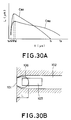
- Fig. 30A shows a curve of rearward displacement of each meniscus.
- a quantity of rearward displacement L ( ⁇ m) of a meniscus shown on an ordinate in Fig. 30A represents a length L in a liquid path 102 on the ink ejection outlet 101 side as shown in Fig. 30B.
- the length L is equal to a distance as measured from an ink ejection outlet 101 to the rearmost end of an ink meniscus 106.
- a meniscus 106 is positioned in the vicinity of the ink ejection outlet 101, and it is then quickly displaced in the rearward direction. Thereafter, a quantity of rearward displacement of the meniscus 106 is maximized at a time t1', and subsequently, the meniscus 106 starts to gradually return to the original position by the function of the restoring power induced by the surface tension. Finally, refill is completed at the time t1.
- a quantity of rearward displacement of the meniscus 106 is maximized at the same time as the time t1' or at the time t2' slightly later than the time t1'.
- a maximum value of quantity of rearward displacement of the meniscus 106 is small, and a refill speed of the meniscus 106 is slow as represented by t2.
- any particular problems does not arise with the reduction of the refill speed of the ink jet head including number of ink ejection outlets 101.
- a recording signal is applied to the energy generating unit 103 at the frequency shorter the time between the time t0 and the time t2
- a next recording signal is applied to the energy generating element 103 while refill is not completed, e.g., a quantity of rearward displacement of the meniscus 106 is 30 ⁇ m or more, a quantity of ejected ink droplets is reduced, resulting in good recording failing to be achieved.
- an assignee common to the present invention proposed a ink jet head including a pressure-volume converting unit capable of reversibly converting the pressure associated with refill into variation of a volume as disclosed in an official gazette of Japanese Patent Application Laying-Open No. 308644/1989.
- the ink jet head includes means for staying gas bubbles in a liquid chamber.
- the ink jet head proposed by the assignee contributes to the elimination of the aforementioned problems.
- the ink jet head is constructed in such a manner as to include a pressure-volume converting unit in the liquid chamber or adjacent to the liquid chamber, new components and a new process are additionally required. This leads to the result that the ink jet head is produced at the correspondingly increased cost.
- buffer chambers 7, 7 having gas bubbles 72, 72 grown therein is disposed sidewards of the array of energy generating elements.
- liquid vibration can satisfactorily be absorbed in the buffer chamber 7.
- the ink jet head includes a large number of energy generating elements, e.g., several thousand energy generating elements, the liquid vibration can not always satisfactorily be absorbed in the buffer chamber 7.
- the buffer chamber 7 contains large size of gas bubble so as to assure a sufficient buffer effect, it is unavoidably designed with large dimensions.
- a size of the ink jet head is undesirably enlarged.
- Another problem is that when two base boards, i.e., a first base board and a second base board are connected to each other, it is difficult that the first base board is correctly positionally aligned with the second base board, causing the ink jet head to be produced on the basis of mass production with much difficulties.
- the assignee invented a method of producing a liquid jet head wherein an active energy ray setting material is used as a material for forming a liquid path therein, and filed an application for patent under Japanese Patent Application Laying-Open No. 154947/1986.
- An object of the present invention is to provide an ink jet head and an ink jet apparatus which assure that a capability of ink refilling can substantially be improved without any occurrence of a malfunction that ink is incorrectly ejected especially at the beginning time of a recording operation, and moreover, they can be produced at an inexpensive cost with high speed responsiveness and excellent ink ejection stability.
- Another object of the present invention is to provide a method of producing an ink jet head at an inexpensive cost on the basis of mass production wherein there does hardly arise a malfunction that ink is incorrectly ejected from the ink jet head after the ink ejection outlets are not used for a long time, and moreover, high speed recording can be achieved at a high driving frequency.
- an ink jet head including a plurality of ink liquid paths arranged in the side-by-side relationship, each of the ink liquid paths including an energy generating element for generating energy required for ink ejection, and a common liquid chamber arranged in substantially parallel with a direction of arrangement of the plurality of ink liquid paths for feeding ink to the ink liquid paths, so as to eject ink from a plurality of ink ejection outlets by driving the energy generating elements
- the ink jet head comprises; an air chamber extending along an arrangement of the plurality of ink liquid paths and communicated with the common liquid chamber via a communication section located at the substantially central part thereof, the air chamber containing gas therein for absorbing pressure fluctuation propagating in the ink received in the common liquid chamber.
- the air chamber may be divided into plural segments.
- the communication section may include a plurality of communication path walls.
- a volume of the common liquid chamber may be larger than that of the air chamber.
- a cross-sectional area of each of the ink liquid paths may be equal to or larger than that of each of a plurality of communication paths defining the communication section.
- a total of the sectional areas of the communication paths defining the communication section may be equal to twice or more of value obtained by converting a total quantity of ink simultaneously ejected from all the ink ejection outlets into an area.
- a total of the sectional areas of the communication paths defining the communication section may be equal to 1/10 or more of the total cross-sectional area of the ink flow paths.
- the ink ejection outlets may be arranged in the form of a full-line head having a width corresponding to a width of a recording medium.
- Each of the energy generating elements may be a heat generating resistor element.
- an ink jet apparatus for performing a recording operation by ejecting ink, composes; an ink jet head including a plurality of ink liquid paths arranged in the side-by-side relationship, each of the ink liquid paths including an energy generating element for generating energy required for ink ejection, and a common liquid chamber arranged in substantially parallel with a direction of arrangement of the plurality of ink liquid paths for feeding ink to the ink liquid paths, so as to eject ink from a plurality of ink ejection outlets by driving the energy generating elements
- the ink jet head comprising; an air chamber extending along an arrangement of the plurality of ink liquid paths and communicated with the common liquid chamber via a communication section located at the substantially central part thereof, the air chamber containing gas therein for absorbing pressure fluctuation propagating in the ink received in the common liquid chamber, or the ink jet head where the air chamber is divided into plural segments, and conveying means for conveying a recording medium.
- a method of producing an ink jet head including a plurality of ink ejecting outlets for ejection ink therefrom, a plurality of ink liquid paths communicated with the ink ejection outlets, a plurality of energy generating elements arranged corresponding to the ink liquid paths, a common liquid chamber for feeding ink to the ink liquid paths, and an air chamber communicated with the common liquid chamber via a communication section
- the method comprise the steps of; providing a first base board having the plurality of energy generating elements arranged thereon in the side-by-side relationship, forming on the first base board, a mold member for forming the plurality of ink liquid paths, the common liquid chamber for feeding ink to the ink liquid paths, and the communication section; disposing a filling member in such a manner as to cover the mold member therewith, disposing a second base board having a groove formed thereon to constitute the common liquid chamber and the air chamber, and removing the mold member.
- the filling member may be a photosensitive resin, further comprising the step of conducting exposure treatment for removing a part of the filling member corresponding to the groove on the second base board, and moreover, removing a part of the mold member corresponding to the groove after the step of disposing the second base board.
- a plurality of the communication sections may be formed using the mold member, and a plurality of the air chambers are formed by sealably closing each air chamber between adjacent communication sections.
- Fig. 1 is a perspective view of an ink jet recording head constructed according to a first embodiment of the present invention
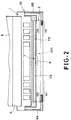
- Fig. 2 is a sectional view of the recording head shown in Fig. 1
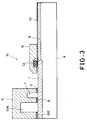
- Fig. 3 is an enlarged vertical sectional view of the recording head taken along a line B - B in Fig. 1.
- reference numeral 1 designates a first base board (heater board) made of a silicon substrate and having a plurality of energy generators (not shown), e.g., electrothermal converting elements (hereinafter referred to as ejection heaters) and number of wiring conductors each made of aluminum or the like for feeding electricity to the ejection heaters formed thereon by employing a film forming technique
- reference numeral 2 designates an ejection portion forming member (solid layer) having number of ink ejection outlets 101 for ejecting ink therefrom and number of liquid paths 102 communicated with the ejection outlets 101 formed therein, respectively
- reference numeral 3 designates a second base board for structuring a common liquid chamber 104 being communicated with the liquid paths 102 formed therein and having ink to be fed to the liquid paths 102 stored therein.
- the solid layer for structing the liquid paths 102 and being formed corresponding to the ejection heaters is laminated on the first base board 1, and a second base board 3 is laminated on the solid layer.
- the first base board 1 is positionally fixed on a base plate 4, and a flexible base board 5 for feeding electrical signals therethrough for the purpose of ejecting ink is exactly located relative to an electrical pad placed on the first base board 1.
- the base board 5 is firmly fixed to the base plate 4 in the compressed state by securing a flexible retainer 6 with tightening a bolt (not shown).
- a recording head 10 includes an air chamber (serving as a buffer chamber) in the second base board 3 located outside of a liquid chamber 104, and the liquid chamber 104 and the air chamber 7 are preformed in the form of two longitudinally extending parallel grooves by employing a cutting process or an injection-molding process before the second base board 3 is laminated on the solid layer 2.
- an air chamber serving as a buffer chamber
- the liquid chamber 104 and the air chamber 7 are preformed in the form of two longitudinally extending parallel grooves by employing a cutting process or an injection-molding process before the second base board 3 is laminated on the solid layer 2.
- a communication portion 8 is formed between the liquid chamber 104 and the air chamber 7 at the substantially central of the liquid paths 102 as seen in the longitudinal direction so as to establish communication therebetween.
- Ink feed tubes 11A and 11B (referring to Fig. 1) are connected to the opposite ends of the liquid chamber 104 via ink feed joints 9A and 9B, while the rear ends of the ink feed tubes 11A and 11B are connected to an ink tank (not shown).
- the opposite ends of the air chamber 7 are sealably closed with an adhesive or a similar material.
- ink is fed to the ink liquid chamber 104 from the ink tank via the ink feed tubes 11A and 11B. While the liquid chamber 104 and the liquid paths 102 are filled with ink, in response to a recording electrical signal fed to the ejection heaters 103, thermal energy is generated by the ejection heaters 103, causing the ink in the liquid paths 102 to be thermally affected, whereby ink droplets are ejected from number of ejection outlets 101 in conformity with the aforementioned pressure transmission mechanism to achieve a recording operation.
- a low intensity of squeezing power for squeezing ink toward the ink liquid path 104 from the respective liquid paths 102 in the A arrow-marked direction appears every time ink injection is completed.
- the foregoing pressure derived from the respective liquid paths 102 is absorbed in two regions 7A and 7B of the air chamber 7. Consequently, the generation of the power effective for returning ink from the ink liquid chamber 104 to the ink feed tubes 11A and 11B in the C arrow-marked direction is suppressed or prevented. Subsequently, as shown in Fig.
- the power effective for squeezing ink from the liquid paths 102 in the direction toward the liquid chamber 104 acts on the refilling power in the opposite direction.
- the power effective for squeezing ink from the liquid paths 102 in the direction toward the liquid chamber 104 is absorbed in both the regions 7A and 7B of the air chamber 7.
- this power effectively functions in such a manner as to compensate for the power for achieving ink refilling. Accordingly, ink refilling can smoothly be achieved for a short time. This makes it possible that the ink jet heat 10 can respond to the high driving frequency, and moreover, an excellent quality of image can be recorded at a high speed.
- the air chamber 7 is arranged in substantially parallel with the liquid chamber 104 common to a row of the energy generating elements and with the direction of the array of the ink liquid paths, gas sufficient to assuring a buffer effect can be reserved in the ink jet head 10 without any necessity for enlarging the ink jet head 10 itself. Furthermore, this arrangement enable the air chamber to be long and slender so that the power of air in the air chamber much effectively compensate for the power for achieving ink refilling.
- the communication portion 8 can formed at the same time when number of liquid paths 102 are formed through the solid layer 2. A method of forming the communication portion 8 and the liquid paths 102 will be described in detail later.
- a communication portion to be described hereinafter represents the whole communication forming region inclusive of a plurality of walls defined between adjacent communication paths (hereinafter referred to as communication path forming walls) in the case that a plurality of communication paths are concentratively formed in a single region.
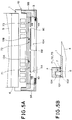
- the length of an air chamber as seen in the longitudinal direction of the head is substantially equally divided into plural air chamber segments, i.e., air chamber segments 71, 72 and 73.
- Reference numerals 12A and 12B designate partition walls for the air chamber segments 71, 72 and 73.
- the three air chambers 71, 72 and 73 are communicated with the a common ink chamber 104 via three communication paths 8A, 8B and 8C each located at the central part of each air chamber segment.
- the ink pressure transmitted from the liquid chamber 104 via the communication paths 8A, 8B and 8C during ink ejection can be absorbed in a plurality of air regions 71A, 71B, 72A, 72B, 73A and 73B (see Fig. 6) located in the vicinity of the communication paths 8A, 8B and 8C.
- the ink pressure transmitted in that way is conducted and then absorbed in a first air region section including the air regions 71A and 71B located on the opposite sides relative to the communication path 8A, a second air region section including the air regions 72A and 72B located on the opposite sides relative to the communication path 8B and a third air region including the air region 73A and 73B located on the opposite sides relative to the communication path 8C.
- the foregoing power is dispersively or distributively transmitted to air chambers 71, 72 and to 73 depending on the state of ink injection, and thereafter, absorbed in the air regions 71A and 71B of the air chamber 71, the air region 72A and 72C of the air chamber 72, and the air regions 73A and 73B of the air chamber 73.
- the power absorptively reserved in the air chambers 71, 72 and 73 is transmitted to the liquid chamber 104, and thereafter, it is applied to the respective liquid paths 102 in the B arrow-marked direction.
- a plurality of communication paths are formed between the central part of the air chamber and the common liquid chamber both of which extend in parallel with each other in the longitudinal direction of the second base board 3, so that plural sets of air regions are formed on the opposite sides of each communication path, and moreover, the communication paths are located at the positions remote from the ink supply routes.
- the structure of the ink jet head employed according to the second embodiment of the present invention is preferably employable especially in the case that number of ink ejection outlets and ink liquid paths are formed in the longitudinal direction.
- the structure of an ink jet head for preferably employable for effectively absorbing ink vibration and pressure wave induced at the time of ink ejecting will be described below.
- the ink jet head is exemplified by the structure as shown in Fig. 7.
- the structure of the ink jet head shown in Fig. 5 may be employed.
- Fig. 7 is a fragmentary sectional plan view of an ink jet head constructed according to a modified embodiment of the present invention, particularly showing that a single air chamber 7 is arranged in parallel with a common liquid chamber 104.
- reference numeral 8 designates a communication portion which is disposed at the substantially central part of the injection head 20 as seen in the longitudinal direction.
- the communication portion 8 includes a plurality of communication paths 8A arranged in the longitudinal direction.
- Reference numeral 8B designates a communication path forming wall which has two communication paths 8A, 8A located adjacent thereto.
- the common communication chamber 104 is designed to have a sufficiently large capacity compared with the air chamber 7.
- the ink jet head 20 includes a plurality of communication paths 8A for a single air chamber 7, to assure that the pressure generated toward the common liquid chamber 104 side at the time of ink ejecting through a number of ink paths 102 is quickly absorptively received, it is recommendable that the number of communication paths or the total sectional area of the latter is increased.
- a preset height of each ink ejection liquid path 102 is designated by h1
- a preset width of the same is designates by a
- a present height of each communication path 8A is designated by h2
- a preset width of the same is designated by b
- a preset width of each communication path forming wall 8B is designated by c.
- the sectional area of ink liquid path is represented by a ⁇ h1 and the sectional area of the communication path is represented by b ⁇ h2.
- Table 1 shows main comparison items of recording heads A, B and C used for the experiments.
- Table 1 name of head number of liquid paths width of liquid path ( ⁇ m) height of liquid path ( ⁇ m) pitch of liquid path number of communication paths ( ⁇ m) width of communication path ( ⁇ m) height of communication path ( ⁇ m) width of communication path forming wall ( ⁇ m) A 4736 38 24 400dpi 20 1000 24 1000 B 2048 65 48 203dpi (8pel) 16 1000 48 1000 C 1472 42 24 360dpi 14 500 24 500
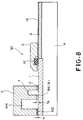
- the recording head 30 includes a communication portion 8 of which communication path 8A is dimensioned to have a height h2 higher than a height h1 of each liquid path 102.
- the recording head 30 can easily be fabricated by equalizing the height h2 of the communication path 8A to a height of the solid layer 2, i.e., a thickness of the same when the solid layer 2 is formed as will be described later.
- the width b of the communication path 8A is set to be equal to the width a of the liquid path 102, an effective refilling effect can be expected by satisfying the condition that a sectional area, that is, b ⁇ h2 of the communication path 8A is set to be larger than a sectional area a ⁇ h1 as represented in the above paragraph 1.
- each communication path 8A is designed to be suitable for an ink refilling operation.
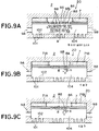
- a plurality of communication paths 8A formed at the substantially central part of a common liquid chamber 104 and an air chamber 7 are not arranged in the equally spaced relationship but as shown in the drawing, a width of each communication path forming wall 8B is widened from the central part toward the opposite sides.
- Reference characters C1 to C3 designate a width of each communication path forming wall 8B and reference character b designates a width of the communication path 8A.
- the width C3 of the outer communication path forming wall 8B is dimensioned to be larger than the width C2 of the intermediate communication path forming wall 8B, and the width C2 of the intermediate communication path forming wall 8B is dimensioned to be larger than the width C1 of the central communication path forming wall 8B.
- Fig. 9B and Fig. 9B illustrate the case that a sectional shape of each communication path forming wall 8B is modified in such a manner that the opposite end surfaces of each communication path forming wall 8B are configured to exhibit a U-shaped contour (Fig. 9B) or a V-shaped contour (Fig. 9C) in the symmetrical relationship relative to the central communication path 8A.
- the pressure generated in the respective liquid paths 102 is easily conducted to the opposite air regions 71A and 71B of the air chamber 7 via the U-shaped or V-shaped communication paths 8A, and thereafter, it is possibly uniformly returned to the liquid chamber 104 side.
- An advantage obtainable form the modified embodiment is that the strength of the communication portion 8 and associated portions can be increased by contouring the respective communication path forming wall 8B in that way.
- the liquid paths 102 and the communication paths 8A are constructed in such a manner as to establish the following inequality under a condition that the conditions shown in the second embodiment are satisfied.
- the inventors conducted a series of experiments at a driving frequency higher than that during an ordinary recording operation using experimental articles A1 to A4 of recording heads of which the number of communication paths is represented by m, of which width is represented by b and of which height h2 is represented by h2 as shown in Table 2. It was found from the results obtained from the evaluation on a quality of each recording operation that the experimental articles of recording heads A1 and A2 exhibited slight fluctuation in a quality of recording, the experimental articles of recording head A3 exhibits an excellent quality of recording, and the experimental article of recording head A4 exhibits a more excellent quality of recording operation.
- the inventors prepared experimental articles of recording heads A4, B and C as shown in Table 3 with reference to the results obtained from the results on a quality of each preceding recording operation and then conducted experiments again using the experimental articles of recording heads A4, B and C. On completion of the experimental recording operations, it was found that each of the experimental articles of recording heads A4, B and C exhibited an acceptable quality of recording operations.
- This embodiment is likewise concerned with a total sectional area of communication paths forming a communication portion and a total sectional area of liquid paths.
- a quantity of ink ejected every ejection is substituted for the number of communication paths and a sectional area of the latter are set in association with the quantity ejected ink.
- the number of communication paths 8A, a width of the same and a height of the same are set in such a manner as to settle the inequality (2).
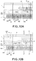
- Fig. 10 shows by way of fragmentary sectional view that number of ink liquid paths 102 and a mold member 20 for forming a communication portion 8 are disposed on a first base board 1 including number of energy generating portions 103 (e.g.., heat generating resistance elements or ejection heaters each serving to feed thermal energy to ink in the shown case) and circuits (not shown) for driving the ink ejecting energy generating portions 103.
- the mold member 20 is represented by a plurality of hatched lines in the drawing and contoured in the form of a convex portion.
- the white part of the first base board 1 in the drawing is an upper surface of the same, and a plurality of a concave portion 21 each serving as a column portion 8B of the communication port 8 are formed on the white part of the first base board 1 at a subsequent step.
- the first base board 1 is visually recognized below the mold member 20.
- the mold member 20 is formed in the location other than that corresponding to the ink liquid paths and the communication portions but the formation of the foregoing location is not always required. In practice, the mold member 20 is removed from the first base board 1 at a subsequent step.
- a material and means employed for the forming the mold member 20 will concretely be described below.
- a positive type dry film or a negative type dry film can be employed as a photosensitive dry film as explained in the paragraph (1).
- a preferably employable positive type dry film is such that it can be dissolved in a developing liquid by irradiating active energy rays thereto, while the negative dry film is prepared in the form of a photo-polymerizable type negative film which can be dissolved or removable peeled in a methylene chloride or a strong alkaline solution.
- the positive type dry film is exemplified by "OZATEC R225" (trade name, manufactured by Hoechst Japan Co. Ltd.), while the negative type dry film is exemplified by "OZATEC T series” (trade name, manufactured by Hoechst Japan Co., Ltd.), "PHOTOEC PHT series” (trade name, manufactured by Hitachi Kasei Kogyo Co., Ltd.) and "RISTON” (trade name, manufactured by Dupont de Nemours Co., Ltd.).
- a positively active resin compound e.g., a resin component containing naphkinon-diamide derivative and a novolac type phenol resin as main components
- negatively active resin compound e.g., a compound containing acrylorigomar having acrylester as an reactive group, thermoplastic high molecular compound and a sensitizer as main components
- a compound containing polyol, a polyethylene compound and a sensitizer are also employable.
- a photoresist layer employable for the solvent soluble polymer can typically be exemplified by a positive type photoresist containing a novolac type phenol resin and naphtokinon-diadid, a negative type liquid photoresist comprising a polyvinyl-sinarmate, a negative type photoresist containing a cyclic rubber and a bisadid, a negative type photosensitive dry film, a thermoset type ink, and an ultraviolet ray setting type ink.
- a material employable for forming the mold member 20 by employing a printing process is exemplified by a flat plate ink, a screen ink and a transferable type resin each of which is usable as a vaporization drying type, a thermoset type or an ultraviolet ray setting type.
- the positive type photosensitive material is most preferably employable from the viewpoint of forming a number of liquid paths 102, since it is superior to the negative type photosensitive material in respect of resolution, and moreover, it has an advantageous feature that a side wall surface of which relief pattern extends vertically and smoothly or a sectional shape having a tapered type or a reversely tapered type can easily be formed.
- the positive type photosensitive material has another advantageous feature that the relief pattern can removably be dissolved in a developing liquid and an organic solvent, it is preferably employable as a material for forming the mold member.
- the positive type photoresist including novolac type phenol resin and naphtokinon diadid as noted above is completely dissolved in a weak alkaline aqueous solution or alcohol, there does not arise a malfunction that each energy generating element (ejection heater) 103 is injured or damaged therewith, and moreover, a subsequent removing step can be achieved very quickly.
- a dry film-shaped positive type photosensitive material having a film thickness ranging from 10 ⁇ m to 100 ⁇ m can be noted as a most preferable material.
- a filling member 22 is laminated on the mold member 20 in such a manner as to cover the mold member 20 therewith, and the filling member 22 is filled in at least a concave portion of the mold member 20.
- any type of filling material is preferably employable, provided that the mold member 20 can be covered therewith.
- the filling material is a structural material employable for the liquid eject recording head 10 having number of liquid paths 102 and a liquid chamber 104 formed therein, it is desirable to select the filling material having excellent adhesiveness to the base board, a high mechanical strength, excellent dimensional stability and excellent corrosion resistance. Materials each hardenable when it is irradiated with active energy rays such as ultraviolet rays, visual light beam, X-rays, infrared rays, electron beams or the like while it is held liquid are suitably employable.
- epoxy resin acrylic resin, diglycol-dialkyl carbonate resin, unsaturated polyester resin, polyurethane resin, polyimido resin, melamine resin, phenol resin, and urea resin.
- epoxy resin capable of starting to effect cation polymerization in receipt of light beam acryl oligomars each having an acrylic ester group capable of starting to effect radical polymerization in receipt of light beam, light additive polymerizable type resin having polyol and polyethylene used therefor, and unsaturated cycloacethal resin are suitably employable as structural materials for an ink jet recording head.
- a method of ejecting a filling material from a plurality of nozzles arranged corresponding to the contour of a base board, a method of handling an applicator, a method of handling a curtain coater, a method of handling a roll coater, a method of handling a spray coater and a method of handling a spin coater can typically be noted as typical methods each for laminating the filling member 22 on the mold member 20.
- the mold member 22 is laminated with a liquid hardenable material, it of course is obvious that the liquid hardenable material is deaerated prior to lamination in order to avoid inclusion of gas bubbles in the hardened laminated material.
- Fig. 11A is an enlarged sectional view of the base board 1 filled with the filling material 22 taken along a line B - B' in Fig. 10
- Fig. 11B is an enlarged sectional view of the same taken along a line E - E' in Fig. 10.
- the respective mold members 20 are dissolved at a subsequent step so that they become cavities.
- the mold members 20 shown in Fig. 11A become ink liquid paths 102.
- the mold members 20 shown in Fig. 11B become communication paths 8 by way of which first grooves are communicated with second grooves for forming an air chamber 7.
- Mold member disposing portions 21 shown in Fig. 10 become columns 8B between the adjacent communication paths 8 at a step after they are filled by the filling member 22.
- a second base board 3 having two grooves formed therein is connectably placed on the first base board 1.
- Fig. 10B is a plan view which shows that the first base board and the second base board are laminated one above another.
- a significant fact to be taken into account is that a partition wall portion 13 between the two grooves are formed in such a manner as to cover the concave portion 21 therewith.
- the inner walls of the two groove on the first base board 1 have been coated with a shading layer made of a material having light shading capability against active energy rays effective for hardening the filled member 22 as will be described later.
- a method of dipping the first base board 1 in a shading layer solution so as to allow it to be coated therewith, and thereafter, wiping off predetermined fixed parts such as the concave portion 21 or the like and a method of adhering a masking tape to parts on the first base board 1 having no shading layer required thereon, and thereafter, dipping the first base board 1 so as to allow a necessary part of the latter to be coated therewith can be noted as a method to be advantageously employed for the purpose of forming a shading layer.
- a metallic film spattering method, an etching method or the like may be employed.
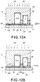
- Fig. 12A is an enlarged sectional view of the first base board 1 and the second base board 2 taken along a line C - C' in Fig. 10B
- Fig. 12B is an enlarged sectional view of the first base board 1 and the second base board 2 taken along a line D - D' in Fig. 10B.
- a shading layer 23 of the type as mentioned above is coated only on the inner wall of two grooves 24 and 25 of the second base board 3. In the case that active energy rays are reliably irradiated from above while maintaining the parallel relationship among them, it is acceptable that only a ceiling portion of each of the grooves 24 and 25 is coated with the shading layer 23.
- a portion which will later become an ink liquid path 102, a portion which will later become the ejection heater 103 and a portion which will later become the communication path 8 are included in the sectional plane extending along the line C - C'.
- a portion which will later become the ink path 102, a portion which will later become the ejection heater 103 and a portion which will later become the column 8B are included in the sectional plane extending along the line D - D'.
- the bottom wall of a front wall 27, the bottom wall of a partition wall 28 and the bottom wall of a rear wall 29 in the first base board 1 are adhesively connected to the second base board 3 via the hardened solid layer 2.
- UV rays can be utilized as active energy rays.
- active energy rays 26 which have permeated through the first base board 1
- ultraviolet rays and visual light beam are preferably employable.
- ultraviolet rays are most suitably employable as active energy rays from the viewpoint of a polymerization speed.
- any type of conventional light source can be utilized, provided that it is practically used for the purpose of producing a printing plate, handling a printed circuit or hardening a photosetting type paint.
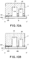
- the mold member 20 and an unhardened part of the filled member 22 are removed from the laminated structure so that the state of the laminated structure shown in Figs. 12A and 12B is shifted to that shown in Figs. 13A and 13B so as to form the ink liquid path 102, the communication path 8 and the column 8B.
- a process of dipping the laminated structure in a liquid capable of dissolving, expansibly swelling or peelably removing them therefrom Halogen-containing hydrocarbon, ketone, ester, aromatic hydrocarbon, ether, alcohol, N-methylpyroridon, dimethyl formaldehyde, phenol, water, acid-containing water or alkali-containing water can be noted as means for removing the mold member 20 and the filled member 22.
- a surface active agent may be added to each of the aforementioned liquids as desired.
- ultraviolet rays are additionally irradiated to the mold member to facilitate removable of the latter.
- other materials rather than the positive type dry film it is preferable that they are heated to the temperature range of 40 to 60 °C.
- the mold member 20 and the unhardened part of the filled member 22 are dipped and subjected to chemical treatment, they are dissolubly removed from the ink ejection outlet 101, the ink feed port 30, the communication path 8 and the two grooves 24 and 25.
- a shading layer dissolving agent is additionally mixed with the foregoing dissolving/dipping liquid, resulting in the number of steps being reduced. It of course is obvious that the shading layer may be removed at a different step.
- ink feed tube connecting members 9A and 9B are adhesively secured to the opposite ends of the two grooves, whereby an ink jet recording head is completed.
- first groove 24, i.e., one of the two grooves is communicated with the ink feed tubes 11A and 11B and the second groove 25, i.e., the other one of the two grooves is sealably closed with a part of each of the connecting members 9A and 9B
- the contour of each of the connecting members 9A and 9B is preliminarily designed so that the air chamber 7 is formed.
- the second groove 25 sealably closed with the connecting members 9A and 9B is communicated with the first groove 24 serving as a liquid chamber 104 only via the communication portion 8. Accordingly, when ink is introduced into the liquid chamber 104, the other region rather than the communication portion 8 aligned with the column 8B serves as an air reservoir. At this time, since the communication portion 8 serves as a kind of ink reservoir, this makes it possible to prepare for simultaneously eject ink from number of ink ejection outlets 101 at a high speed.
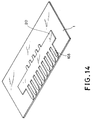
- a mold member 20 is formed on a first base board 1 having a plurality of ejection heaters 103, a heater driving circuit (not shown) and others formed therein in the same manner as the preceding embodiment.
- the mold member 20 is formed in the region positionally corresponding to a common liquid chamber 104, a liquid path 102 and a communication path 8A of a communication portion 8 as shown in Fig. 7, and a manner of forming these components and materials employed for forming them are same as those in the preceding embodiment.
- a column 8B is built by forming the concave portion on the mold member 20.
- a comb-shaped mold member is substituted for the concave portions.
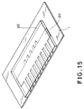
- a filled member layer 22 is formed on the mold member 20 in such a manner as to cover the mold member 20 therewith as shown in Fig. 15 using an active energy ray setting material such as an epoxy resin, an acrylic resin or the like.
- an active energy ray setting material such as an epoxy resin, an acrylic resin or the like.
- a second base board 3 is laminated on the filled member layer 22 as shown in Fig. 16.
- a common liquid chamber 104 and an air chamber 7 are preliminarily formed in the second base board 3.
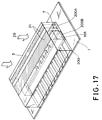
- photo-masks 21 are adhesively placed on the second base board 3 as shown in Fig. 17 in the regions located directly above the common liquid chamber 104 and the air chamber 7 as shown in Fig. 17, and thereafter, active energy rays 26 are irradiated toward the photo-masks 21 in the arrow-marked direction from above.
- a halogen-containing hydrocarbon is introduced into the second base board 3 so that the dissolved part of the second base board 3 is discharged from the common liquid chamber 104 and the air chamber 7, whereby the common liquid chamber 104, the air chamber 7, the liquid paths 102 and the ink ejection outlets 101 can simultaneously be formed together with the communication portion 8.
- the active energy rays 22 permeate through the filled member layer 22, causing the latter to be hardened.
- the bottom surface of a liquid path forming portion in the first base board 1, the bottom wall of a wall between the common liquid chamber 104 and the air chamber 7 and the bottom surface of a rear wall are adhesively connected to the second base board 3 via the hardened solid layer 2 (serving as a flow path forming member).
- the same power source for irradiating the active energy ray 22 as that employed in the preceding embodiment can likewise be used as a power source for the same purpose.
- a plurality of communication paths 8A are distributively arranged in the longitudinal direction of the air chamber 7 as shown in Fig. 19, when the common liquid chamber 104 is initially filled with ink as represented by arrow-marked directions, a certain amount of ink invades in the air chamber 7. This leads to the result that the air chamber 7 fails to exhibit a function as a buffer chamber. For this reason, it is necessary that a part of or some part of the air chamber 7 is designed in the form of a dead lane. To this end, in the case of an ink jet head as shown in Fig. 5, the air chamber 7 is divided into several sections using two partition members 12A so that communication paths 8A, 8B and 8C are formed at the substantially central parts of air chamber segments 7A, 7B and 7C.
- a slit 31 is formed at the substantially central part of a second base plate 3 having a first groove 24 and a second groove 25 formed therein. It should be careful that the slit 31 does not extend in excess of a partition wall 28 to reach the first groove 24.
- a slitting operation is performed by actuating a rotary grinding wheel or operating a cutting machine capable of accurately machining a material with the aid of a rotary grinding wheel or a similar tool.
- a mold member 20 having a first communication path forming portion 33 and a second communication path forming portion 34 formed thereon is placed on a solid layer 2, and three holes 21 are formed at both the communication path forming portions 33 and 34 in which columns 8B for a communication path 8 are later formed.
- the communication path forming sections 33 and 34 are filled with a photosensitive filling agent (not shown).
- a first base board 1 and a second base board 3 are adhesively connected to each other by employing the aforementioned process, and unnecessary parts are then dissolubly removed from the laminated structure.
- a partition wall plate 30 is inserted into the slit 31 and then adhesively secured to the latter.
- ink feed pipe connecting members 9A and 9B are adhesively connected to the opposite ends of the second base board 2 by employing the aforementioned process, whereby two air chambers can be formed with a partition wall interposed therebetween.
- an ink jet head including two ink storage and four air storage can be constructed.
- each air chamber is communicated with the liquid chamber 104 via the corresponding communication path.
- the present invention should not be limited only to a single partition wall 30. Alternatively, two or more partition walls 30 may be used so as to form air chambers more than the aforementioned case. It of course is obvious that the number of communication path forming portions varies correspondingly.
- Figs. 21A and 21B are views of an ink jet head which shows that two sealing agent filling holes 14 each serving to form a partition member 11 are preliminarily formed on a second base board 3 from above, and thereafter, a sealing agent 23 is injected through each filling hole 24 to form the partition wall 11 by solidifying the sealing agent 23.
- each filling hole can be formed on the second base board 3 by rotating a drill, irradiating a laser light beam or a supersonic jet toward the filling hole or employing a blasting process.
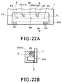
- FIGs. 22A and 22B are views of an ink jet head which show that two sealing agent filling holes 25 are formed in a second base board 3 from the rear side, and thereafter, a sealing agent 23 is injected through each filling hole 25 to form a partition member with the solidified sealing agent 23.
- Fig. 23 is a fragmentary plan view of an ink jet head which shows the state that a second base board 3 is laminated on a first base board 1 via a solid layer 2 (see Fig. 18) wherein e.g., two elastic materials 27 are squeezed from the opposite open ends of an air chamber 7 in the arrow-marked direction to reach the position where two partition members 11 are formed with the elastic materials 27.
- squeezing holes formed on the upper surface of the second base board 3 may be substituted for the opposite open ends of the air chamber 7.
- the present invention should not be limited only three air chambers defined according to the first embodiment of the present invention.
- the present invention should not be limited to a single communication path 8A to be formed corresponding to individual air chamber. It of course is possible to form a communication path similar to the communication paths 8A to 8C formed according to the first embodiment by additionally employing the technique according to the second embodiment of the present invention.
- the height of a communication path forming portion 20A is dimensioned to be equal to the thickness of a filled member layer 22 formed at a step as shown in Fig. 24B.
- the upper surface of the communication path forming portion 20A can positionally be coincident with the upper surface of the filled member layer 22.
- the ink jet head 30 as shown in Fig. 8 can be obtained by way of the aforementioned steps.
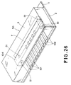
- Fig. 25 and Fig. 26 show by way of example an ink jet head 40 and an ink jet head 50 each including a second base board 3 of which structure is different from that constructed according to each of the aforementioned embodiments.
- the opposite ends of a common liquid chamber 104 and an air chamber 7 formed in the second base board 3 are not exposed to the outside in contrast with the aforementioned embodiments. Therefore, in this embodiment, there does not arise a necessity that opening portions on the opposite sides of the air chamber 7 are closed, and moreover, ink feed joints 9A and 9B are connected to opening portions on the opposite ends of the common liquid chamber 104.
- reference numeral 41 designates a hole.
- This hole 41 is formed in the vicinity of the opposite ends of the common liquid chamber 104 and the air chamber 7 at the upper portions of the both chamber so as to allow a solvent and a dissolved part of the solid layer and the mold member 20 to be discharged to the outside through the hole 41.
- reference numeral 51 designates a hole which is formed on the first base board 1 side for the same purpose as that of the hole 41. According to this embodiment, the ink jet heads 40 and 50 can be produced using the holes 41 and 51 by employing the aforementioned production method.
- Fig. 27 shows by way of schematic perspective view a so-called full line type recording head having a width corresponding to the recording width of a recording medium such as a paper or the like and a recording apparatus having a recording head of the foregoing type mounted thereon wherein among a plurality of recording heads to each of which the present invention is applicable, most remarkable advantages can be expected with the foregoing recording head.
- reference numeral 61 designates a full line recording head.
- ink is ejected from the recording head 61 toward a recording medium 80 such as a paper or the like so as to perform a recording operation. Since there does not arise a malfunction that a quality of recording is degraded with a long recording head like the full line recording head, an article having a high quality of image recorded thereon can be obtained with the recording head of the present invention.
- Fig. 28 shows by way of perspective view the structure of a recording apparatus having a small recording head mounted thereon.
- the recording apparatus includes a carriage HC on which an ink tank portion 70 and a recording head portion 60 are removably mounted.
- the recording apparatus includes a motor 81 serving as a power source for driving the carriage HC and rollers for conveying the recording medium 80, and a carriage shaft 85 for transmitting the power from the power source to the carriage HC.
- the apparatus further includes a signal supply means (not shown) for supplying a signal to the ink jet head, whereby ink is ejected from the ink jet head.
- the ink jet head of the present invention is employable for a recording apparatus as mentioned above.
- it is preferably employable not only for an ink jet apparatus including a signal receiving section for receiving an image signal from an unit located outside of the recording apparatus and the ink jet head of the present invention but also for an ink jet apparatus including a treatment mechanism for carrying out pretreatment and post-treatment for the purpose of ink fixing on a cloth and threads in addition to the foregoing ink jet head.
- the ink jet head of the present invention includes an air chamber extending in parallel with the direction of arrangement of a plurality of energy generating elements.
- the air chamber has a large volume enough to contain a large quantity of air therein for absorbing ink vibration and pressure fluctuation in the air. Consequently, the present invention can provide a so-called multi-nozzle type ink jet head and an ink jet apparatus which assure that good and quick refill can always be achieved by effectively utilizing the advantages obtainable from the air chamber and that excellent high-speed responsiveness and excellent ink ejection properties can be obtained without any appearance of the problems associated with ink refilling for a number of ink ejecting outlets.
- one of two grooves formed in a second base board is used as an ink feeding chamber and other one of the two grooves is used as an air chamber communicated with the ink feeding chamber via communication paths while a part of the air chamber located adjacent to the communication paths is used as an ink reservoir.
- the communication portion is constructed according to each of the aforementioned embodiments, ink vibration and pressure wave propagating in the ink can effectively be absorbed. Also in the case that recording is effected at a high speed, a high quality of recording can be assured.
- An ink jet head comprises a plurality of ink liquid paths (102) in which energy generating elements are formed, a common liquid chamber (104) communicated with the plurality of ink liquid paths (102), and an air chamber (7) which is communicated with the common liquid chamber (104) via a communication section (8) formed at substantially a central portion of the air chamber (7) and which is formed along the longitudinal direction of the common liquid chamber (104).
- This arrangement of the ink jet head enables air in the air chamber (7) to act on refilling behavior of ink in each of the ink liquid paths (102) so that refilling in each of the ink liquid paths (102) is not delayed.
Landscapes
- Engineering & Computer Science (AREA)
- Manufacturing & Machinery (AREA)
- Particle Formation And Scattering Control In Inkjet Printers (AREA)
Applications Claiming Priority (6)
| Application Number | Priority Date | Filing Date | Title |
|---|---|---|---|
| JP28146192 | 1992-10-20 | ||
| JP28146192 | 1992-10-20 | ||
| JP281461/92 | 1992-10-20 | ||
| JP89973/93 | 1993-04-16 | ||
| JP8997393 | 1993-04-16 | ||
| JP8997393 | 1993-04-16 |
Publications (3)
| Publication Number | Publication Date |
|---|---|
| EP0594110A2 true EP0594110A2 (de) | 1994-04-27 |
| EP0594110A3 EP0594110A3 (en) | 1995-10-25 |
| EP0594110B1 EP0594110B1 (de) | 2000-02-02 |
Family
ID=26431353
Family Applications (1)
| Application Number | Title | Priority Date | Filing Date |
|---|---|---|---|
| EP93116807A Expired - Lifetime EP0594110B1 (de) | 1992-10-20 | 1993-10-18 | Farbstrahldruckkopf, dessen Herstellungsverfahren und zugehöriges Farbstrahlgerät |
Country Status (3)
| Country | Link |
|---|---|
| US (1) | US5682190A (de) |
| EP (1) | EP0594110B1 (de) |
| DE (1) | DE69327762T2 (de) |
Cited By (6)
| Publication number | Priority date | Publication date | Assignee | Title |
|---|---|---|---|---|
| EP0684134A3 (de) * | 1994-05-27 | 1997-01-29 | Canon Kk | Tintenstrahlkopf, Tintenstrahlgerät und Verfahren zur Füllen einer Puffenkammer mit Blasen. |
| EP0786347A3 (de) * | 1995-12-26 | 1997-09-10 | Canon Kk | |
| EP0768180A3 (de) * | 1995-10-16 | 1997-10-01 | Canon Kk | Aufzeichnungskopf, Kopfkassette und Aufzeichnungsvorrichtung |
| EP1078760A3 (de) * | 1999-08-24 | 2001-05-16 | Canon Kabushiki Kaisha | Druckkopf und Tintenstrahldruckvorrichtung |
| EP2471657A1 (de) * | 2010-12-30 | 2012-07-04 | Tonejet Limited | Tintenverteiler für einen Tintenstrahldruckkopf |
| EP3536508A1 (de) * | 2018-03-06 | 2019-09-11 | Ricoh Company, Ltd. | Druckkopf |
Families Citing this family (43)
| Publication number | Priority date | Publication date | Assignee | Title |
|---|---|---|---|---|
| JP3459703B2 (ja) * | 1995-06-20 | 2003-10-27 | キヤノン株式会社 | インクジェットヘッドの製造方法、およびインクジェットヘッド |
| US6137510A (en) * | 1996-11-15 | 2000-10-24 | Canon Kabushiki Kaisha | Ink jet head |
| JP3768645B2 (ja) | 1997-06-18 | 2006-04-19 | キヤノン株式会社 | インクジェット記録ヘッド |
| JPH1178030A (ja) * | 1997-09-10 | 1999-03-23 | Brother Ind Ltd | インクジェットヘッドの製造方法 |
| JPH1199649A (ja) | 1997-09-30 | 1999-04-13 | Canon Inc | インクジェットヘッド、その製造方法、及びインクジェット装置 |
| US6523928B2 (en) | 1998-09-30 | 2003-02-25 | Xerox Corporation | Method of treating a substrate employing a ballistic aerosol marking apparatus |
| US6291088B1 (en) | 1998-09-30 | 2001-09-18 | Xerox Corporation | Inorganic overcoat for particulate transport electrode grid |
| US6290342B1 (en) | 1998-09-30 | 2001-09-18 | Xerox Corporation | Particulate marking material transport apparatus utilizing traveling electrostatic waves |
| US6454384B1 (en) | 1998-09-30 | 2002-09-24 | Xerox Corporation | Method for marking with a liquid material using a ballistic aerosol marking apparatus |
| US6265050B1 (en) | 1998-09-30 | 2001-07-24 | Xerox Corporation | Organic overcoat for electrode grid |
| US6416156B1 (en) | 1998-09-30 | 2002-07-09 | Xerox Corporation | Kinetic fusing of a marking material |
| US6751865B1 (en) | 1998-09-30 | 2004-06-22 | Xerox Corporation | Method of making a print head for use in a ballistic aerosol marking apparatus |
| US6340216B1 (en) * | 1998-09-30 | 2002-01-22 | Xerox Corporation | Ballistic aerosol marking apparatus for treating a substrate |
| US6467862B1 (en) | 1998-09-30 | 2002-10-22 | Xerox Corporation | Cartridge for use in a ballistic aerosol marking apparatus |
| US6511149B1 (en) | 1998-09-30 | 2003-01-28 | Xerox Corporation | Ballistic aerosol marking apparatus for marking a substrate |
| US6328409B1 (en) | 1998-09-30 | 2001-12-11 | Xerox Corporation | Ballistic aerosol making apparatus for marking with a liquid material |
| US6416157B1 (en) | 1998-09-30 | 2002-07-09 | Xerox Corporation | Method of marking a substrate employing a ballistic aerosol marking apparatus |
| DE19941871A1 (de) * | 1999-09-02 | 2001-04-19 | Hahn Schickard Ges | Vorrichtung und Verfahren zum Aufbringen einer Mehrzahl von Mikrotröpfchen auf ein Substrat |
| US6328436B1 (en) | 1999-09-30 | 2001-12-11 | Xerox Corporation | Electro-static particulate source, circulation, and valving system for ballistic aerosol marking |
| US6293659B1 (en) | 1999-09-30 | 2001-09-25 | Xerox Corporation | Particulate source, circulation, and valving system for ballistic aerosol marking |
| US6583069B1 (en) | 1999-12-13 | 2003-06-24 | Chartered Semiconductor Manufacturing Co., Ltd. | Method of silicon oxide and silicon glass films deposition |
| JP2001171119A (ja) * | 1999-12-22 | 2001-06-26 | Canon Inc | 液体吐出記録ヘッド |
| US6705691B2 (en) | 2000-01-14 | 2004-03-16 | Canon Kabushiki Kaisha | Ink-jet printing method and ink-jet printer |
| JP2002166553A (ja) * | 2000-11-30 | 2002-06-11 | Canon Inc | 液体吐出ヘッドおよび液体吐出ヘッドの製造方法 |
| CA2371027C (en) | 2001-02-09 | 2006-03-28 | Canon Kabushiki Kaisha | Pressure adjustment chamber, ink-jet recording head having the same, and ink-jet recording device using the same |
| US6997533B2 (en) * | 2001-04-02 | 2006-02-14 | Canon Kabushiki Kaisha | Printing head, image printing apparatus, and control method employing block driving of printing elements |
| US6715865B2 (en) | 2001-07-09 | 2004-04-06 | Canon Kabushiki Kaisha | Liquid jet recording head packing method, liquid jet recording head and liquid jet recording apparatus |
| JP3927854B2 (ja) | 2002-04-23 | 2007-06-13 | キヤノン株式会社 | インクジェット記録ヘッド |
| JP3768973B2 (ja) * | 2002-05-17 | 2006-04-19 | キヤノン株式会社 | インクジェット記録ヘッドおよびインクジェット記録ヘッドの製造方法 |
| US6969160B2 (en) * | 2003-07-28 | 2005-11-29 | Xerox Corporation | Ballistic aerosol marking apparatus |
| US7438403B2 (en) * | 2004-07-20 | 2008-10-21 | Brother Kogyo Kabushiki Kaisha | Inkjet printhead with compensating member |
| US7604327B2 (en) * | 2004-09-24 | 2009-10-20 | Brother Kogyo Kabushiki Kaisha | Liquid ejection apparatus and method for controlling liquid ejection apparatus |
| JP4724490B2 (ja) * | 2005-08-09 | 2011-07-13 | キヤノン株式会社 | 液体吐出ヘッド |
| JP2008143127A (ja) * | 2006-12-13 | 2008-06-26 | Canon Inc | 記録ヘッド及び記録装置 |
| US7984967B2 (en) * | 2007-04-13 | 2011-07-26 | Canon Kabushiki Kaisha | Ink jet head |
| JP2009051128A (ja) * | 2007-08-28 | 2009-03-12 | Canon Inc | 液体吐出ヘッド及び記録装置 |
| KR20140034000A (ko) * | 2012-09-11 | 2014-03-19 | 삼성전기주식회사 | 잉크젯 프린트 헤드 |
| US9385089B2 (en) * | 2013-01-30 | 2016-07-05 | Seagate Technology Llc | Alignment mark recovery with reduced topography |
| US9426886B2 (en) | 2013-01-30 | 2016-08-23 | Seagate Technology Llc | Electrical connection with reduced topography |
| US9343089B2 (en) | 2013-03-08 | 2016-05-17 | Seagate Technology Llc | Nanoimprint lithography for thin film heads |
| JP5728556B2 (ja) * | 2013-10-18 | 2015-06-03 | ユニ・チャーム株式会社 | 不織布の嵩回復装置 |
| US10668725B2 (en) | 2018-03-06 | 2020-06-02 | Ricoh Company, Ltd. | Supply manifold in a printhead |
| JP7331441B2 (ja) * | 2019-04-26 | 2023-08-23 | セイコーエプソン株式会社 | 液体噴射ヘッドおよび液体噴射装置 |
Family Cites Families (15)
| Publication number | Priority date | Publication date | Assignee | Title |
|---|---|---|---|---|
| US4403228A (en) * | 1981-03-19 | 1983-09-06 | Matsushita Electric Industrial Company, Limited | Ink jet printing head having a plurality of nozzles |
| US4611219A (en) * | 1981-12-29 | 1986-09-09 | Canon Kabushiki Kaisha | Liquid-jetting head |
| US4539569A (en) * | 1982-10-26 | 1985-09-03 | Canon Kabushiki Kaisha | Ink jet recording apparatus |
| JPS5998859A (ja) * | 1982-11-30 | 1984-06-07 | Seiko Epson Corp | インクジエツトヘツド |
| US4578687A (en) * | 1984-03-09 | 1986-03-25 | Hewlett Packard Company | Ink jet printhead having hydraulically separated orifices |
| JPH0645242B2 (ja) * | 1984-12-28 | 1994-06-15 | キヤノン株式会社 | 液体噴射記録ヘツドの製造方法 |
| EP0376922B1 (de) * | 1985-08-13 | 1993-07-28 | Matsushita Electric Industrial Co., Ltd. | Tintenstrahldrucker |
| JPS62179949A (ja) * | 1986-02-05 | 1987-08-07 | Canon Inc | インクジエツト記録ヘツド |
| EP0306341B1 (de) * | 1987-09-03 | 1993-01-07 | Matsushita Electric Industrial Co., Ltd. | Tintenstrahlaufzeichnungsgerät |
| JP2801196B2 (ja) * | 1987-11-20 | 1998-09-21 | キヤノン株式会社 | 液体噴射装置 |
| JP2718724B2 (ja) * | 1987-11-27 | 1998-02-25 | キヤノン株式会社 | インクジェット記録装置、該装置用キャップユニットおよびインクジェットヘッドの回復方法 |
| JPH01308644A (ja) * | 1988-06-07 | 1989-12-13 | Canon Inc | インクジェット記録ヘッド |
| JPH0234246U (de) * | 1988-08-29 | 1990-03-05 | ||
| US5220345A (en) * | 1989-03-31 | 1993-06-15 | Canon Kabushiki Kaisha | Ink jet recording apparatus |
| US5175567A (en) * | 1990-02-02 | 1992-12-29 | Canon Kabushiki Kaisha | Recording apparatus and recording head having an improved discharge post arrangement |
-
1993
- 1993-10-18 DE DE69327762T patent/DE69327762T2/de not_active Expired - Lifetime
- 1993-10-18 EP EP93116807A patent/EP0594110B1/de not_active Expired - Lifetime
- 1993-10-19 US US08/138,032 patent/US5682190A/en not_active Expired - Lifetime
Cited By (15)
| Publication number | Priority date | Publication date | Assignee | Title |
|---|---|---|---|---|
| EP0684134A3 (de) * | 1994-05-27 | 1997-01-29 | Canon Kk | Tintenstrahlkopf, Tintenstrahlgerät und Verfahren zur Füllen einer Puffenkammer mit Blasen. |
| US6109734A (en) * | 1994-05-27 | 2000-08-29 | Canon Kabushiki Kaisha | Ink-jet head, ink-jet apparatus and method of filling buffer chamber with bubbles |
| EP0768180A3 (de) * | 1995-10-16 | 1997-10-01 | Canon Kk | Aufzeichnungskopf, Kopfkassette und Aufzeichnungsvorrichtung |
| US6084611A (en) * | 1995-10-16 | 2000-07-04 | Canon Kabushiki Kaisha | Recording head, having pressure-bonding member for binding recording element substrate and driving element substrate, head cartridge and recording apparatus having same |
| US6055729A (en) * | 1995-12-24 | 2000-05-02 | Canon Kabushiki Kaisha | Method for manufacturing a liquid jet recording head |
| EP0786347A3 (de) * | 1995-12-26 | 1997-09-10 | Canon Kk | |
| EP1078760A3 (de) * | 1999-08-24 | 2001-05-16 | Canon Kabushiki Kaisha | Druckkopf und Tintenstrahldruckvorrichtung |
| US6557989B1 (en) | 1999-08-24 | 2003-05-06 | Canon Kabushiki Kaisha | Print head and ink jet printing apparatus |
| US6752492B2 (en) | 1999-08-24 | 2004-06-22 | Canon Kabushiki Kaisha | Print head and ink jet printing apparatus |
| EP2471657A1 (de) * | 2010-12-30 | 2012-07-04 | Tonejet Limited | Tintenverteiler für einen Tintenstrahldruckkopf |
| WO2012089549A1 (en) * | 2010-12-30 | 2012-07-05 | Tonejet Limited | Inlet manifold for an inkjet printhead |
| CN103328216A (zh) * | 2010-12-30 | 2013-09-25 | 唐杰有限公司 | 用于喷墨打印头的墨歧管 |
| US8845082B2 (en) | 2010-12-30 | 2014-09-30 | Tonejet Limited | Inlet manifold for an inkjet printhead |
| CN103328216B (zh) * | 2010-12-30 | 2016-04-13 | 唐杰有限公司 | 用于喷墨打印头的墨歧管 |
| EP3536508A1 (de) * | 2018-03-06 | 2019-09-11 | Ricoh Company, Ltd. | Druckkopf |
Also Published As
| Publication number | Publication date |
|---|---|
| EP0594110B1 (de) | 2000-02-02 |
| DE69327762T2 (de) | 2000-07-06 |
| DE69327762D1 (de) | 2000-03-09 |
| US5682190A (en) | 1997-10-28 |
| EP0594110A3 (en) | 1995-10-25 |
Similar Documents
| Publication | Publication Date | Title |
|---|---|---|
| EP0594110B1 (de) | Farbstrahldruckkopf, dessen Herstellungsverfahren und zugehöriges Farbstrahlgerät | |
| EP0564102B1 (de) | Grossbereich-Tintenstrahldruckkopf | |
| KR100508193B1 (ko) | 잉크젯프린터노즐판 | |
| US5408738A (en) | Method of making a nozzle member including ink flow channels | |
| EP0500068B1 (de) | Tintenstrahlaufzeichnungskopf, Tintenstrahlaufzeichnungsvorrichtung diesen verwendend und Verfahren zu seiner Herstellung | |
| US8128199B2 (en) | Ink jet print head, method for manufacturing ink jet print head, and printing apparatus | |
| US5332466A (en) | Liquid jet recording head manufacturing method | |
| JP3513199B2 (ja) | 液体噴射ヘッド、これを用いた液体噴射ヘッドカートリッジおよび記録装置、ならびに液体噴射ヘッドの製造方法 | |
| JP3305041B2 (ja) | インクジェットヘッド、その製造方法および前記インクジェットヘッドを備えたインクジェット装置 | |
| US5916452A (en) | Process for the production of an ink jet head | |
| US6508946B1 (en) | Method for manufacturing ink jet recording head, ink jet recording head, and ink jet recording apparatus | |
| JPH06344558A (ja) | インクジェットヘッド、該ヘッドの製造方法およびインクジェットヘッドを用いたインクジェット装置 | |
| US6626521B1 (en) | Liquid jet recording head, method for manufacturing same and liquid jet recording apparatus | |
| DE69612588T2 (de) | Tintenstrahldruckkopf, Verfahren zum Herstellen des Kopfes und Tintenstrahldrucker | |
| JPH054348A (ja) | インクジエツト記録ヘツドおよびその製造方法 | |
| JP3460421B2 (ja) | インクジェットヘッドの製造方法 | |
| JP3122195B2 (ja) | インクジェット記録ヘッド、その製造方法および前記インクジェット記録ヘッドを備えたインクジェット記録装置 | |
| JPH06191035A (ja) | インクジェット記録ヘッドおよびインクジェット記録装置 | |
| JP3198219B2 (ja) | インクジェット記録ヘッドおよびインクジェット記録装置 | |
| JP3025584B2 (ja) | インクジェット記録装置およびインクカセット | |
| JP3658153B2 (ja) | 液体噴射記録ヘッドの製造方法 | |
| JPH06312509A (ja) | インクジェット記録ヘッド、インクジェット記録ヘッドの製造方法および前記インクジェット記録ヘッドを備えたインクジェット記録装置 | |
| JPH09155892A (ja) | 液体噴射記録ヘッドの製造方法 | |
| JPH06312511A (ja) | 液体噴射記録ヘッドの製造方法、液体噴射記録ヘッドおよびインクジェット記録装置 | |
| JPH0584917A (ja) | 液体噴射記録ヘツドの製造方法 |
Legal Events
| Date | Code | Title | Description |
|---|---|---|---|
| PUAI | Public reference made under article 153(3) epc to a published international application that has entered the european phase |
Free format text: ORIGINAL CODE: 0009012 |
|
| AK | Designated contracting states |
Kind code of ref document: A2 Designated state(s): DE FR GB IT |
|
| PUAL | Search report despatched |
Free format text: ORIGINAL CODE: 0009013 |
|
| AK | Designated contracting states |
Kind code of ref document: A3 Designated state(s): DE FR GB IT |
|
| 17P | Request for examination filed |
Effective date: 19960305 |
|
| 17Q | First examination report despatched |
Effective date: 19961010 |
|
| GRAG | Despatch of communication of intention to grant |
Free format text: ORIGINAL CODE: EPIDOS AGRA |
|
| GRAG | Despatch of communication of intention to grant |
Free format text: ORIGINAL CODE: EPIDOS AGRA |
|
| GRAH | Despatch of communication of intention to grant a patent |
Free format text: ORIGINAL CODE: EPIDOS IGRA |
|
| GRAH | Despatch of communication of intention to grant a patent |
Free format text: ORIGINAL CODE: EPIDOS IGRA |
|
| GRAA | (expected) grant |
Free format text: ORIGINAL CODE: 0009210 |
|
| AK | Designated contracting states |
Kind code of ref document: B1 Designated state(s): DE FR GB IT |
|
| REF | Corresponds to: |
Ref document number: 69327762 Country of ref document: DE Date of ref document: 20000309 |
|
| ITF | It: translation for a ep patent filed | ||
| ET | Fr: translation filed | ||
| PLBE | No opposition filed within time limit |
Free format text: ORIGINAL CODE: 0009261 |
|
| STAA | Information on the status of an ep patent application or granted ep patent |
Free format text: STATUS: NO OPPOSITION FILED WITHIN TIME LIMIT |
|
| 26N | No opposition filed | ||
| REG | Reference to a national code |
Ref country code: GB Ref legal event code: IF02 |
|
| PGFP | Annual fee paid to national office [announced via postgrant information from national office to epo] |
Ref country code: IT Payment date: 20081020 Year of fee payment: 16 |
|
| PGFP | Annual fee paid to national office [announced via postgrant information from national office to epo] |
Ref country code: FR Payment date: 20081024 Year of fee payment: 16 |
|
| REG | Reference to a national code |
Ref country code: FR Ref legal event code: ST Effective date: 20100630 |
|
| PG25 | Lapsed in a contracting state [announced via postgrant information from national office to epo] |
Ref country code: FR Free format text: LAPSE BECAUSE OF NON-PAYMENT OF DUE FEES Effective date: 20091102 |
|
| PGFP | Annual fee paid to national office [announced via postgrant information from national office to epo] |
Ref country code: DE Payment date: 20101031 Year of fee payment: 18 |
|
| PG25 | Lapsed in a contracting state [announced via postgrant information from national office to epo] |
Ref country code: IT Free format text: LAPSE BECAUSE OF NON-PAYMENT OF DUE FEES Effective date: 20091018 |
|
| PGFP | Annual fee paid to national office [announced via postgrant information from national office to epo] |
Ref country code: GB Payment date: 20101019 Year of fee payment: 18 |
|
| GBPC | Gb: european patent ceased through non-payment of renewal fee |
Effective date: 20121018 |
|
| PG25 | Lapsed in a contracting state [announced via postgrant information from national office to epo] |
Ref country code: DE Free format text: LAPSE BECAUSE OF NON-PAYMENT OF DUE FEES Effective date: 20130501 Ref country code: GB Free format text: LAPSE BECAUSE OF NON-PAYMENT OF DUE FEES Effective date: 20121018 |
|
| REG | Reference to a national code |
Ref country code: DE Ref legal event code: R119 Ref document number: 69327762 Country of ref document: DE Effective date: 20130501 |