EP0594515B1 - Abnutzungswarnsensor für Kraftfahrzeugbremsbelag - Google Patents
Abnutzungswarnsensor für Kraftfahrzeugbremsbelag Download PDFInfo
- Publication number
- EP0594515B1 EP0594515B1 EP19930420403 EP93420403A EP0594515B1 EP 0594515 B1 EP0594515 B1 EP 0594515B1 EP 19930420403 EP19930420403 EP 19930420403 EP 93420403 A EP93420403 A EP 93420403A EP 0594515 B1 EP0594515 B1 EP 0594515B1
- Authority
- EP
- European Patent Office
- Prior art keywords
- piece
- seat
- lining
- cable
- zone
- Prior art date
- Legal status (The legal status is an assumption and is not a legal conclusion. Google has not performed a legal analysis and makes no representation as to the accuracy of the status listed.)
- Expired - Lifetime
Links
- 239000000463 material Substances 0.000 claims description 5
- 239000004696 Poly ether ether ketone Substances 0.000 claims description 4
- 125000000843 phenylene group Chemical group C1(=C(C=CC=C1)*)* 0.000 claims description 4
- 229920002530 polyetherether ketone Polymers 0.000 claims description 4
- 229920001021 polysulfide Polymers 0.000 claims description 4
- 229920003189 Nylon 4,6 Polymers 0.000 claims description 3
- 229920003023 plastic Polymers 0.000 claims description 3
- 239000004033 plastic Substances 0.000 claims description 3
- 239000004952 Polyamide Substances 0.000 claims description 2
- 229920002647 polyamide Polymers 0.000 claims description 2
- 230000011664 signaling Effects 0.000 claims description 2
- 230000002093 peripheral effect Effects 0.000 claims 1
- 239000004800 polyvinyl chloride Substances 0.000 description 8
- 229920000915 polyvinyl chloride Polymers 0.000 description 7
- 230000006835 compression Effects 0.000 description 5
- 238000007906 compression Methods 0.000 description 5
- 238000004519 manufacturing process Methods 0.000 description 4
- 238000009434 installation Methods 0.000 description 3
- 229920002302 Nylon 6,6 Polymers 0.000 description 2
- 230000007547 defect Effects 0.000 description 2
- 238000003780 insertion Methods 0.000 description 2
- 230000037431 insertion Effects 0.000 description 2
- 239000011810 insulating material Substances 0.000 description 2
- 239000005077 polysulfide Substances 0.000 description 2
- 150000008117 polysulfides Polymers 0.000 description 2
- -1 polytetrafluoroethylene Polymers 0.000 description 2
- 229920001343 polytetrafluoroethylene Polymers 0.000 description 2
- 239000004810 polytetrafluoroethylene Substances 0.000 description 2
- 239000004677 Nylon Substances 0.000 description 1
- 229920013632 Ryton Polymers 0.000 description 1
- 239000004736 Ryton® Substances 0.000 description 1
- 230000000712 assembly Effects 0.000 description 1
- 238000000429 assembly Methods 0.000 description 1
- 239000004020 conductor Substances 0.000 description 1
- 235000014510 cooky Nutrition 0.000 description 1
- 238000001514 detection method Methods 0.000 description 1
- 238000006073 displacement reaction Methods 0.000 description 1
- 239000000428 dust Substances 0.000 description 1
- 239000002783 friction material Substances 0.000 description 1
- 238000012423 maintenance Methods 0.000 description 1
- 239000002184 metal Substances 0.000 description 1
- 229920001778 nylon Polymers 0.000 description 1
- 229920001707 polybutylene terephthalate Polymers 0.000 description 1
Images
Classifications
-
- F—MECHANICAL ENGINEERING; LIGHTING; HEATING; WEAPONS; BLASTING
- F16—ENGINEERING ELEMENTS AND UNITS; GENERAL MEASURES FOR PRODUCING AND MAINTAINING EFFECTIVE FUNCTIONING OF MACHINES OR INSTALLATIONS; THERMAL INSULATION IN GENERAL
- F16D—COUPLINGS FOR TRANSMITTING ROTATION; CLUTCHES; BRAKES
- F16D66/00—Arrangements for monitoring working conditions, e.g. wear, temperature
- F16D66/02—Apparatus for indicating wear
- F16D66/021—Apparatus for indicating wear using electrical detection or indication means
- F16D66/022—Apparatus for indicating wear using electrical detection or indication means indicating that a lining is worn to minimum allowable thickness
- F16D66/023—Apparatus for indicating wear using electrical detection or indication means indicating that a lining is worn to minimum allowable thickness directly sensing the position of braking members
- F16D66/024—Sensors mounted on braking members adapted to contact the brake disc or drum, e.g. wire loops severed on contact
Definitions
- such witnesses are in the form of an electric cable, sheathed in an insulating material, and comprising at its end a tip also made of an insulating material, coming to be fixed at the level of the plate of which it is desired to detect wear.
- a contact is created materializing, in particular at the level of the dashboard of the vehicle, the wear of the plate.
- a witness is for example described in the document GB-A-2 115 893, which further provides that the end fitting for fixing the witness to the wafer has a terminal slot or groove, at the level of which the metal conductor is inserted beforehand folded into a U shape.
- This tip intended to be fixed at a seat provided for this purpose in the plate, is generally made of phenylene polysulphide (PPS), polyamide 6,6, polyamide 46, polyether etherketone (PEEK), or any other material having at least equivalent thermal and mechanical characteristics. It is overmolded on the end of the electric cable, itself sheathed in particular with polyvinyl chloride (PVC).
- PPS phenylene polysulphide
- PEEK polyether etherketone
- PVC polyvinyl chloride
- the object of the invention is to provide a wear indicator for brake pads overcoming these various drawbacks, and in particular capable of being fixed at the pad without requiring any additional part.
- This wear indicator comprises an electrical cable insulated in a plastic sheath, intended to convey an electrical signal signaling the wear of the wafer, and comprising at one of its ends an end piece surrounding the cable, and capable of being received in the seat of the plate provided for this purpose.
- This tip ends with a collar forming a stop to allow its maintenance. Said tip being intended to be force-fitted into the seat of the wafer.
- this end piece is molded onto the cable and has a longitudinal slot, extending radially from the central zone adjacent to the cable to the periphery, and this over the entire length of the end piece, except of the collar.
- this end piece can be force-fitted at the seat of the wafer which, in order to allow this insertion, has a through lumen, this slot allowing the end piece to be compressed on the PVC sheath , or PTFE (polytetrafluoroethylene) of the cable, and hence its cooperation with the internal periphery of the seat of the wafer. It is therefore no longer necessary to call on any additional part, in particular a lock washer.
- this profiled end piece has a cylindrical zone truncated over its entire length at the level of the cable, and extending at the level of the slot by a parallelepipedal zone, the median plane of which is constituted by the slot proper.
- the lateral faces of the parallelepipedal zone comprise ribs perpendicular to the cable, intended to increase the efficiency of the cooperation between said light of the seat of the wafer and said parallelepipedic zone, and consequently, to favor the fixing of said endpiece to this level.
- the diameter of the cylindrical zone and the width of the parallelepipedic zone of the endpiece are greater than the diameter of the orifice of the seat and than the width of the lumen of the seat of the insert, in order to ensure real compression and therefore cooperation of these two elements.
- the tip is made of a material chosen from the group comprising phenylene polysulfide, polyamide 6,6, polyamide 46, polyether etherketone, and any other material having at least equivalent thermal and mechanical characteristics.
- the end piece has a groove extending by a slot at the junction between the end piece and the flange, and corresponding substantially to the perimeter of the intersection of said end piece with the flange.
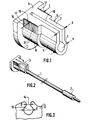
- Figure 1 is a schematic perspective representation of the wear indicator according to the invention.
- Figure 2 is a schematic perspective representation of the nozzle according to the invention.
- Figure 3 is a schematic sectional representation of a portion of the brake pad for receiving said tip.
- the indicator according to the invention basically comprises an electric cable (1) insulated by means of a plastic sheath, typically made of PVC (polyvinyl chloride). One end of this cable receives a male connector (2), intended to be plugged into the corresponding female connector of the dashboard or of a relay circuit intended to convey information, for example in the form of a light signal on the dashboard of the vehicle in question.
- a plastic sheath typically made of PVC (polyvinyl chloride).
- PVC polyvinyl chloride
- the other end of this cable (1) comprises an end piece (3), molded onto the cable (1) provided with its PVC sheath, and intended to allow its fixing at the seat (13) of a brake pad ( 12).
- such a brake pad intended to cooperate with the surface of a disc secured to the vehicle wheel, is made of a friction material, such as for example sold under the registered trademark Ferodo. Given this friction, and despite the material of which it is made, such a pad wears out over time and must be replaced regularly when this wear reaches a certain limit.
- the purpose of this wear indicator is to precisely materialize this wear visually, or even audibly to signal it to the user of the vehicle.
- the end piece (3) is typically made of phenylene polysulfide (RYTON - registered trademark), or even of polybutylene terephthalate, or even of polyamide 6.6 (NYLON - registered trademark). It is therefore molded onto the cable (1), and this automatically.
- This nozzle (3) has two parts, namely firstly a flange (4), intended to bear on the periphery of the seat (13) of the plate (12), and secondly, the nozzle itself said (5) intended to ensure the actual attachment of the witness to said wafer.
- the end piece (5) has, at the level of the area immediately adjacent to the collar (4), an additional thickness, both at the level of the parallelipipedal area (7) and of the cylindrical area (6), respectively (9) and (8), the length of which corresponds to the thickness of the seat (13).
- the external diameter D of the cylindrical zone (8) is slightly greater than the internal diameter d of the seat (13) of the plate (12).
- the thickness L of the parallelepiped part (9) is slightly greater than the width l of the opening (14) joining the seat (13) at the periphery of said plate (12).
- the width b of the parallelepiped part (7) corresponds to the width l of the lumen (14), and the external diameter a of the cylindrical part (6) corresponds to the internal diameter d of said seat (13).
- the lateral faces (16) and (17) of the thickened zone (9) of the parallelepipedal part are provided with parallel ribs (15) perpendicular to the cable (1) and parallel to the plane defined by the slot (10). These ribs cooperate with the light (14) of the seat, and oppose the displacement of the end piece out of said seat, after its installation.
- the end piece has at its junction with the flange (4) a groove (11) extending on the one hand, along the two lateral faces (16) and ( 17) of the parallelepiped part (9) and extends all around the cylindrical zone (8).
- this groove (11) corresponds to the perimeter of the intersection of the end piece (5) with the flange (4). It is intended to collect any chips and other dust likely to be created during the forceful clipping of the nozzle on the seat (13) of the wafer (12). In this way, we do not observe slight crossings of the tip, and therefore, the flange (4) is perfectly pressed against the plate (12), thus optimally fulfilling its role of wear indicator.
- the fixing of the wear indicator is optimized, favoring the good conditions for detecting wear.
Landscapes
- Engineering & Computer Science (AREA)
- General Engineering & Computer Science (AREA)
- Mechanical Engineering (AREA)
- Braking Arrangements (AREA)
Claims (7)
- Abnutzungsanzeiger für Kraftfahrzeugbremsbelag, mit einem elektrischen Kabel (1), das in einer Kunststoffhülle isoliert und dazu bestimmt ist, ein elektrisches Signal weiterzuleiten, das die Abnutzung des Belages (12) anzeigt, an dem er befestigt ist, und mit einem an einem seiner Enden befindlichen Ansatz (5), der in einem Sitz (13) aufnehmbar ist, der zu diesem Zweck im hinteren Teil des Belages (12) vorgesehen ist, wobei genannter Ansatz (5) in einem Kragen (4) endigt, der einen Anschlag bildet, der zur Anlage am Umfangsbereich des Sitzes (13) des Belages (12) vorgesehen ist, und wobei der genannte Ansatz dazu bestimmt ist, in den Sitz (13) des genannten Belages (12) eingepreßt zu werden, dadurch gekennzeichnet, daß der Ansatz (5) an das Kabel (1) angegossen ist und daß er einen längsverlaufenden Schlitz (11) aufweist, der sich von dem an das Kabel (1) angrenzenden Zentralbereich bis zum Umfang erstreckt, und zwar über die gesamte Länge des Ansatzes (5) mit Ausnahme des Kragens (4).
- Abnutzungsanzeiger nach Anspruch 1, dadurch gekennzeichnet, daß der Ansatz (5) einen zylindrischen Bereich (8) aufweist, der über seine gesamte Länge in Höhe des Kabels (1) abgestumpft ist, auf Höhe des Schlitzes (10) durch einen Bereich (9) in Form eines Parallelflach verlängert ist, dessen Mittelebene durch den Schlitz gebildet ist, wobei der genannte zylindrische Bereich (8) und der das Parallelflach bildende Bereich (9) dazu bestimmt sind, mit dem Sitz (13) bzw. einer Öffnung (14) zusammenzuwirken, die den genannten Sitz (13) mit der Peripherie des Belages (12) verbindet.
- Abnutzungsanzeiger nach Anspruch 2, dadurch gekennzeichnet, daß der zylindrische (8) und der ein Parallelflach bildenden Bereich (9) durch Bereiche gleicher Form verlängert sind, die jedoch jeweils kleinere Durchmesser und Dicken aufweisen.
- Abnutzungsanzeiger nach einem der Ansprüche 2 und 3, dadurch gekennzeichnet, daß die Seitenflächen (16, 17) des ein Parallelflach bildenden Bereiches (9) zum Kabel (1) senkrechte Rippen (16) besitzen, die zur Zusammenwirkung mit der Öffnung (14) des Sitzes (13) des Belages (12) bestimmt sind.
- Abnutzungsanzeiger nach einem der Ansprüche 1 bis 4, dadurch gekennzeichnet, daß der Ansatz (5) auf Höhe seines Bereiches, der mit dem Sitz (13) des Belages (12) zusammenwirkt, an dem er befestigt ist, ein Übermaß aufweist, wobei sich genanntes Übermaß über eine Strecke fortsetzt, die der Länge des Bereiches entspricht, in dem der genannte Ansatz (5) mit dem genannten Sitz zusammenwirkt.
- Abnutzungsanzeiger nach einem der Ansprüche 1 bis 5, dadurch gekennzeichnet, daß der Ansatz (5) aus einem Werkstoff gefertigt ist, der ausgewählt ist aus der Gruppe bestehend aus Phenylen-Polysulfid, Polyamid 6,6, Polyamid 46 und Polyether-Etherketon.
- Abnutzungsanzeiger nach einem der Ansprüche 1 bis 5, dadurch gekennzeichnet, daß der Ansatz (5) eine Einkehlung (11) aufweist, die auf der Ebene der Verbindung zwischen Ansatz (5) und Kragen (4) durch einen Schlitz verlängert ist und im wesentlichen dem Umfang der Schnittlinie zwischen dem genannten Ansatz und dem Kragen entspricht.
Applications Claiming Priority (2)
| Application Number | Priority Date | Filing Date | Title |
|---|---|---|---|
| FR9212820 | 1992-10-20 | ||
| FR9212820A FR2697065B1 (fr) | 1992-10-20 | 1992-10-20 | Témoin d'usure de plaquette de frein pour véhicule automobile. |
Publications (2)
| Publication Number | Publication Date |
|---|---|
| EP0594515A1 EP0594515A1 (de) | 1994-04-27 |
| EP0594515B1 true EP0594515B1 (de) | 1997-03-05 |
Family
ID=9434902
Family Applications (1)
| Application Number | Title | Priority Date | Filing Date |
|---|---|---|---|
| EP19930420403 Expired - Lifetime EP0594515B1 (de) | 1992-10-20 | 1993-10-14 | Abnutzungswarnsensor für Kraftfahrzeugbremsbelag |
Country Status (4)
| Country | Link |
|---|---|
| EP (1) | EP0594515B1 (de) |
| DE (1) | DE69308462T2 (de) |
| ES (1) | ES2099402T3 (de) |
| FR (1) | FR2697065B1 (de) |
Families Citing this family (3)
| Publication number | Priority date | Publication date | Assignee | Title |
|---|---|---|---|---|
| FR2722854B1 (fr) * | 1994-07-19 | 1996-09-13 | Cfca Division Surmoulage | Temoin d'usure de plaquette de frein pour vehicule automobile |
| FR2743126B1 (fr) * | 1995-12-27 | 1998-03-06 | Plastic Omnium Cie | Temoin d'usure de garniture de friction, notamment de plaquette de frein |
| DE602004018394D1 (de) * | 2004-04-30 | 2009-01-22 | Freni Brembo Spa | Fühler für verschleissanzeige für bremsbeläge |
Family Cites Families (2)
| Publication number | Priority date | Publication date | Assignee | Title |
|---|---|---|---|---|
| DE8206021U1 (de) * | 1982-03-04 | 1982-10-21 | Lucas Industries Ltd., Birmingham, West Midlands | Warnanzeigevorrichtung fuer belagverschleiss an bremsbacken |
| GB2231928B (en) * | 1989-05-26 | 1993-02-17 | Teves Gmbh Alfred | Spot-type disc brake |
-
1992
- 1992-10-20 FR FR9212820A patent/FR2697065B1/fr not_active Expired - Fee Related
-
1993
- 1993-10-14 DE DE1993608462 patent/DE69308462T2/de not_active Expired - Fee Related
- 1993-10-14 ES ES93420403T patent/ES2099402T3/es not_active Expired - Lifetime
- 1993-10-14 EP EP19930420403 patent/EP0594515B1/de not_active Expired - Lifetime
Also Published As
| Publication number | Publication date |
|---|---|
| DE69308462T2 (de) | 1997-06-12 |
| ES2099402T3 (es) | 1997-05-16 |
| FR2697065A1 (fr) | 1994-04-22 |
| FR2697065B1 (fr) | 1994-12-02 |
| EP0594515A1 (de) | 1994-04-27 |
| DE69308462D1 (de) | 1997-04-10 |
Similar Documents
| Publication | Publication Date | Title |
|---|---|---|
| FR3006119A1 (fr) | Appareillage electrique comportant un capteur de temperature loge dans un element de support | |
| EP2302276A1 (de) | Heizvorrichtung einer Fluidleitung | |
| FR2744962A1 (fr) | Allume-cigares a dispositif de protection, notamment pour vehicule automobile | |
| EP0594515B1 (de) | Abnutzungswarnsensor für Kraftfahrzeugbremsbelag | |
| EP1075055B1 (de) | Stromverteilereinrichtung mit mechanischer Steuerverriegelung des Steckers in der entsprechenden Steckdose | |
| FR2689322A1 (fr) | Dispositif à borne de prise de courant pour alternateur de véhicule automobile. | |
| EP0758961A1 (de) | Zigarettenanzünderkörper insbesondere für kraftfahrzeuge | |
| FR2742709A1 (fr) | Phare pour vehicule avec reflecteur | |
| EP0634586B1 (de) | Endstück für einen Reibbelagverschleisssensor, insbesondere für Bremsbeläge | |
| EP1410468A1 (de) | Ausziehgerät für einen elektrischen stecker relativ zu einer elektrischen steckdose | |
| EP0749376B1 (de) | Zigarettenanzünderkörper, insbesondere für kraftfahrzeuge | |
| EP0669481B1 (de) | System zum Erfassen des Verschleisses des Reibbelages einer Scheiben- oder Trommelbremse | |
| FR2722854A1 (fr) | Temoin d'usure de plaquette de frein pour vehicule automobile | |
| EP0172779B1 (de) | Mehrpoliger elektrischer Verbinder | |
| FR2620222A1 (fr) | Detecteur de proximite inductif et son procede de fabrication | |
| FR2724610A1 (fr) | Corps d'allumage pour allume-cigares, notamment pour vehicules automobiles | |
| FR2769410A1 (fr) | Bloc de contact pour socle de prise de courant | |
| EP0524113B1 (de) | Verbindungselement für einen elektrischen Kabelbaum mit einem in einer Isolierschicht eingebetteten elektrischen Leiter | |
| EP1251601A1 (de) | Elektromagnetische Abschirmungsvorrichtung für elektrische Verbinder | |
| WO2026092999A1 (fr) | Boîtier d'unité de commande comportant un bouclier à éléments poussoirs à bras élastiques parallèles au bord | |
| FR2754645A1 (fr) | Connecteur electrique basse tension | |
| FR2521341A1 (fr) | Contacteur manometrique pour vehicules automobiles et procede de realisation du support isolant des elements conducteurs pour celui-ci | |
| FR2652958A1 (fr) | Appareillage electrique a serre-cable exterieur imperdable. | |
| FR2689326A1 (fr) | Fiche de courant d'un accessoire, associée à un corps d'allumage d'un allume-cigares. | |
| FR3033671A1 (fr) | Contact electrique |
Legal Events
| Date | Code | Title | Description |
|---|---|---|---|
| PUAI | Public reference made under article 153(3) epc to a published international application that has entered the european phase |
Free format text: ORIGINAL CODE: 0009012 |
|
| AK | Designated contracting states |
Kind code of ref document: A1 Designated state(s): DE ES GB IT |
|
| 17P | Request for examination filed |
Effective date: 19940803 |
|
| 17Q | First examination report despatched |
Effective date: 19950419 |
|
| GRAG | Despatch of communication of intention to grant |
Free format text: ORIGINAL CODE: EPIDOS AGRA |
|
| GRAH | Despatch of communication of intention to grant a patent |
Free format text: ORIGINAL CODE: EPIDOS IGRA |
|
| GRAH | Despatch of communication of intention to grant a patent |
Free format text: ORIGINAL CODE: EPIDOS IGRA |
|
| GRAA | (expected) grant |
Free format text: ORIGINAL CODE: 0009210 |
|
| AK | Designated contracting states |
Kind code of ref document: B1 Designated state(s): DE ES GB IT |
|
| GBT | Gb: translation of ep patent filed (gb section 77(6)(a)/1977) |
Effective date: 19970305 |
|
| ITF | It: translation for a ep patent filed | ||
| REF | Corresponds to: |
Ref document number: 69308462 Country of ref document: DE Date of ref document: 19970410 |
|
| REG | Reference to a national code |
Ref country code: ES Ref legal event code: FG2A Ref document number: 2099402 Country of ref document: ES Kind code of ref document: T3 |
|
| PLBE | No opposition filed within time limit |
Free format text: ORIGINAL CODE: 0009261 |
|
| STAA | Information on the status of an ep patent application or granted ep patent |
Free format text: STATUS: NO OPPOSITION FILED WITHIN TIME LIMIT |
|
| 26N | No opposition filed | ||
| REG | Reference to a national code |
Ref country code: GB Ref legal event code: IF02 |
|
| PGFP | Annual fee paid to national office [announced via postgrant information from national office to epo] |
Ref country code: GB Payment date: 20040928 Year of fee payment: 12 |
|
| PGFP | Annual fee paid to national office [announced via postgrant information from national office to epo] |
Ref country code: DE Payment date: 20041007 Year of fee payment: 12 |
|
| PGFP | Annual fee paid to national office [announced via postgrant information from national office to epo] |
Ref country code: ES Payment date: 20041014 Year of fee payment: 12 |
|
| PG25 | Lapsed in a contracting state [announced via postgrant information from national office to epo] |
Ref country code: IT Free format text: LAPSE BECAUSE OF NON-PAYMENT OF DUE FEES;WARNING: LAPSES OF ITALIAN PATENTS WITH EFFECTIVE DATE BEFORE 2007 MAY HAVE OCCURRED AT ANY TIME BEFORE 2007. THE CORRECT EFFECTIVE DATE MAY BE DIFFERENT FROM THE ONE RECORDED. Effective date: 20051014 Ref country code: GB Free format text: LAPSE BECAUSE OF NON-PAYMENT OF DUE FEES Effective date: 20051014 |
|
| PG25 | Lapsed in a contracting state [announced via postgrant information from national office to epo] |
Ref country code: ES Free format text: LAPSE BECAUSE OF NON-PAYMENT OF DUE FEES Effective date: 20051015 |
|
| PG25 | Lapsed in a contracting state [announced via postgrant information from national office to epo] |
Ref country code: DE Free format text: LAPSE BECAUSE OF NON-PAYMENT OF DUE FEES Effective date: 20060503 |
|
| GBPC | Gb: european patent ceased through non-payment of renewal fee |
Effective date: 20051014 |
|
| REG | Reference to a national code |
Ref country code: ES Ref legal event code: FD2A Effective date: 20051015 |