EP0594522A1 - Servosystem für ein Plattengerät - Google Patents
Servosystem für ein Plattengerät Download PDFInfo
- Publication number
- EP0594522A1 EP0594522A1 EP93480139A EP93480139A EP0594522A1 EP 0594522 A1 EP0594522 A1 EP 0594522A1 EP 93480139 A EP93480139 A EP 93480139A EP 93480139 A EP93480139 A EP 93480139A EP 0594522 A1 EP0594522 A1 EP 0594522A1
- Authority
- EP
- European Patent Office
- Prior art keywords
- transducer
- actuator
- storage device
- data storage
- accelerometer
- Prior art date
- Legal status (The legal status is an assumption and is not a legal conclusion. Google has not performed a legal analysis and makes no representation as to the accuracy of the status listed.)
- Ceased
Links
- 230000001133 acceleration Effects 0.000 claims abstract description 34
- 239000000725 suspension Substances 0.000 claims abstract description 16
- 238000013500 data storage Methods 0.000 claims abstract description 15
- 238000004519 manufacturing process Methods 0.000 abstract description 2
- 238000012545 processing Methods 0.000 abstract description 2
- 238000010586 diagram Methods 0.000 description 7
- 238000013459 approach Methods 0.000 description 5
- 238000000034 method Methods 0.000 description 5
- 230000035939 shock Effects 0.000 description 5
- 230000000717 retained effect Effects 0.000 description 4
- 230000003111 delayed effect Effects 0.000 description 3
- 230000004069 differentiation Effects 0.000 description 3
- 230000010354 integration Effects 0.000 description 3
- 238000004364 calculation method Methods 0.000 description 2
- 230000008859 change Effects 0.000 description 2
- 238000013461 design Methods 0.000 description 2
- 229920001971 elastomer Polymers 0.000 description 2
- 239000000806 elastomer Substances 0.000 description 2
- 238000005516 engineering process Methods 0.000 description 2
- 101000606504 Drosophila melanogaster Tyrosine-protein kinase-like otk Proteins 0.000 description 1
- 230000003044 adaptive effect Effects 0.000 description 1
- 238000004458 analytical method Methods 0.000 description 1
- 230000000712 assembly Effects 0.000 description 1
- 238000000429 assembly Methods 0.000 description 1
- 238000004422 calculation algorithm Methods 0.000 description 1
- 239000003990 capacitor Substances 0.000 description 1
- 238000004891 communication Methods 0.000 description 1
- 238000004883 computer application Methods 0.000 description 1
- 230000000593 degrading effect Effects 0.000 description 1
- 238000009795 derivation Methods 0.000 description 1
- 239000012636 effector Substances 0.000 description 1
- 239000011159 matrix material Substances 0.000 description 1
- 239000002184 metal Substances 0.000 description 1
- 230000008520 organization Effects 0.000 description 1
- 239000002245 particle Substances 0.000 description 1
- 239000010453 quartz Substances 0.000 description 1
- 230000004044 response Effects 0.000 description 1
- 230000035945 sensitivity Effects 0.000 description 1
- 229910052710 silicon Inorganic materials 0.000 description 1
- 239000010703 silicon Substances 0.000 description 1
- VYPSYNLAJGMNEJ-UHFFFAOYSA-N silicon dioxide Inorganic materials O=[Si]=O VYPSYNLAJGMNEJ-UHFFFAOYSA-N 0.000 description 1
- 230000001360 synchronised effect Effects 0.000 description 1
- 230000002463 transducing effect Effects 0.000 description 1
- 230000009466 transformation Effects 0.000 description 1
Images


Classifications
-
- G—PHYSICS
- G11—INFORMATION STORAGE
- G11B—INFORMATION STORAGE BASED ON RELATIVE MOVEMENT BETWEEN RECORD CARRIER AND TRANSDUCER
- G11B21/00—Head arrangements not specific to the method of recording or reproducing
- G11B21/02—Driving or moving of heads
- G11B21/08—Track changing or selecting during transducing operation
-
- G—PHYSICS
- G11—INFORMATION STORAGE
- G11B—INFORMATION STORAGE BASED ON RELATIVE MOVEMENT BETWEEN RECORD CARRIER AND TRANSDUCER
- G11B5/00—Recording by magnetisation or demagnetisation of a record carrier; Reproducing by magnetic means; Record carriers therefor
- G11B5/48—Disposition or mounting of heads or head supports relative to record carriers ; arrangements of heads, e.g. for scanning the record carrier to increase the relative speed
- G11B5/54—Disposition or mounting of heads or head supports relative to record carriers ; arrangements of heads, e.g. for scanning the record carrier to increase the relative speed with provision for moving the head into or out of its operative position or across tracks
- G11B5/55—Track change, selection or acquisition by displacement of the head
- G11B5/5521—Track change, selection or acquisition by displacement of the head across disk tracks
- G11B5/5526—Control therefor; circuits, track configurations or relative disposition of servo-information transducers and servo-information tracks for control thereof
- G11B5/553—Details
- G11B5/5547—"Seek" control and circuits therefor
-
- G—PHYSICS
- G11—INFORMATION STORAGE
- G11B—INFORMATION STORAGE BASED ON RELATIVE MOVEMENT BETWEEN RECORD CARRIER AND TRANSDUCER
- G11B21/00—Head arrangements not specific to the method of recording or reproducing
- G11B21/02—Driving or moving of heads
- G11B21/10—Track finding or aligning by moving the head ; Provisions for maintaining alignment of the head relative to the track during transducing operation, i.e. track following
- G11B21/106—Track finding or aligning by moving the head ; Provisions for maintaining alignment of the head relative to the track during transducing operation, i.e. track following on disks
Definitions
- This invention pertains to data storage devices wherein information is stored on adjoining tracks and more particularly to an improved servo system for moving transducers from track to track or maintaining a transducer in alignment with a desired track in such a device.
- the servo system that positions the transducers with respect to a desired data track through the control of t he voice coil motor t hat carries t he transducers may take several forms.
- the most common techniques for determining head velocity and/or acceleration is to either differentiate position information or estimates the velocity as an internal state of the plant via a model based observer.
- the use of the differentiation technique requires the prediction of head future positions which is achieved in practice using numerical analysis techniques such as Euler second order. With an available head position signal, a numerical differentiation can be executed. This differentiation estimation is very noisy and unstable and induces many errors.
- the other approach for estimating this internal state consists of building a model based observer for generating estimates of the observable states. This last approach is more popular and reliable.
- Japanese patent JP 60-124073 shows the use of accelerometers mounted on the actuator arm in two planes to measure the impact power as the actuator armature strikes the inner or outer crash stops.
- US patent 3,836,835 includes one embodiment wherein an accelerometer is used in a system for controlling the operation of a synchronous planar motor with digital velocity feedback.
- the patent is directed to the use of an accelerometer on the motor that is traveling in the directions ofX and Ycoordinates without available position information.
- the application is a robot or assembly table, not a data storage device.
- the obtained acceleration is the acceleration of the moving assembly (i.e., head, actuator, end effector) with respect to the stationary part (the platen).
- a microaccelerometer is used to obtain the linear acceleration of a carried part (the transducer head) and not the rotational acceleration of the controlled voice coil motor.
- a direct feedback of actual acceleration is provided to the controller.
- This actual acceleration signal can also be supplied directly to the observer to improve estimates in a device that requires an observer for bias state estimate use in the controller.
- an observer can be eliminated.
- the dependency of the used acceleration signals on the model parameters and disturbances is eliminated resulting in a more robust overall control scheme.
- the velocity signals will be better computed with the actual integration of the acceleration.
- an accelerometer is also more effective in sensing and compensating for outside disturbances such as vibration or shock caused by jarring or dropping the device.
- the accelerometer can detect sudden disturbances that cause track misregistration and suspend the reading or writing of data more quickly than systems that sense and compensate only after the offtrack condition has occurred. Thus, when writing data, it is possible to intervene and suspend the write operation before adjoining data is destroyed.
- Fig. 1 shows an exploded view of a typical magnetic data storage disk drive including the head-disk assembly.
- Fig. 2 is an enlarged view of the head-suspension assembly incorporating a microaccelerometer.
- Fig. 3 is a block diagram of a prior art disk drive actuator motor control system.
- Fig. 4 is a block diagram of a disk drive actuator motor servo control system incorporating the present invention.
- Fig. 5 is a block diagram, similar to Fig. 4, wherein the observer has been retained.
- Fig. 6 is a lower level block diagram of Fig. 4 illustrating the control system of the present invention in greater detail.
- Fig. 1 shows the organization of a typical disk drive mounted on a frame 14.
- the disks 8 are amounted about a hub 6 which contains the spindle drive motor (not shown).
- the spindle shaft 9, which forms a part of the stator of the spindle drive motor, is secured at each end to the box frame 12 by bolts (one of which is shown).
- the actuator body 36 has a comb portion that presents a series of arms 37.
- the uppermost and lowermost arms 37 carry a single transducer 38 and resilient suspension 39 which respectively confront the upper and lower disk surfaces of the disk stack 8 while each intermediate arm extends between confronting disk surfaces and carries two transduc- er/suspension assemblies.
- the body 36 carries projections 41,42 which support the voice coil motor coil 44.
- Actuator shaft 40 is secured to box frame 12 by an upper bolt 45 and a similar lower bolt that is not visible.
- a pair of voice coil motor core elements 49 are mounted on box frame 12 by a series of bolts 47 in the form of members having an E shaped cross section which abut one another and which have permanent magnets 50 attached thereto.
- This core assembly provides an air gap 51 across which a magnetic field is maintained and in which the vertically extending stretches of the voice coil 44 are positioned.
- a cover 53 and gasket 54 are secured to the end of box frame 12 to cover and seal the end.
- a shock mount pin 54 is mounted on cover 53.
- the shank portion of pin 56 is surrounded by an elastomer ring 57 and received in a U-shaped recess (not visible) in the wall of frame 14 and retained therein by a clip 58.
- Box frame projection 60 includes a shank 61 which is surrounded by an elastomer ring 65 and received in U-shaped frame recess 62 where it is retained by clip64.
- a similar shock mount assembly, carried by box frame 12, is received in the U-shaped recess 63.
- the transducer coils and accelerometer are connected to the drive electronics by a flat cable 75 which extends from the actuator body 12 to a connector outside the head disk enclosure partly defined by the box frame 12.
- Fig. 2 is an enlarged view of the head-suspension assembly including suspension 39 and transducer head 38.
- Suspension 39 is formed of thin resilient metal and is mounted to the actuator arm 37 at a rearward position 28.
- the forward flexure portion 29 is rigidified by turning marginal portions to form flanges 30 while flexibility is provided by the intermediate flat portions 31.
- the distal end of the flexure portion 29 serves as a load beam which functions with the gimbal spring 32 to interconnect the transducer head 38 and the flexure 39 and provide for pitch and roll of the head 38 with respect to load beam portion 29.
- This mounting technique is shown and more fully described in US Patent 4,167,765. Wires 24 from the transducer coil pass through a snare tube 25 which extends along one side of flexure 39, to interconnect the transducer coil with the flat cable 75.
- a microaccelerometer is attached to the actuator either on one of the suspensions 39 in close proximity to the transducer carrying slider as illustrated by the dotted line position 33 or on the upper surface of one of the sliders as indicated by the positions 34 possibly by integrating the accelerometer with the slider during head manufacture.
- the accelerometer is used to measure horizontal acceleration, that is, acceleration in a direction parallel to the media surface.
- the preferred structure is to have the accelerometer integrated into the head assembly and vertically aligned above the transducing gap. When necessary to position the accelerometer with a linear offset from the transducer gap, a linear constant transformation is used to correct the sensed values.
- microaccelerometers have dimensions of about 100 microns in each dimension (length, width and height) and can be hybrid devices to provide accurate sensing of both lowfrequen- cy and high frequency acceleration.
- Piezoelectric (change in charge) sensing is used for measuring high frequency acceleration
- capacitive (change in capacitor value) sensing is used to measure lowfre- quency acceleration to afford a device with a wide frequency capability.
- the hybrid microaccelerometer can be fabricated using standard CMOS wafer processing.
- the PLANT is the electromechanical assembly of the drive actuator.
- the diagram of Fig.2 illustrates the typical current design servo system utilizing estimated velocity and bias signals. Based on the dynamical model of the voice coil motor and using the input/output/reference signals of the plant, the velocity and bias signals are observed (estimated). Further, the acceleration is assumed to be the delayed input (delayed control state) and used to generate the control signal. This assumption about the acceleration is not robust in the presence of model/parameter uncertainties. In addition, the same assumption becomes ill justified in the presence of external and internal disturbances in small form factor hard disk drives as they may be applied in portable computer applications.
- the estimator model accounts for the delay by using the previous control value as the state.
- the integral state variable is not even an observable state; therefore, the estimator gain element for this state must also be zero.
- the position variable is a known state that is measured during the current discrete-time sample and is used to generate the variables that are actually being estimated.
- the block diagram of Fig. 4 illustrates the use of the present invention in a disk drive environment.
- Direct feedback of actual acceleration is provided to the controller. This eliminates the dependency of the utilized acceleration on the model parameters and disturbances resulting in a more robust overall control scheme. It is advantageous to integrate the acceleration signal to generate the velocity instead of using the costly and questionable estimation of that signal. The observer block becomes unnecessary since most of today's applications do not use the uncontrollable bias state in the controller, especially when the velocity state is a direct integration of the actual acceleration signal.
- Fig. 5 illustrates the use of the invention while still using an observer in those applications wherein the uncontrollable estimated bias state is fed back by the control system design for perfect cancelation. However, in this environment, the actual measured acceleration is also fed back to the observer to eliminate the dependency on model parameters and disturbances.
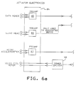
- the servo system block diagram of Fig. 6 shows the present invention in the environment of a disk drive having a dedicated servo surface.
- the actuator electronics 84 commonly called arm electronics, is usually associated with the flat cable (cable 75 of Fig. 1) that electrically connects the movable actuator assembly portion with the drive circuitry.
- Preamp circuits 85, 86, 87 are normally contained in a circuit module directly attached to the flat cable.
- the data heads and servo head are respectively connected to the preamp circuits 85 and 86 respectively with the output going to a demodulator 90 in the analog circuitry 89.
- the position information is retained in registers 93 of the digital circuitry 92.
- the output of the microaccelerometer is connected to preamp 87 with the output digitized by analog to digital converter91 and stored in registers in module 93.
- the processor 94 includes the control algorithm 95 which uses the demodulated position and acceleration values stored in the registers of module 93 to generate a voice coil motor (VCM) control signal using circuitry 96.
- VCM voice coil motor
- the VCM control signal is processed through circuit 97 and digital to analog converter 98 to enable power driver 99 to apply a current of the correct magnitude and sign to the actuator voice coil.
Landscapes
- Moving Of Head For Track Selection And Changing (AREA)
- Moving Of The Head To Find And Align With The Track (AREA)
Applications Claiming Priority (2)
| Application Number | Priority Date | Filing Date | Title |
|---|---|---|---|
| US96566092A | 1992-10-23 | 1992-10-23 | |
| US965660 | 1992-10-23 |
Publications (1)
| Publication Number | Publication Date |
|---|---|
| EP0594522A1 true EP0594522A1 (de) | 1994-04-27 |
Family
ID=25510295
Family Applications (1)
| Application Number | Title | Priority Date | Filing Date |
|---|---|---|---|
| EP93480139A Ceased EP0594522A1 (de) | 1992-10-23 | 1993-09-21 | Servosystem für ein Plattengerät |
Country Status (5)
| Country | Link |
|---|---|
| EP (1) | EP0594522A1 (de) |
| JP (1) | JP2599558B2 (de) |
| KR (1) | KR940010029A (de) |
| CN (1) | CN1035457C (de) |
| TW (1) | TW325557B (de) |
Cited By (3)
| Publication number | Priority date | Publication date | Assignee | Title |
|---|---|---|---|---|
| US6064540A (en) * | 1998-03-30 | 2000-05-16 | International Business Machines Corporation | Active control for stabilizing a servo-controlled actuator system |
| WO2001008138A1 (en) * | 1999-07-23 | 2001-02-01 | Seagate Technology Llc | Disturbance rejection for disc drives using adaptive accelerometer feedforward servo |
| US6771454B2 (en) | 2000-10-13 | 2004-08-03 | Seagate Technology Llc | Suspension sense capability for windage control |
Families Citing this family (4)
| Publication number | Priority date | Publication date | Assignee | Title |
|---|---|---|---|---|
| US5689384A (en) * | 1994-06-30 | 1997-11-18 | International Business Machines Corporation | Timing based servo system for magnetic tape systems |
| US6958871B2 (en) * | 2003-09-17 | 2005-10-25 | Hitachi Global Storage Technologies Netherlands B.V. | Head-disk interaction sensor integrated with suspension |
| US7312941B2 (en) * | 2003-09-17 | 2007-12-25 | Hitachi Global Storage Technologies Netherlands B.V. | Disk drive with head-disk interaction sensor integrated with suspension |
| JP4261468B2 (ja) * | 2004-11-18 | 2009-04-30 | Tdk株式会社 | 加速度センサ |
Citations (6)
| Publication number | Priority date | Publication date | Assignee | Title |
|---|---|---|---|---|
| JPS5737780A (en) * | 1980-08-15 | 1982-03-02 | Nec Corp | Positioning device of magnetic disk device |
| JPS59146486A (ja) * | 1983-02-09 | 1984-08-22 | Nec Corp | 磁気デイスク装置のヘツド位置決めサ−ボ機構 |
| EP0130836A2 (de) * | 1983-06-30 | 1985-01-09 | Unisys Corporation | Anordnung zur Positionierungsgenauigkeit eines Zugriffarmes |
| EP0263962A2 (de) * | 1986-10-14 | 1988-04-20 | Hewlett-Packard Company | System zur Positionierung und Spurnachfolgeregelung in einer Platteneinheit |
| EP0264535A2 (de) * | 1986-10-24 | 1988-04-27 | Hewlett-Packard Company | Ausgleichverfahren für Stoss- und Vibrationsstörung für einen Plattenantrieb |
| EP0306715A1 (de) * | 1987-08-11 | 1989-03-15 | Fujitsu Limited | Kontrolsystem für Magnetkopfpositionierer in einem magnetischen Plattenspieler mit mehreren Positionierern |
Family Cites Families (5)
| Publication number | Priority date | Publication date | Assignee | Title |
|---|---|---|---|---|
| GB1079450A (en) * | 1963-06-05 | 1967-08-16 | Unilever Ltd | Fatty products and their preparation |
| JPS60124073A (ja) * | 1983-12-07 | 1985-07-02 | Fujitsu Ltd | ヘッドクラッシュの加速評価方法 |
| JPS60136972A (ja) * | 1983-12-26 | 1985-07-20 | Hitachi Ltd | 磁気デイスク装置 |
| JPH02214074A (ja) * | 1989-02-14 | 1990-08-27 | Toshiba Corp | データ記録再生装置のヘッド位置決め制御装置 |
| JPH0376064A (ja) * | 1989-08-18 | 1991-04-02 | Tokico Ltd | 浮上式磁気ヘッドおよびこれを用いた磁気ディスク装置 |
-
1993
- 1993-08-26 TW TW082106930A patent/TW325557B/zh active
- 1993-08-30 JP JP5214608A patent/JP2599558B2/ja not_active Expired - Lifetime
- 1993-09-21 EP EP93480139A patent/EP0594522A1/de not_active Ceased
- 1993-09-23 KR KR1019930019377A patent/KR940010029A/ko not_active Ceased
- 1993-10-21 CN CN93119168A patent/CN1035457C/zh not_active Expired - Fee Related
Patent Citations (6)
| Publication number | Priority date | Publication date | Assignee | Title |
|---|---|---|---|---|
| JPS5737780A (en) * | 1980-08-15 | 1982-03-02 | Nec Corp | Positioning device of magnetic disk device |
| JPS59146486A (ja) * | 1983-02-09 | 1984-08-22 | Nec Corp | 磁気デイスク装置のヘツド位置決めサ−ボ機構 |
| EP0130836A2 (de) * | 1983-06-30 | 1985-01-09 | Unisys Corporation | Anordnung zur Positionierungsgenauigkeit eines Zugriffarmes |
| EP0263962A2 (de) * | 1986-10-14 | 1988-04-20 | Hewlett-Packard Company | System zur Positionierung und Spurnachfolgeregelung in einer Platteneinheit |
| EP0264535A2 (de) * | 1986-10-24 | 1988-04-27 | Hewlett-Packard Company | Ausgleichverfahren für Stoss- und Vibrationsstörung für einen Plattenantrieb |
| EP0306715A1 (de) * | 1987-08-11 | 1989-03-15 | Fujitsu Limited | Kontrolsystem für Magnetkopfpositionierer in einem magnetischen Plattenspieler mit mehreren Positionierern |
Non-Patent Citations (2)
| Title |
|---|
| PATENT ABSTRACTS OF JAPAN vol. 6, no. 108 (P - 123) 18 June 1982 (1982-06-18) * |
| PATENT ABSTRACTS OF JAPAN vol. 8, no. 282 (P - 323) 22 December 1984 (1984-12-22) * |
Cited By (6)
| Publication number | Priority date | Publication date | Assignee | Title |
|---|---|---|---|---|
| US6064540A (en) * | 1998-03-30 | 2000-05-16 | International Business Machines Corporation | Active control for stabilizing a servo-controlled actuator system |
| WO2001008138A1 (en) * | 1999-07-23 | 2001-02-01 | Seagate Technology Llc | Disturbance rejection for disc drives using adaptive accelerometer feedforward servo |
| GB2366906A (en) * | 1999-07-23 | 2002-03-20 | Seagate Technology Llc | Disturbance rejection for disc drives using adaptive accelerometer feedforward servo |
| US6580579B1 (en) | 1999-07-23 | 2003-06-17 | Seagate Technology Llc | Disturbance rejection for disc drives using adaptive accelerometer feedforward servo |
| GB2366906B (en) * | 1999-07-23 | 2003-06-25 | Seagate Technology Llc | Disturbance rejection for disc drives using adaptive accelerometer feedforward servo |
| US6771454B2 (en) | 2000-10-13 | 2004-08-03 | Seagate Technology Llc | Suspension sense capability for windage control |
Also Published As
| Publication number | Publication date |
|---|---|
| JP2599558B2 (ja) | 1997-04-09 |
| CN1086625A (zh) | 1994-05-11 |
| TW325557B (en) | 1998-01-21 |
| CN1035457C (zh) | 1997-07-16 |
| KR940010029A (ko) | 1994-05-24 |
| JPH07141804A (ja) | 1995-06-02 |
Similar Documents
| Publication | Publication Date | Title |
|---|---|---|
| KR100465392B1 (ko) | 저장 장치용 암 조립체, 저장 장치 및 밀리액추에이터 제어 방법 | |
| US9437230B2 (en) | And method of operation of micro-milliactuators and micro-microactuators | |
| US6888694B2 (en) | Active control system and method for reducing disk fluttering induced track misregistrations | |
| JP4246545B2 (ja) | ディスクドライブの回転振動速度センサー | |
| EP0655736A2 (de) | Plattenantrieb mit Erfassung des Beschleunigungsverhältnissen | |
| US6496320B1 (en) | Adaptive attenuation of multi-axis vibrational disturbance | |
| Jinzenji et al. | Acceleration feedforward control against rotational disturbance in hard disk drives | |
| EP0594522A1 (de) | Servosystem für ein Plattengerät | |
| US6798609B1 (en) | Magnetic microactuator with capacitive position sensor | |
| US6898046B2 (en) | Method and system for rotational velocity-based algorithm for vibration compensation in disk drives | |
| Lee et al. | Active high-frequency vibration rejection in hard disk drives | |
| CN1359515A (zh) | 传动装置轴承平移模式的活动阻尼 | |
| US20080247078A1 (en) | Altitude sensing systems and methods for fly height adjustment | |
| JPH07201148A (ja) | 磁気ディスク装置 | |
| Oldham et al. | Design, fabrication, and control of a high-aspect ratio microactuator for vibration suppression in a hard disk drive | |
| JPH10275433A (ja) | ディスク記録再生装置及び同装置に適用するヘッド位置決め制御システム | |
| US6922303B2 (en) | Reaction mass dual-stage actuator (DSA) and sensor | |
| Felix et al. | Enhanced vibration suppression in hard disk drives using instrumented suspensions | |
| JP3029350B2 (ja) | データ記録再生装置のヘッド位置決め制御装置 | |
| Kon et al. | Design and fabrication of a piezoelectric instrumented suspension for hard disk drives | |
| US8225655B2 (en) | Altitude sensing systems for flying height adjustment | |
| JP4140603B2 (ja) | 耐衝撃特性検出方法及び装置 | |
| JP2003123460A (ja) | 磁気ディスク装置及び加速度センサ実装方法 | |
| CN101261843A (zh) | 高度传感系统及飞行高度调节方法 | |
| US6785072B1 (en) | Disc drive stiction/friction characterization utilizing piezoelectric microactuators |
Legal Events
| Date | Code | Title | Description |
|---|---|---|---|
| PUAI | Public reference made under article 153(3) epc to a published international application that has entered the european phase |
Free format text: ORIGINAL CODE: 0009012 |
|
| AK | Designated contracting states |
Kind code of ref document: A1 Designated state(s): DE FR GB |
|
| 17P | Request for examination filed |
Effective date: 19940819 |
|
| 17Q | First examination report despatched |
Effective date: 19961212 |
|
| GRAG | Despatch of communication of intention to grant |
Free format text: ORIGINAL CODE: EPIDOS AGRA |
|
| STAA | Information on the status of an ep patent application or granted ep patent |
Free format text: STATUS: THE APPLICATION HAS BEEN REFUSED |
|
| 18R | Application refused |
Effective date: 19980926 |