EP0595730A1 - Schalter mit ausziehbaren Hilfskreisbaugruppen - Google Patents
Schalter mit ausziehbaren Hilfskreisbaugruppen Download PDFInfo
- Publication number
- EP0595730A1 EP0595730A1 EP93420407A EP93420407A EP0595730A1 EP 0595730 A1 EP0595730 A1 EP 0595730A1 EP 93420407 A EP93420407 A EP 93420407A EP 93420407 A EP93420407 A EP 93420407A EP 0595730 A1 EP0595730 A1 EP 0595730A1
- Authority
- EP
- European Patent Office
- Prior art keywords
- circuit breaker
- block
- circuits
- modules
- drawout
- Prior art date
- Legal status (The legal status is an assumption and is not a legal conclusion. Google has not performed a legal analysis and makes no representation as to the accuracy of the status listed.)
- Granted
Links
- 230000011664 signaling Effects 0.000 claims description 2
- 238000009434 installation Methods 0.000 abstract description 5
- 230000006978 adaptation Effects 0.000 description 3
- 239000004020 conductor Substances 0.000 description 2
- 241000722921 Tulipa gesneriana Species 0.000 description 1
- 230000007547 defect Effects 0.000 description 1
- 238000006073 displacement reaction Methods 0.000 description 1
Images


Classifications
-
- H—ELECTRICITY
- H02—GENERATION; CONVERSION OR DISTRIBUTION OF ELECTRIC POWER
- H02B—BOARDS, SUBSTATIONS OR SWITCHING ARRANGEMENTS FOR THE SUPPLY OR DISTRIBUTION OF ELECTRIC POWER
- H02B11/00—Switchgear having carriage withdrawable for isolation
- H02B11/02—Details
- H02B11/04—Isolating-contacts, e.g. mountings or shieldings
-
- H—ELECTRICITY
- H01—ELECTRIC ELEMENTS
- H01H—ELECTRIC SWITCHES; RELAYS; SELECTORS; EMERGENCY PROTECTIVE DEVICES
- H01H1/00—Contacts
- H01H1/12—Contacts characterised by the manner in which co-operating contacts engage
- H01H1/36—Contacts characterised by the manner in which co-operating contacts engage by sliding
- H01H1/42—Knife-and-clip contacts
-
- H—ELECTRICITY
- H01—ELECTRIC ELEMENTS
- H01R—ELECTRICALLY-CONDUCTIVE CONNECTIONS; STRUCTURAL ASSOCIATIONS OF A PLURALITY OF MUTUALLY-INSULATED ELECTRICAL CONNECTING ELEMENTS; COUPLING DEVICES; CURRENT COLLECTORS
- H01R13/00—Details of coupling devices of the kinds covered by groups H01R12/70 or H01R24/00 - H01R33/00
- H01R13/46—Bases; Cases
- H01R13/514—Bases; Cases composed as a modular blocks or assembly, i.e. composed of co-operating parts provided with contact members or holding contact members between them
-
- H—ELECTRICITY
- H01—ELECTRIC ELEMENTS
- H01H—ELECTRIC SWITCHES; RELAYS; SELECTORS; EMERGENCY PROTECTIVE DEVICES
- H01H71/00—Details of the protective switches or relays covered by groups H01H73/00 - H01H83/00
- H01H71/08—Terminals; Connections
- H01H2071/086—Low power connections for auxiliary switches, e.g. shunt trip
Definitions
- the invention relates to a withdrawable circuit-breaker with a molded housing having power circuits and auxiliary control and / or signaling circuits, as well as a fixed part and a withdrawable part, each part having circuit plug contacts.
- said circuit breaker comprising a drawout block for connection of the auxiliary circuits, which has a first part integral with said fixed part, and a second withdrawable part secured to said withdrawable part, which first and second parts carry the racking-up contacts of the auxiliary circuits
- the circuit breaker said fixed part comprises a base, racking-up contacts of the power circuits and said first part of the drawout block and in which said drawout part hable comprises a molded case circuit breaker block having a rear face, racking-in contacts of the power circuits and said second part of the drawout block, fixed to said rear face.
- a withdrawable circuit breaker of the type mentioned allows the easy installation or removal of the circuit breaker block, the connection or disconnection of the power circuits and of the auxiliary circuits being effected automatically by withdrawing or racking in.
- the number of auxiliary blocks associated with a circuit breaker depends on the installation and can change with it, for example when adding a remote display of the position of the contacts of the circuit breaker.
- the number of auxiliary circuits changes accordingly and the drawout block is either adapted from the outset to the maximum number of auxiliary circuits that can be associated with the circuit breaker, or can be dismantled to be replaced by a drawout block for a greater number of auxiliary circuits.
- the use of oversized drawout blocks is expensive, while customizing the circuit breaker by attaching a suitable drawout block is generally complicated and requires a large stock of drawout blocks.
- the present invention aims to allow the realization of a withdrawable circuit breaker, equipped with a drawout block of the auxiliary circuits facilitating the personalization of the circuit breaker during the installation or the evolution of the installation.
- the withdrawable circuit breaker according to the invention is characterized in that the second part of the drawout block of the auxiliary circuits comprises several juxtaposed modules, each carrying a given number of racking-in contacts, the number of modules being adapted to the number of auxiliary circuits of the circuit breaker, and a plate, fixed with elastic play to said rear face and having snap-in elements for a snap-fastening of all modules of the second part of the drawout block.
- the modular system of the auxiliary circuit drawout block allows adaptation, by adding or removing a module, to the number of auxiliary circuits of the withdrawable circuit breaker.
- This adaptation is facilitated by the use of a plate common to the set of modules, and fixed to the rear face of the circuit breaker block.
- the modules are simply snapped onto this plate and they can therefore be easily installed or removed by the installer when mounting the circuit breaker.
- By fixing the plate according to the invention with an elastic clearance on the circuit breaker block it authorizes automatic centering of all the modules carried by the plate during racking in, the modules of course being perfectly positioned on the plate by the click system.
- the elastic fixing of the plate is advantageously obtained by an elastic sleeve interposed between the fixing screw and the plate itself.
- the fixed part of the drawout block for the auxiliary circuits is also made up of modules, which can be rigidly fixed directly to the base.
- the plug-in block connection devices are of a standard type with pins and cells, and they include centering pins and screw terminals for connection of the external conductors.
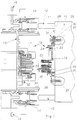
- Figure 1 is a schematic view in elevation and partially in section along the broken line 1-1 of Figure 2 of the withdrawable circuit breaker according to the invention, shown in the withdrawn position.
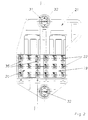
- FIG. 2 is a side view of the withdrawable part of the drawout block according to FIG. 1.
- Figure 3 is a view similar to that of Figure 2 showing the fixed part of the drawout block.
- Figure 4 is a view similar to Figure 1 showing the circuit breaker in the plugged-in position.
- a circuit breaker block 10 carries on its rear face 11 pins 12 of the power conductors.
- the circuit breaker block 10 is capable of being connected to a fixed base 13 or a chassis (not shown) which is fitted with tulip contacts 14 in which the pins 12 engage in the connected position of the circuit breaker block 10, for connecting the circuits of power to output pads 15 carried by the base 13.
- the connection of the auxiliary circuits of the circuit breaker is carried out by a drawout block designated by the general reference 16.
- the drawout block 16 consists of two parts, a first part 17 rigidly fixed to the base 13, and a second conjugate part 18 carried by the rear face 11 of the circuit breaker block 10.
- Such a withdrawable circuit breaker is well known and the assembly is arranged so that, when the circuit breaker block 10 is put in place by racking-in, the electrical connection of the power circuits and the auxiliary circuits is carried out automatically, the disconnection intervening automatically by the movement in breakout of the circuit breaker block 10.
- the second part 18 of the racking-in block 16 consists of several modules, in the example shown of two modules 19.20 juxtaposed on a plate 21 fixed to the circuit breaker block 10.
- the two modules 19.20 are identical and each carries nine plug-in contacts in the cell.
- Each module 19.20 is fixed by snap-fastening on the plate 21, on the one hand by engagement of a tongue 23 under a retaining stop 24 of the plate 21, and on the other hand by snap-fastening of a flange 25 on a latching hook 26 secured to the plate 21.
- the latching system can be arranged differently, provided that it is capable of ensuring correct positioning of the module 19.20 on the plate 21.
- the plate 21 is itself fixed to the circuit breaker block 10 by two screws 27 passing through orifices 28 of the plate and screwing into the wall of the molded case of the circuit breaker block 10.
- the orifices 28 are of a section greater than that of the screw 27 and between the internal periphery of the orifice 28 and the external periphery of the screw 27 are coaxially inserted an elastic sleeve 29, for example made of rubber, and a barrel 30 of a washer 31 threaded onto the screw 27. It is understood that the presence of the elastic sleeve 27 allows re displacement latif, in particular of translation of the plate 21 relative to the circuit breaker block 10.
- the first part 17 of the draw-out block 16 is fixed by screws 32 to the base 13 and it has plug-in pins 33 cooperating with the cells 22 in the plugged-in position of the circuit breaker to ensure the connection of the auxiliary circuits.
- the pins 33 are connected to screw terminals 34 receiving the external connection wires from the withdrawable circuit breaker.
- the parts 17, 18 of the draw-out block 16 have centering pins or pins 35 which, when racked in, correctly position the two parts 17, 18, causing if necessary a deformation of the elastic sleeve 29, in order to compensate for defects alignment.
- the first part 17 of the racking block is in the example illustrated by the figure, consisting of two modules 36, 37 conjugated with modules 19, 20 of the second part, but it is clear that this first part can be in one piece, some racking contacts possibly remaining unused.
- the implementation of the racking device according to the invention is apparent from the preceding description and it suffices to recall that the snap-fastening of the modules 19, 20 can be carried out by the installer, in a particularly simple manner.
- the number of modules 19,20 installed can be adapted to the number of auxiliary circuits of the circuit breaker block, and a subsequent adaptation, for example when adding an additional auxiliary block, can be carried out by simply adding an additional module.
Landscapes
- Engineering & Computer Science (AREA)
- Power Engineering (AREA)
- Breakers (AREA)
- Switch Cases, Indication, And Locking (AREA)
Applications Claiming Priority (2)
| Application Number | Priority Date | Filing Date | Title |
|---|---|---|---|
| FR9213135A FR2697669B1 (fr) | 1992-10-29 | 1992-10-29 | Disjoncteur à bloc de débrochage des circuits auxiliaires. |
| FR9213135 | 1992-10-29 |
Publications (2)
| Publication Number | Publication Date |
|---|---|
| EP0595730A1 true EP0595730A1 (de) | 1994-05-04 |
| EP0595730B1 EP0595730B1 (de) | 1997-08-06 |
Family
ID=9435116
Family Applications (1)
| Application Number | Title | Priority Date | Filing Date |
|---|---|---|---|
| EP19930420407 Expired - Lifetime EP0595730B1 (de) | 1992-10-29 | 1993-10-18 | Schalter mit ausziehbaren Hilfskreisbaugruppen |
Country Status (5)
| Country | Link |
|---|---|
| EP (1) | EP0595730B1 (de) |
| JP (1) | JP3429820B2 (de) |
| DE (1) | DE69312855T2 (de) |
| ES (1) | ES2106992T3 (de) |
| FR (1) | FR2697669B1 (de) |
Cited By (6)
| Publication number | Priority date | Publication date | Assignee | Title |
|---|---|---|---|---|
| US6239395B1 (en) * | 1999-10-14 | 2001-05-29 | General Electric Company | Auxiliary position switch assembly for a circuit breaker |
| US6919785B2 (en) | 2000-05-16 | 2005-07-19 | General Electric Company | Pressure sensitive trip mechanism for a rotary breaker |
| US6995640B2 (en) | 2000-05-16 | 2006-02-07 | General Electric Company | Pressure sensitive trip mechanism for circuit breakers |
| CN103001135A (zh) * | 2012-12-19 | 2013-03-27 | 镇江赛尔尼柯电器有限公司 | 抽屉式配电柜的1/2抽屉单元 |
| CN104362518A (zh) * | 2014-11-28 | 2015-02-18 | 鹤山市辉域成套设备有限公司 | 一种塑壳断路器安装座 |
| CN117995573A (zh) * | 2024-04-03 | 2024-05-07 | 四川电器集团中低压智能配电有限公司 | 一种罐式环保气体绝缘开关设备 |
Families Citing this family (69)
| Publication number | Priority date | Publication date | Assignee | Title |
|---|---|---|---|---|
| IT1292453B1 (it) | 1997-07-02 | 1999-02-08 | Aeg Niederspannungstech Gmbh | Gruppo rotante di contatti per interrutttori di alta portata |
| DE19819242B4 (de) | 1998-04-29 | 2005-11-10 | Ge Power Controls Polska Sp.Z.O.O. | Thermomagnetischer Leistungsschalter |
| US6114641A (en) | 1998-05-29 | 2000-09-05 | General Electric Company | Rotary contact assembly for high ampere-rated circuit breakers |
| US6087913A (en) | 1998-11-20 | 2000-07-11 | General Electric Company | Circuit breaker mechanism for a rotary contact system |
| US6037555A (en) | 1999-01-05 | 2000-03-14 | General Electric Company | Rotary contact circuit breaker venting arrangement including current transformer |
| US6166344A (en) | 1999-03-23 | 2000-12-26 | General Electric Company | Circuit breaker handle block |
| US6262872B1 (en) | 1999-06-03 | 2001-07-17 | General Electric Company | Electronic trip unit with user-adjustable sensitivity to current spikes |
| US6268991B1 (en) | 1999-06-25 | 2001-07-31 | General Electric Company | Method and arrangement for customizing electronic circuit interrupters |
| US6218917B1 (en) | 1999-07-02 | 2001-04-17 | General Electric Company | Method and arrangement for calibration of circuit breaker thermal trip unit |
| US6188036B1 (en) | 1999-08-03 | 2001-02-13 | General Electric Company | Bottom vented circuit breaker capable of top down assembly onto equipment |
| US6252365B1 (en) | 1999-08-17 | 2001-06-26 | General Electric Company | Breaker/starter with auto-configurable trip unit |
| US6710988B1 (en) | 1999-08-17 | 2004-03-23 | General Electric Company | Small-sized industrial rated electric motor starter switch unit |
| US6396369B1 (en) | 1999-08-27 | 2002-05-28 | General Electric Company | Rotary contact assembly for high ampere-rated circuit breakers |
| US6175288B1 (en) | 1999-08-27 | 2001-01-16 | General Electric Company | Supplemental trip unit for rotary circuit interrupters |
| US6232570B1 (en) | 1999-09-16 | 2001-05-15 | General Electric Company | Arcing contact arrangement |
| US6326869B1 (en) | 1999-09-23 | 2001-12-04 | General Electric Company | Clapper armature system for a circuit breaker |
| US6229413B1 (en) | 1999-10-19 | 2001-05-08 | General Electric Company | Support of stationary conductors for a circuit breaker |
| US6317018B1 (en) | 1999-10-26 | 2001-11-13 | General Electric Company | Circuit breaker mechanism |
| US6232856B1 (en) | 1999-11-02 | 2001-05-15 | General Electric Company | Magnetic shunt assembly |
| EP1098343B1 (de) | 1999-11-03 | 2005-09-21 | AEG Niederspannungstechnik GmbH & Co. KG | Drehkontaktanordnung für Schutzschalter |
| US6377144B1 (en) | 1999-11-03 | 2002-04-23 | General Electric Company | Molded case circuit breaker base and mid-cover assembly |
| US6300586B1 (en) | 1999-12-09 | 2001-10-09 | General Electric Company | Arc runner retaining feature |
| US6310307B1 (en) | 1999-12-17 | 2001-10-30 | General Electric Company | Circuit breaker rotary contact arm arrangement |
| US6184761B1 (en) | 1999-12-20 | 2001-02-06 | General Electric Company | Circuit breaker rotary contact arrangement |
| US6172584B1 (en) | 1999-12-20 | 2001-01-09 | General Electric Company | Circuit breaker accessory reset system |
| US6215379B1 (en) | 1999-12-23 | 2001-04-10 | General Electric Company | Shunt for indirectly heated bimetallic strip |
| US6281461B1 (en) | 1999-12-27 | 2001-08-28 | General Electric Company | Circuit breaker rotor assembly having arc prevention structure |
| US6346869B1 (en) | 1999-12-28 | 2002-02-12 | General Electric Company | Rating plug for circuit breakers |
| US6211758B1 (en) | 2000-01-11 | 2001-04-03 | General Electric Company | Circuit breaker accessory gap control mechanism |
| US6239677B1 (en) | 2000-02-10 | 2001-05-29 | General Electric Company | Circuit breaker thermal magnetic trip unit |
| US6429759B1 (en) | 2000-02-14 | 2002-08-06 | General Electric Company | Split and angled contacts |
| US6281458B1 (en) | 2000-02-24 | 2001-08-28 | General Electric Company | Circuit breaker auxiliary magnetic trip unit with pressure sensitive release |
| US6313425B1 (en) | 2000-02-24 | 2001-11-06 | General Electric Company | Cassette assembly with rejection features |
| US6404314B1 (en) | 2000-02-29 | 2002-06-11 | General Electric Company | Adjustable trip solenoid |
| US6204743B1 (en) | 2000-02-29 | 2001-03-20 | General Electric Company | Dual connector strap for a rotary contact circuit breaker |
| US6448521B1 (en) | 2000-03-01 | 2002-09-10 | General Electric Company | Blocking apparatus for circuit breaker contact structure |
| US6340925B1 (en) | 2000-03-01 | 2002-01-22 | General Electric Company | Circuit breaker mechanism tripping cam |
| US6379196B1 (en) | 2000-03-01 | 2002-04-30 | General Electric Company | Terminal connector for a circuit breaker |
| US6346868B1 (en) | 2000-03-01 | 2002-02-12 | General Electric Company | Circuit interrupter operating mechanism |
| US6459349B1 (en) | 2000-03-06 | 2002-10-01 | General Electric Company | Circuit breaker comprising a current transformer with a partial air gap |
| US6211757B1 (en) | 2000-03-06 | 2001-04-03 | General Electric Company | Fast acting high force trip actuator |
| US6496347B1 (en) | 2000-03-08 | 2002-12-17 | General Electric Company | System and method for optimization of a circuit breaker mechanism |
| US6429659B1 (en) | 2000-03-09 | 2002-08-06 | General Electric Company | Connection tester for an electronic trip unit |
| US6218919B1 (en) | 2000-03-15 | 2001-04-17 | General Electric Company | Circuit breaker latch mechanism with decreased trip time |
| US6366188B1 (en) | 2000-03-15 | 2002-04-02 | General Electric Company | Accessory and recess identification system for circuit breakers |
| US6232859B1 (en) | 2000-03-15 | 2001-05-15 | General Electric Company | Auxiliary switch mounting configuration for use in a molded case circuit breaker |
| US6459059B1 (en) | 2000-03-16 | 2002-10-01 | General Electric Company | Return spring for a circuit interrupter operating mechanism |
| US6559743B2 (en) | 2000-03-17 | 2003-05-06 | General Electric Company | Stored energy system for breaker operating mechanism |
| US6586693B2 (en) | 2000-03-17 | 2003-07-01 | General Electric Company | Self compensating latch arrangement |
| US6479774B1 (en) | 2000-03-17 | 2002-11-12 | General Electric Company | High energy closing mechanism for circuit breakers |
| US6472620B2 (en) | 2000-03-17 | 2002-10-29 | Ge Power Controls France Sas | Locking arrangement for circuit breaker draw-out mechanism |
| US6388213B1 (en) | 2000-03-17 | 2002-05-14 | General Electric Company | Locking device for molded case circuit breakers |
| FR2806548B1 (fr) | 2000-03-17 | 2002-08-23 | Ge Power Controls France | Mecanisme extractible pour disjoncteurs |
| US6476698B1 (en) | 2000-03-17 | 2002-11-05 | General Electric Company | Convertible locking arrangement on breakers |
| US6373010B1 (en) | 2000-03-17 | 2002-04-16 | General Electric Company | Adjustable energy storage mechanism for a circuit breaker motor operator |
| US6639168B1 (en) | 2000-03-17 | 2003-10-28 | General Electric Company | Energy absorbing contact arm stop |
| US6747535B2 (en) | 2000-03-27 | 2004-06-08 | General Electric Company | Precision location system between actuator accessory and mechanism |
| US6400245B1 (en) | 2000-10-13 | 2002-06-04 | General Electric Company | Draw out interlock for circuit breakers |
| US6531941B1 (en) | 2000-10-19 | 2003-03-11 | General Electric Company | Clip for a conductor in a rotary breaker |
| US6806800B1 (en) | 2000-10-19 | 2004-10-19 | General Electric Company | Assembly for mounting a motor operator on a circuit breaker |
| US6429760B1 (en) | 2000-10-19 | 2002-08-06 | General Electric Company | Cross bar for a conductor in a rotary breaker |
| US6362711B1 (en) | 2000-11-10 | 2002-03-26 | General Electric Company | Circuit breaker cover with screw locating feature |
| US6380829B1 (en) | 2000-11-21 | 2002-04-30 | General Electric Company | Motor operator interlock and method for circuit breakers |
| US6448522B1 (en) | 2001-01-30 | 2002-09-10 | General Electric Company | Compact high speed motor operator for a circuit breaker |
| US6476337B2 (en) | 2001-02-26 | 2002-11-05 | General Electric Company | Auxiliary switch actuation arrangement |
| US6882258B2 (en) | 2001-02-27 | 2005-04-19 | General Electric Company | Mechanical bell alarm assembly for a circuit breaker |
| US6678135B2 (en) | 2001-09-12 | 2004-01-13 | General Electric Company | Module plug for an electronic trip unit |
| US6469882B1 (en) | 2001-10-31 | 2002-10-22 | General Electric Company | Current transformer initial condition correction |
| US6804101B2 (en) | 2001-11-06 | 2004-10-12 | General Electric Company | Digital rating plug for electronic trip unit in circuit breakers |
Citations (4)
| Publication number | Priority date | Publication date | Assignee | Title |
|---|---|---|---|---|
| US4121067A (en) * | 1977-01-05 | 1978-10-17 | Westinghouse Electric Corp. | Contact structure for drawout switchgear |
| DE3442056A1 (de) * | 1984-11-14 | 1986-05-15 | Siemens AG, 1000 Berlin und 8000 München | Steckverbindervorrichtung |
| EP0236179A1 (de) * | 1986-02-10 | 1987-09-09 | Merlin Gerin | Mechanismus zum Schnappen und Trennen eines elektrischen Schalters mit Haupt- und Hilfsschaltkreisen |
| FR2624312A1 (fr) * | 1987-12-08 | 1989-06-09 | Renault | Connecteur modulaire |
-
1992
- 1992-10-29 FR FR9213135A patent/FR2697669B1/fr not_active Expired - Fee Related
-
1993
- 1993-10-18 EP EP19930420407 patent/EP0595730B1/de not_active Expired - Lifetime
- 1993-10-18 ES ES93420407T patent/ES2106992T3/es not_active Expired - Lifetime
- 1993-10-18 DE DE1993612855 patent/DE69312855T2/de not_active Expired - Lifetime
- 1993-10-20 JP JP26205093A patent/JP3429820B2/ja not_active Expired - Fee Related
Patent Citations (4)
| Publication number | Priority date | Publication date | Assignee | Title |
|---|---|---|---|---|
| US4121067A (en) * | 1977-01-05 | 1978-10-17 | Westinghouse Electric Corp. | Contact structure for drawout switchgear |
| DE3442056A1 (de) * | 1984-11-14 | 1986-05-15 | Siemens AG, 1000 Berlin und 8000 München | Steckverbindervorrichtung |
| EP0236179A1 (de) * | 1986-02-10 | 1987-09-09 | Merlin Gerin | Mechanismus zum Schnappen und Trennen eines elektrischen Schalters mit Haupt- und Hilfsschaltkreisen |
| FR2624312A1 (fr) * | 1987-12-08 | 1989-06-09 | Renault | Connecteur modulaire |
Cited By (9)
| Publication number | Priority date | Publication date | Assignee | Title |
|---|---|---|---|---|
| US6239395B1 (en) * | 1999-10-14 | 2001-05-29 | General Electric Company | Auxiliary position switch assembly for a circuit breaker |
| US6919785B2 (en) | 2000-05-16 | 2005-07-19 | General Electric Company | Pressure sensitive trip mechanism for a rotary breaker |
| US6995640B2 (en) | 2000-05-16 | 2006-02-07 | General Electric Company | Pressure sensitive trip mechanism for circuit breakers |
| CN103001135A (zh) * | 2012-12-19 | 2013-03-27 | 镇江赛尔尼柯电器有限公司 | 抽屉式配电柜的1/2抽屉单元 |
| CN103001135B (zh) * | 2012-12-19 | 2015-08-19 | 镇江赛尔尼柯电器有限公司 | 抽屉式配电柜的1/2抽屉单元 |
| CN104362518A (zh) * | 2014-11-28 | 2015-02-18 | 鹤山市辉域成套设备有限公司 | 一种塑壳断路器安装座 |
| CN104362518B (zh) * | 2014-11-28 | 2016-11-02 | 鹤山市辉域成套设备有限公司 | 一种塑壳断路器安装座 |
| CN117995573A (zh) * | 2024-04-03 | 2024-05-07 | 四川电器集团中低压智能配电有限公司 | 一种罐式环保气体绝缘开关设备 |
| CN117995573B (zh) * | 2024-04-03 | 2024-06-04 | 四川电器集团中低压智能配电有限公司 | 一种罐式环保气体绝缘开关设备 |
Also Published As
| Publication number | Publication date |
|---|---|
| ES2106992T3 (es) | 1997-11-16 |
| EP0595730B1 (de) | 1997-08-06 |
| DE69312855T2 (de) | 1998-01-29 |
| FR2697669A1 (fr) | 1994-05-06 |
| JP3429820B2 (ja) | 2003-07-28 |
| JPH06236727A (ja) | 1994-08-23 |
| DE69312855D1 (de) | 1997-09-11 |
| FR2697669B1 (fr) | 1995-01-06 |
Similar Documents
| Publication | Publication Date | Title |
|---|---|---|
| EP0595730B1 (de) | Schalter mit ausziehbaren Hilfskreisbaugruppen | |
| CA2279619C (en) | Faceplate assembly with self-contained mounting brackets and fastening hardware | |
| US4407559A (en) | Connector device with flush mounting receptacle, cover plate and terminal board | |
| US20020044646A1 (en) | Tool-less wall-mount distributed filter housing | |
| KR850006666A (ko) | 커넥터 장치 | |
| HU223704B1 (hu) | Bővíthető funkcionális fővezeték egység kisfeszültségű villamos kapcsolómezőhöz | |
| EP0407542A1 (de) | Koaxialer steckverbinder für eine gedruckte schaltungsplatte. | |
| EP2456051B1 (de) | Frequenzumrichter zum Steuern eines Elektromotors | |
| US5333099A (en) | Electrical component having a sandwich-like sub-assembly | |
| GB2311381A (en) | Equipment modules and backplane with optical connection | |
| BE1001662A5 (fr) | Armoire de commande prefabriquee. | |
| BE1006273A3 (fr) | Boite de connexion pour telecommunications. | |
| BE1015544A5 (fr) | Dispositif d'intercommunication. | |
| CN117438823A (zh) | 一种避免接线松动的端子连接器 | |
| DK0818072T3 (da) | Anordning til tilslutning af elektriske installationsapparater | |
| CN223052462U (zh) | 一种具有防水功能的信号传输连接器 | |
| JPS6342451Y2 (de) | ||
| US10043626B1 (en) | Electrical switching apparatus assembly, and module assembly and operating method therefor | |
| JP4661432B2 (ja) | 引出形回路遮断器 | |
| CN112614708A (zh) | 一种具有电缆线去皮以及裁剪功能的开关机构 | |
| CN220453539U (zh) | 一种安装便捷的橱柜灯 | |
| JPH085587Y2 (ja) | 電子機器構造 | |
| EP3909064B1 (de) | Anschlussleiste | |
| MY121506A (en) | Electric combination connector set | |
| KR20010088409A (ko) | 전기 장치 및 전기 장치와 램프 터브를 구비한 유닛 |
Legal Events
| Date | Code | Title | Description |
|---|---|---|---|
| PUAI | Public reference made under article 153(3) epc to a published international application that has entered the european phase |
Free format text: ORIGINAL CODE: 0009012 |
|
| AK | Designated contracting states |
Kind code of ref document: A1 Designated state(s): DE ES GB IT |
|
| 17P | Request for examination filed |
Effective date: 19941118 |
|
| RAP1 | Party data changed (applicant data changed or rights of an application transferred) |
Owner name: SCHNEIDER ELECTRIC SA |
|
| GRAG | Despatch of communication of intention to grant |
Free format text: ORIGINAL CODE: EPIDOS AGRA |
|
| 17Q | First examination report despatched |
Effective date: 19961017 |
|
| GRAH | Despatch of communication of intention to grant a patent |
Free format text: ORIGINAL CODE: EPIDOS IGRA |
|
| GRAH | Despatch of communication of intention to grant a patent |
Free format text: ORIGINAL CODE: EPIDOS IGRA |
|
| GRAA | (expected) grant |
Free format text: ORIGINAL CODE: 0009210 |
|
| AK | Designated contracting states |
Kind code of ref document: B1 Designated state(s): DE ES GB IT |
|
| REF | Corresponds to: |
Ref document number: 69312855 Country of ref document: DE Date of ref document: 19970911 |
|
| GBT | Gb: translation of ep patent filed (gb section 77(6)(a)/1977) |
Effective date: 19970919 |
|
| ITF | It: translation for a ep patent filed | ||
| REG | Reference to a national code |
Ref country code: ES Ref legal event code: FG2A Ref document number: 2106992 Country of ref document: ES Kind code of ref document: T3 |
|
| PLBE | No opposition filed within time limit |
Free format text: ORIGINAL CODE: 0009261 |
|
| STAA | Information on the status of an ep patent application or granted ep patent |
Free format text: STATUS: NO OPPOSITION FILED WITHIN TIME LIMIT |
|
| 26N | No opposition filed | ||
| REG | Reference to a national code |
Ref country code: GB Ref legal event code: IF02 |
|
| PGFP | Annual fee paid to national office [announced via postgrant information from national office to epo] |
Ref country code: GB Payment date: 20021016 Year of fee payment: 10 |
|
| PG25 | Lapsed in a contracting state [announced via postgrant information from national office to epo] |
Ref country code: GB Free format text: LAPSE BECAUSE OF NON-PAYMENT OF DUE FEES Effective date: 20031018 |
|
| PGFP | Annual fee paid to national office [announced via postgrant information from national office to epo] |
Ref country code: ES Payment date: 20031128 Year of fee payment: 11 |
|
| GBPC | Gb: european patent ceased through non-payment of renewal fee |
Effective date: 20031018 |
|
| PG25 | Lapsed in a contracting state [announced via postgrant information from national office to epo] |
Ref country code: ES Free format text: LAPSE BECAUSE OF NON-PAYMENT OF DUE FEES Effective date: 20041019 |
|
| REG | Reference to a national code |
Ref country code: ES Ref legal event code: FD2A Effective date: 20041019 |
|
| PGFP | Annual fee paid to national office [announced via postgrant information from national office to epo] |
Ref country code: DE Payment date: 20091010 Year of fee payment: 17 |
|
| PGFP | Annual fee paid to national office [announced via postgrant information from national office to epo] |
Ref country code: IT Payment date: 20091017 Year of fee payment: 17 |
|
| REG | Reference to a national code |
Ref country code: DE Ref legal event code: R119 Ref document number: 69312855 Country of ref document: DE Effective date: 20110502 |
|
| PG25 | Lapsed in a contracting state [announced via postgrant information from national office to epo] |
Ref country code: IT Free format text: LAPSE BECAUSE OF NON-PAYMENT OF DUE FEES Effective date: 20101018 |
|
| PG25 | Lapsed in a contracting state [announced via postgrant information from national office to epo] |
Ref country code: DE Free format text: LAPSE BECAUSE OF NON-PAYMENT OF DUE FEES Effective date: 20110502 |