EP0595828B1 - Kommunikationseinrichtung und bilddatenübertragungsverfahren von einem sender zu einem oder mehreren empfängern - Google Patents
Kommunikationseinrichtung und bilddatenübertragungsverfahren von einem sender zu einem oder mehreren empfängern Download PDFInfo
- Publication number
- EP0595828B1 EP0595828B1 EP92912587A EP92912587A EP0595828B1 EP 0595828 B1 EP0595828 B1 EP 0595828B1 EP 92912587 A EP92912587 A EP 92912587A EP 92912587 A EP92912587 A EP 92912587A EP 0595828 B1 EP0595828 B1 EP 0595828B1
- Authority
- EP
- European Patent Office
- Prior art keywords
- data
- receiver
- set forth
- sourcing
- signal
- Prior art date
- Legal status (The legal status is an assumption and is not a legal conclusion. Google has not performed a legal analysis and makes no representation as to the accuracy of the status listed.)
- Expired - Lifetime
Links
Images



Classifications
-
- G—PHYSICS
- G09—EDUCATION; CRYPTOGRAPHY; DISPLAY; ADVERTISING; SEALS
- G09B—EDUCATIONAL OR DEMONSTRATION APPLIANCES; APPLIANCES FOR TEACHING, OR COMMUNICATING WITH, THE BLIND, DEAF OR MUTE; MODELS; PLANETARIA; GLOBES; MAPS; DIAGRAMS
- G09B5/00—Electrically-operated educational appliances
- G09B5/08—Electrically-operated educational appliances providing for individual presentation of information to a plurality of student stations
- G09B5/14—Electrically-operated educational appliances providing for individual presentation of information to a plurality of student stations with provision for individual teacher-student communication
-
- G—PHYSICS
- G06—COMPUTING OR CALCULATING; COUNTING
- G06F—ELECTRIC DIGITAL DATA PROCESSING
- G06F15/00—Digital computers in general; Data processing equipment in general
- G06F15/16—Combinations of two or more digital computers each having at least an arithmetic unit, a program unit and a register, e.g. for a simultaneous processing of several programs
- G06F15/163—Interprocessor communication
- G06F15/173—Interprocessor communication using an interconnection network, e.g. matrix, shuffle, pyramid, star, snowflake
- G06F15/17337—Direct connection machines, e.g. completely connected computers, point to point communication networks
Definitions
- This invention relates generally to data communication apparatus and method and, in particular, to apparatus and method for rapidly transferring large blocks of data, such as image data.
- a single computer generated image of medium resolution for example 1024 horizontal by 1024 vertical picture elements (pixels), each having eight bits per red, green and blue color, requires approximately three million bytes (3 MB) of data to express. Transferring such a large data file between data processors, such as workstations, places a significant burden on conventional high-speed serial networks.
- HPPI interface specification provides for transfers of 100M bytes/second using a 32-bit port, or 200M bytes/second if a 64-bit port is used. This particular interface technology is thus particularly attractive for use in transferring, by example, digital image animations between workstations.
- the HPPI interface is intended as a point-to-point, simplex interface between mainframe computers, or between a mainframe and a high-speed disk storage system.
- the distance between nodes is limited to 25 meters and connections between multiple nodes, so as to provide broadcast or multicast transmissions, is not intended.
- each workstation supports the electrical and signal protocols required of a physical channel receiver, and also regenerates and retransmits these signals to another downstream-connect workstation.
- a server which is source of image data, generates the signaling protocols of a transmitter in order to control the data channel.
- the workstations which implement data receivers, retransmit the data and signaling protocols generated by the server to downstream receivers.
- each workstation provides retransmission of any handshaking signals from a downstream workstation to an upstream workstation, or to the server.
- upstream workstations synchronize locally generated handshaking signals with handshaking signals received from downstream workstations so as to maintain data order integrity and to ensure that all addressed workstations are prepared to receive a transmission from the server.
- the signaling protocol of the physical channel provides selective addressing of individual receivers by the server to provide multicasting.
- This addressing may be implemented as either a connection based switching mechanism or provided on a data block basis, such that each logical data block contains the addresses of the intended receivers.
- a packet of data bursts is defined to correspond to either a complete image frame, or to a rectangular subsection thereof, referred to as a window.
- a first burst is defined to be a Header burst and contains an Image Header that specifies addresses of addressed workstations. Following the Header burst are image data bursts containing pixel data organized in raster format.
- a high-speed multicasting network is implemented utilizing the High-Performance Parallel Interface (HPPI) as the physical channel and is referred to as a HPPI Daisy Chain.
- Document EP-A-0 079 159 discloses a sender connected in a daisy-chain to a number of receivers (page 7, lines 10-22). It further discloses the concept that a receiver transmit a ready signal to its successor only when it is itself ready and has received a ready signal from its predecessor (page 7, lines 22-34).
- the server includes both a HPPI receiver and transmitter.
- the workstations support a full HPPI receiver, but require only a simplified HPPI output port instead of a HPPI transmitter.
- the workstations are connected such the receiver port of each is driven by data and control signals from the upstream server HPPI transmitter port, for the first workstation of the Daisy Chain, or the upstream workstation HPPI output port for all other workstations of the Daisy Chain. Handshaking signals, generated by the receiver ports, ripple upstream to the server or to an upstream workstation output port.
- An optional loop-back connection between the last workstation in the chain and the server may also be included.
- the loop-back connection provides a means for performing network diagnostics and testing.
- the network supports 32 workstations, each placed a maximum of 25 meters from one another. These distances may be extended by use of signal repeater units placed between workstations.
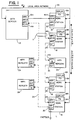
- Fig. 1 illustrates a high speed network 10 that is constructed and operated in accordance with the invention.
- Network 10 employs a communication bus that conforms to the aforementioned HPPI specification as a physical communications channel 11, also referred to herein as a HPPI Daisy Chain.
- a data server 12 includes both a HPPI receiver 14a and a HPPI transmitter 16a.
- the data server 12 may be a supercomputer that generates image data.
- a plurality of workstations 18 are connected to the HPPI Daisy Chain 11. Each workstation 18 typically includes or controls a frame buffer (FB) 18a and a display 18b for visualizing the image data generated by the data server 12.
- FB frame buffer
- Each workstation 18 also includes a HPPI receiver 14b, but is not required to implement a HPPI transmitter.
- each workstation 18 is provided with a HPPI output port 20.
- the workstations 18 are coupled together such that the receiver port 14b of each is driven by data and control signals from the upstream server 12 HPPI transmitter 16a or the upstream workstation 18 output port 20.
- Handshaking signals, generated by each of the workstation 18 output ports 20 are directed upstream to the server 12, or to an upstream workstation 18 HPPI output port 20, depending on the physical location of the workstation within the HPPI Daisy Chain 11.
- Fig. 1 also illustrates an optional loop-back connection 22 between a last workstation, designated 18 L , and the server 12.
- the HPPI loop-back connection 22 provides a means for performing network diagnostics and testing by enabling the server 12 to transmit a message to the workstations 18 and to receive information therefrom.
- the network 10 in a present embodiment, supports 32 of the workstations 18, each positioned a maximum of 25 meters from one another. These distances may be extended by the use of Repeater Units 24 of a type described in detail below and illustrated in Fig. 7.
- a local area network (LAN) 26 is also coupled between the data server 12 and the workstations 18 to resolve any contentions for access to the HPPI physical communications channel 11 and to perform other functions, such as notifying the server 12 of image data requests, error conditions, and other events.
- LAN 26 embodiment is a Token Ring.
- the network 10 thus provides a forward, high speed HPPI data path for image data from the server 12 to each workstation 18.
- a slower return path from the workstations 18 to the server 12 is implemented using the LAN 26.
- a logical bit-addressing mechanism contained in a data word of each image file, provides the server 12 the ability to provide broadcast (all workstations), multicast (some workstations) or singlecast (one workstation) transfers.
- the server 12 issues a Logical Unit Number (LUN) to each workstation 18 in the HPPI Daisy Chain 11.
- LUN Logical Unit Number
- This LUN is stored in a HPPI address comparator and is employed to match against a bit-address of an incoming data file. If matched, the data is placed in the workstation 18 FB 18a for display.
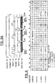
- Fig. 3a for showing an illustrative timing diagram of a synchronous transfer of three data bursts from a source (S) to a destination (D) in accordance with the HPPI specification.
- Each data burst has associated therewith a length/longitudinal redundancy checkword (LLRC) that is sent from the source to the destination on a 32-bit data bus during a first clock period following a data burst.
- LLRC length/longitudinal redundancy checkword
- Packets of data bursts are delimited by a PACKET signal being true.
- the BURST signal is a delimiter marking a group of words on the HPPI data bus as a burst.
- the BURST signal is asserted by the source with the first word of the burst and is deasserted with the final word. Each burst may contain from one to 256 32-bit data words.
- a REQUEST signal is asserted by the source to notify the destination that a connection is desired.
- the CONNECT signal is asserted by the destination in response to a REQUEST.
- One or more READY indications are sent by the destination after a connection is established, that is, after CONNECT is asserted.
- the destination sends one ready indication for each burst that it is prepared to accept from the source.
- a plurality of READY indications may be sent from the destination to the source to indicate a number of bursts that the destination is ready to receive.
- a CLOCK signal defined to be a symmetrical signal having a period of 40 nanoseconds (25 MHz) and which is employed to synchronously time the transmission of data words and the various control signals.
- the HPPI-PH specification defines a hierarchy for data transfers, where a data transfer is composed of one or more data packets. Each packet is composed of one or more data bursts. Bursts are composed of not more than 256 32-bit data words, clocked at 25MHz. Error detection is performed across a data word using odd parity on a byte basis. Error detection is performed longitudinally, along a bit column in the burst, using even parity, and is then appended to the end of the burst. Bursts are transmitted on the ability of a receiver to store or otherwise absorb a complete burst. The receiver notifies the transmitter of its ability to receive a burst by issuing the Ready signal.
- the HPPI-PH specification allows the HPPI-PH transmitter to queue up 63 Ready signals received from a receiver.
- Fig. 3b illustrates an adaptation to the HPPI data format of Fig. 3a, in accordance with an aspect of the invention, to accomplish image data transfers.
- a packet of data bursts corresponds to either a complete image frame, or to a rectangular subsection thereof, referred to as a window.
- the packet includes two or more bursts.
- a first burst is defined to be a Header burst and contains generic HPPI device information, the HPPI Header, and also image data information, referred to herein as an Image Header. The remainder of the Header burst is presently unused.
- Pixel data is organized in raster format, that is the left-most pixel of a top display scanline is the first word of the first data burst. This ordering continues until the last pixel of the last scanline. The last burst is padded, if required, to full size.
- Each data word contains 8-bits of red, green, and blue (RGB) color information for a specific pixel.
- RGB red, green, and blue
- the remaining 8-bits of each 32-bit data word may be employed in several manners. For systems capable of linearly mixing two images, the additional 8-bits may be used to convey key, or alpha, data for determining the contribution of each input image to a resulting output image.
- Another use of a portion of the additional 8-bits of each data word is to assign two additional bits to each color for frame buffers capable of supporting 10-bits of RGB data. Also, a number of data packing techniques may be employed wherein the additional 8-bits of each word are used to increase the effective HPPI image transfer bandwidth by one third, when using 24-bit/pixel images.
- Fig. 4 illustrates in greater detail the organization of the Image Header of Fig. 3b.
- a HPPI Bit Address to which specific workstations 18 respond, is the first word of the Image Header. In that the data word is 32-bits wide, a maximum of 32 unique workstation addresses may be specified.
- a control/status word used to communicate specific image/packet information to the workstation. This includes a bit for indicating if the pixel data is compressed (C), a bit for indicating if the associated Packet is a last packet (L) of a given frame (EOF), and an Interrupt signal (I) which functions as an ATTENTION signal.
- the last two words of the Image Header (X-DATA and Y-DATA) contain size (length) and location (offset) information for the x and y image directions.
- x-length and y-length may both equal 1024, for a 1024 x 1024 resolution screen, and the offsets are both zero.
- x-length and y-length indicate the size of the window and the two offsets indicate the position of the upper-left most corner of the window, relative to a screen reference point.
- the screen reference point is the top-left most pixel.
- Fig. 5 is a block diagram showing a workstation 18 Daisy Chain port.
- Functional blocks include input registers 30, a clock phase-locked loop (PLL) 32, Parity/LLRC Checker 34, FIFO memory 36, HPPI Address Comparator 38, Ready Queue 40 and a Connect/Ready Regenerator 42.
- PLL clock phase-locked loop
- the input registers 30 include a first set of D-registers 30a, clocked by an inverted HPPI input clock (CLKi) so as to store received data (D ⁇ 31:0>), parity (P ⁇ 3:0>), and control bits (REQUEST, PACKET, BURST) for each CLKi cycle.
- CLKi inverted HPPI input clock
- the data, parity, and control information are also stored in a second set of D-registers 30b which are clocked by an output clock (CLKo).
- CLKo is frequency and phase stable and locked to CLKi by the PLL 32 to ensure that CLKo maintains a specific phase relation to CLKi, given a restricted frequency deviation of CLKi.
- the PLL 32 thus guards against isolated, missing, or extra input clocks, since the PLL 32 is relatively insensitive to momentary input signal instabilities.
- Parity/LLRC Detector 34 Following the CLKo D-registers is the Parity/LLRC Detector 34, the HPPI Address Comparator 38, and the FIFO memory buffer 36.
- the Parity/LLRC Detector 34 generates a maskable error interrupt to the workstation 18 processor (not shown) which, as stated above, reports the occurrence of the error back to the server 12 via the LAN 26.
- the workstation 18 may also request, via the LAN 26, a retransmission of an erroneously received image data packet.
- a FIFO controller 36 is coupled to an ERROR signal output by Parity/LLRC Detector 34 to prevent writing image data to the FIFO memory 36 if a Header Burst error is detected.
- the HPPI Address Comparator 38 asserts an Internal Connect (INTCNCT) signal if an address for the workstation 18 is detected in the incoming packet's bit address word (Fig. 4).
- a 5-bit address code is held by a writable register within the comparator 38, the 5-bit code being writable by the workstation 18 processor.
- the 5-bit code identifies which of the 32-bits of the bit address word correspond to the workstation.
- the data server 12 is enabled to dynamically reconfigure the HPPI addresses of the workstations 18. This is a useful feature of the invention, in that workstations 18 may be added to or deleted from the HPPI Daisy Chain 11 with minimal delay.
- INTCNCT (with no Header Error) to the FIFO Controller 36a enables writing of the packet's data bursts into the FIFO memory 36.
- the FIFO memory 36 has the capacity to store N data bursts.
- Data is extracted from the FIFO 36 by means of a RDCLK signal generated by the workstation 18. The extracted data is transferred to the FB 18a for display.
- the FIFO Controller 36a issues an Internal Ready (INTREADY) signal.
- the Ready signal would immediately be sent to the server.
- the HPPI Daisy Chain receiver 14b of the invention operates in a different manner. Specifically, the INTREADY signal is placed in the Internal Ready Queue 40.
- the input HPPI data, parity, and control signals are clocked into the second set of D-registers 30b by CLKo.
- the outputs of these registers, and a buffered CLKo, are applied to the output port 20 and drive the downstream extension of the HPPI bus, via a set of output registers 44.
- output registers 44 are optional. However, their use is preferred so as to minimize bit skew and maintain HPPI-PH specification timing tolerances to downstream HPPI receivers 14b.
- Fig. 6 illustrates in greater detail the Ready Queue 40 and the Connect/Ready Regenerate logic 42 of Fig. 5.
- one function of the Ready Queue 40 is to store Internal Ready signals that generated by the FIFO controller 36a.
- the INTREADY signals are stored within the block INTQUEUE 46, which is preferably implemented with a 64 location by one bit (64 X 1) FIFO.
- Another portion of the Ready Queue 40 is an External Ready Queue (EXTQUEUE) 48 which stores incoming Ready signals received from downstream receivers 14b.
- EXTQUEUE 48 is also preferably implemented with a 64 X 1 FIFO.
- the Ready Regenerator 50 immediately issues a Ready when one enters the INTQUEUE 46.
- the rate at which the last receiver 14b of the HPPI Daisy Chain issues Ready signals is determined by the state of INTCNCT and the rate at which the associated data FIFO 36 is emptied. If INTCNCT is false, Internal Readys are issued by the FIFO Controller 36a when the HPPI Burst signal transitions from a true state to false state, that is, at the end of a Burst. If INTCNCT is true, Internal Readys are issued only when there is sufficient free memory in the FIFO 36 to accept another Burst. The last workstation 18 L of the HPPI Daisy Chain is therefore the source of all cascading Ready signals.
- Upstream workstations that is those which are interposed between the server 12 and the last workstation 18 L , delay issuing a Ready signal until an externally generated Ready signal is stored in the EXTQUEUE 48. With CNCTD2S true, and if INTQUEUE 46 also contains a Ready, both queues are considered to be ready and a Ready signal is sent to the Regenerator 42 for transmission to an upstream receiver 14b.
- the rate at which Ready signals are issued is determined by the availability of the FIFO 36 at each addressed workstation 18.
- a workstation 18 having a slowest FIFO 36 read rate thus paces the network and determines when Readys cascade upstream.
- the function of the Connect/Ready Regenerator 42 is two fold.
- the Ready Regenerator 50 pulse shapes the outgoing Ready in order to maintain HPPI-PH specifications for this signal.
- the Ready Regenerator 50 is implemented as a shift register and assures that the outgoing Ready signal is eight 25MHz clock periods wide.
- the Terminal Count (Tc) output of the Ready Regenerator 50 also functions to clock the output ports of the INTQUEUE and EXTQUEUE FIFOs 46 and 48.
- a Connect signal which is issued by each workstation 18 in response to a Request signal from the server 12 (Fig. 8), also cascades up from the last workstation 18 to the server 12.
- the Connect signal notifies the server 12 that packet transmissions may begin.
- a Connect Regenerator (not shown in Fig. 6) reforms the leading edge of the Connect signal and gates the onboard Connect with the incoming External Connect from a downstream workstation 18.
- the number of Readys issued to the server 12 at the initiation of a Connect is determined by the workstation 18 having the least amount of FIFO 36 memory storage.
- the workstation 18 having the least amount of FIFO 36 memory storage By example, if the last workstation 18 is capable of accepting 63 data bursts, and had issued 63 Ready signals after connecting, an intermediate workstation 18 having only a single burst sized FIFO 36 stores 62 of the incoming 63 Ready signals within its EXTQUEUE 48. The first of the 63 incoming External Ready signals is gated with the single Internal Ready signal and is propagated upstream.
- Fig. 7 is a block diagram of one of the HPPI Repeater Units 24 used to extend cabling distances between HPPI ports above 25 meters.
- the Repeater Unit 24 may be employed to overcome distance constraints between any two HPPI devices, whether connected in the Daisy Chain configuration or connected in a conventional HPPI point-to-point manner.
- the Repeater Unit 24 may also be used to temporarily replace or bridge around a daisy chained workstation 18 that is not currently operational.
- networks using the loop-back configuration may employ one or more Repeater Units 24 to duplicate the out-going cable path in the return path to the server 12, thereby minimizing workstation placement constraints.
- the Repeater Unit 24 includes the input buffers 30a, output buffers 44, PLL 32, and the Connect/Ready Regenerator 42 of Fig. 6 to input the HPPI data, parity, and control lines, resynchronize these signals, and transmit same to the next Repeater Unit 24, workstation 18, or to the server 12.
- Fig. 2 illustrates a further HPPI Daisy Chain topology, whereby data transfers cascade from one workstation 18 to another through a single HPPI channel 30 using the packet format shown in Figs. 3 and 4.
- HPPI networking protocols and mechanisms are implemented in each workstation 18, which minimally support a HPPI receiver 14b, and a HPPI transmitter 16b for transferring data downstream.
- HPPI handshaking signals Ready and Connect are transferred from downstream workstations 18 to upstream workstations.
- the workstations 18 are connected in a ring configuration, such that any workstation 18 can source data to any other workstation 18 or to all other workstations 18. Contention for access to the HPPI channel is resolved using communications across the low-speed LAN path 26.
- Fig. 2 requires minimal additional hardware in addition to the HPPI receiver 14b and transmitter 16b in each workstation 18.
- Fig. 2 Although the embodiment of Fig. 2 is well suited for its intended use, in applications where the data server 12 is rendering or otherwise generating image data for a number of receive-only graphic workstations, the HPPI Daisy Chain is simplified by replacing the HPPI transmitter 16b in the workstations 18 with the relatively simple output port 20, as depicted in Figs. 1 and 5.
- the output port 20 need only latch the data and control signals from the receiver port 14b before retiming the signals to meet HPPI specifications. This approach thus provides an economical solution for rapidly transferring large image data files from workstation to workstation.
- the embodiment of Figs. 1 and 5, as described in detail above, is thus presently preferred.
- the teaching of the invention provides that broadcast, multicast, or singlecast modes of transmission are transparent to each of the image data receivers and are performed using the same circuitry. Furthermore, through the use of the daisy-chained Ready signals, multiple data bursts may exist on the network and receivers with different size data FIFOs may be connected together without losing synchronization. No specialized bus controllers are required and no arbitration is necessary, as is the case for many communication techniques.
- the image data receivers are not required to access the communications bus in that the separately provided LAN 26 may be employed for sending status or other information to the data server 12. Furthermore, only communication bus control signals, such as Ready, are daisy-chained through the image data receivers.
Landscapes
- Engineering & Computer Science (AREA)
- Computer Hardware Design (AREA)
- Physics & Mathematics (AREA)
- Theoretical Computer Science (AREA)
- General Physics & Mathematics (AREA)
- Business, Economics & Management (AREA)
- General Engineering & Computer Science (AREA)
- Software Systems (AREA)
- Mathematical Physics (AREA)
- Educational Administration (AREA)
- Educational Technology (AREA)
- Small-Scale Networks (AREA)
- Computer And Data Communications (AREA)
- Data Exchanges In Wide-Area Networks (AREA)
- Details Of Television Systems (AREA)
- Television Systems (AREA)
- Image Input (AREA)
- Communication Control (AREA)
Claims (23)
- Eine Methode zur Übertragung von Daten von einem Ursprung (12) zu einem oder mehreren einer Vielzahl von Empfängern (18), die über parallele Kommunikationsbus-Mittel (11) in einer Verkettung miteinander gekoppelt sind, bei der einzelne der Empfänger (18) an das Kommunikationsbus-Mittel (11) gekoppelt sind und einen Empfängerport (14b) zum Empfang von Signalen von dem Kommunikationsbus-Mittel (11) und einen Ausgangsport (20) zur Bereitstellung von Signalen an den Empfängerport (14b) eines nächsten Empfängers (18) aufweisen, wobei die Daten in Eins bis N Blöcken übertragen werden, wobei N mindestens 2 ist, und mindestens einer der Empfänger (18) mehr als einen Block puffern kann, wobei die genannte Methode durch folgende Schritte gekennzeichnet ist:mit jedem der Empfänger (18), Erzeugen von einem bis mindestens N internen Bereit-Signalen, wobei die Anzahl der erzeugten internen Bereit-Signale eine Funktion einer Anzahl der Blöcke ist, welche der Empfänger (18) puffern kann;Speichern der erzeugten ein bis mindestens N internen Bereit-Signale in dem Empfänger (18); undFeststellen, ob ein Downstream-Empfänger (18), falls ein solcher vorhanden ist, mindestens ein externes Bereit-Signal erzeugt hat, welches anzeigt, daß der Downstream-Empfänger (18) bereit ist, Daten zu empfangen; wobeiwenn kein Downstream-Empfänger (18) vorhanden ist, Erzeugen eines externen Bereit-Signals für jedes der gespeicherten internen Bereit-Signale und Übertragung desselben an einen Upstream-Empfänger (18), falls ein solcher vorhanden ist, oder, wenn nicht, Übertragen des (der) erzeugten externen Bereit-Signals zum Ursprung (12);wenn der Downstream-Empfänger (18) nicht mindestens ein externes Bereit-Signal erzeugt hat, Verweilen im Ruhezustand, bis der Downstream-Empfänger (18) mindestens ein externes Bereit-Signal erzeugt;wenn der Downstream-Empfänger (18) mindestens ein externes Bereit-Signal erzeugt hat, Empfangen und Speichern des mindestens einen externen Bereit-Signals, welches von dem Downstream-Empfänger (18) erzeugt wird, Erzeugen eines externen Bereit-Signals für jedes gespeicherte interne Bereit-Signal, das ein entsprechendes gespeichertes externes Bereit-Signal hat, und Übertragen des mindestens einen erzeugen externen Bereit-Signals an den Upstream-Empfänger (18), falls ein solcher vorhanden ist, oder, wenn nicht, Übertragen des mindestens einen erzeugten externen Bereit-Signals zum Ursprung (12).
- Eine Methode nach Anspruch 1 und folgende Schritte umfassend:mit dem Ursprung (12) der Daten, Empfangen des externen Bereit-Signals oder der externen Bereit-Signale und, in Antwort auf diese, Übertragen von Informationen zum Kommunikationsbus-Mittel (11), um einen oder mehrere der Empfänger (18) zu adressieren; undmit jedem der adressierten Empfänger (18), Empfangen der vom Kommunikationsbus-Mittel (11) übertragenen Information.
- Eine Methode nach Anspruch 2, bei der der Schritt der Informationsübertragung folgenden Schritt umfaßt:
Übertragung eines aus Datenworten bestehenden Datenbündels, wobei mindestens eines der Worte ein Adressenwort angibt, das aus einer Vielzahl von Bits besteht, von denen einzelne, wenn sie geltend gemacht werden, einen der Empfänger (18) identifizieren. - Eine Methode nach Anspruch 2 oder 3, bei der der Schritt, in dem Informationen empfangen werden, folgenden Schritt umfaßt:
Feststellen, ob ein bestimmtes Bit, das von einem gespeicherten Adressenbit-Spezifizierer angegeben wird, geltend gemacht wird, und, wenn dies der Fall ist, Erzeugen eines Signals, welches anzeigt, daß der Empfänger (18) adressiert wird. - Eine Methode nach einem der Ansprüche 1 bis 4 und in Reaktion auf den Empfang eines anderen empfangenen externen Bereit-Signals durch den Ursprung (12) der Daten, den Schritt der Übertragung von Daten zum Kommunikationsbus-Mittel (11) umfassend, wobei die Daten als ein Bündel übertragen werden, das aus einer Vielzahl von Datenworten besteht, wobei jedes Datenwort Merkmale mindestens eines Bild-Pixels angibt.
- Eine Methode nach Anspruch 5, bei der jedes der Vielzahl von Datenworten aus 32 Bits besteht und bei der ein bestimmtes Bild-Pixel-Merkmal 24 Bits zur Spezifikation der roten, grünen und blauen Pixel-Farbe erfordert.
- Eine Methode nach Anspruch 6, bei der eine verbleibende Anzahl von Bits von jedem der Vielzahl von Datenworten einen Wert angibt, der zum Mischen des Bild-Pixels mit einem anderen Bild-Pixel eingesetzt wird.
- Eine Methode nach einem der Ansprüche 6 oder 7, bei der der Bildkopf weiter eine Größe und eine Lage eines Anzeigebildfensters angibt, wobei das Anzeigebildfenster aus einer Vielzahl von Bild-Pixeln besteht, die von dem mindestens einen weiteren Bündel angegeben werden.
- Eine Methode nach einem der Ansprüche 2 bis 8, bei der der Schritt des Informationsempfangs von dem Kommunikationsbus-Mittel (11) den Schritt des Speicherns der Information in einem FIFO-Puffer-Mittel umfaßt.
- Eine Methode nach Anspruch 9, und den Schritt umfassend, in dem, mit adressierten Empfängern (18), bestimmt wird, ob ein Datenspeichermittel eine ausreichende Anzahl von ungenutzten Speicherplätzen hat, um ein Datenbündel zu speichern, wobei das Datenbündel aus einer vorbestimmten Anzahl von Datenworten besteht.
- Eine Methode nach Anspruch 10, bei der die vorbestimmte Zahl 256 ist.
- Eine Methode nach einem der Ansprüche 2 bis 11, bei der in dem Informationsübertragungsschritt eine Vielzahl von Datenworten übertragen wird, die eine Größe und eine Lage eines Anzeigebildfensters angeben.
- Ein System zum Anzeigen von Daten mit einer Vielzahl von Anzeigemitteln, folgendes umfassend:Mittel (12) zum Absenden von Daten als Paket mit bis zu N Datenblöcken, wobei N mindestens 2 ist;eine Vielzahl von Empfängermitteln (18), wobei mindestens eines der Empfängermittel (18) mehr als einen Block puffern kann; undparallele Kommunikationsbus-Mittel (11), welche das Absendemittel (12) und die Vielzahl von Empfängermitteln (18) in einer Verkettung miteinander koppeln, um Daten von dem Absendemittel (12) in Downstream-Richtung zu einem oder mehreren der Vielzahl von Empfängermitteln (18) zu übertragen, wobei einzelne Empfängermittel (18) mit dem Kommunikationsbus-Mittel (11) gekoppelt sind und einen Empfängerport (14b) zum Empfang von Signalen von dem Kommunikationsbus-Mittel (11) und einen Ausgangsport (20) umfassen, der dem Empfängerport (14b) eines nächsten Empfängermittels (18) Signale bereitstellt;wobei das genannte System dadurch gekennzeichnet ist, daß:jedes der Empfängermittel (18) folgendes umfaßt:Mittel zum Erzeugen und Speichern einer Anzeige der Fähigkeit, bis zu N Datenblöcke von dem Absendemittel (12) zu empfangen;Mittel zum Empfangen und Speichern einer Anzeige der Fähigkeit eines in Downstream-Richtung liegenden Empfängermittels (18), bis zu N Datenblöcke von dem Absendemittel (12) zu empfangen; undMittel, das auf das Vorhandensein einer erzeugten und gespeicherten Anzeige der Fähigkeit, mindestens einen Datenblock von dem Absendemittel (12) zu empfangen und auch auf eine empfangene und gespeicherte Anzeige von dem im Downstream liegenden Empfängermittel (18), daß es mindestens einen Datenblock von dem Absendemittel (12) empfangen kann, reagiert, um in Upstream-Richtung zum Absendemittel (12) bis zu Y Signale übertragen, welche die Fähigkeit anzeigen, bis zu Y Datenblöcke von dem Absendemittel (12) zu empfangen, wobei Y der geringeren der erzeugten und gespeicherten Anzeige oder der empfangenen und gespeicherten Anzeige entspricht, und wobei Y = N, wenn die erzeugte und gespeicherte Anzeige und die empfangene und gespeicherte Anzeige beide gleich N sind.
- Ein System nach Anspruch 13, bei dem das Absendemittel (12) ein Kommunikationsbus-Sendemittel enthält, um Datenworte parallel an das Kommunikationsbus-Mittel (11) zu übertragen.
- Ein System nach Anspruch 14, bei dem das Sendemittel Mittel umfaßt, um ein Anforderungssignal auf dem Kommunikationsbus-Mittel (11) geltend zu machen, Mittel zum Empfangen eines Verbindungs-Signals von dem Kommunikationsbus-Mittel (11), Mittel zum Geltendmachen eines Paketsignals auf dem Kommunikationsbus-Mittel (11) und Mittel zum Übertragen der Datenworte als Bündel von Datenworten während der Behauptung des Paketsignals.
- Ein System nach Anspruch 15, bei dem ein erstes der Bündel Informationen enthält, um ein einzelnes oder mehrere der Empfängermittel (18) als Empfänger der anderen Bündel anzugeben, und bei dem jedes der Empfängermittel (18) Mittel enthält, um festzustellen, ob die Information das Empfängermittel (18) als ein Empfängermittel angibt, das die anderen Bündel empfangen soll.
- Ein System nach Anspruch 16, bei dem jedes der anderen Bündel aus einer Vielzahl von Datenworten besteht, wobei jedes Datenwort die Merkmale von mindestens einem Bild-Pixel angibt.
- Ein System nach Anspruch 17, bei dem jedes der Vielzahl von Datenworten aus 32 Bits besteht, und bei dem ein angegebenes Bild-Pixel-Merkmal 24 Bits zur Spezifikation von roten, grünen und blauen Pixel-Farben erfordert.
- Ein System nach Anspruch 18, bei dem eine verbleibende Anzahl von Bits von jedem der Vielzahl von Datenworten einen Wert angibt, der zum Mischen des Bild-Pixels mit einem anderen Bild-Pixel verwendet wird.
- Ein System nach einem der Ansprüche 13 bis 19, bei dem jedes der Empfängermittel (18) ein erstes Warteschlangen-Mittel enthält, zum Speichern der erzeugten Anzeige der Fähigkeit, Daten von dem Absendemittel (12) zu empfangen, und ein zweites Warteschlangen-Mittel, um das empfangene Signal, welches eine Fähigkeit des Downstream-Empfängermittels (18) anzeigt, Daten von dem Absendemittel zu empfangen, zu speichern.
- Ein System nach Anspruch 20, bei dem das übertragende Mittel Mittel umfaßt zum Erzeugen des Signals, welches die Fähigkeit anzeigt, Daten von dem Absendemittel (12) zu empfangen, wobei das Absendemittel sowohl auf das erste Warteschlangen-Mittel als auch auf das zweite Warteschlangen-Mittel mit einer gespeicherten Anzeige zur Erzeugung des Signals reagiert.
- Ein System nach einem der Ansprüche 13 bis 21, bei dem das Mittel zum Erzeugen der Anzeige einer Fähigkeit, Daten von dem Absendemittel (12) zu empfangen, ein Mittel enthält, um diese Anzeige nur dann zu erzeugen, wenn das Empfängermittel (18) zuvor von dem Absendemittel (12) adressiert wurde, und wenn ein Speichermittel eine ausreichende Anzahl von unbenutzten Speicherplätzen zum Speichern der Daten hat.
- Ein System nach einem der Ansprüche 13 bis 22, bei dem das übertragende Mittel das Signal in Upstream-Richtung überträgt, wenn (a) das Empfängermittel (18) zuvor von dem Absendemittel (12) adressiert wurde, und wenn ein Speichermittel eine ausreichende Anzahl von unbenutzten Speicherplätzen zum Speichern der Daten hat, und wenn das Signal empfangen wurde, welches die Fähigkeit des Downstream-Empfängermittels (18) anzeigt, Daten von dem Absendemittel zu empfangen, oder (b) das Empfängermittel (18) zuvor nicht von dem Absendemittel (12) adressiert wurde, und wenn das Signal empfangen wurde, das eine Fähigkeit des Downstream-Empfängermittels (18) anzeigt, Daten von dem Absendemittel (12) zu empfangen.
Applications Claiming Priority (3)
| Application Number | Priority Date | Filing Date | Title |
|---|---|---|---|
| US07/734,383 US5296936A (en) | 1991-07-22 | 1991-07-22 | Communication apparatus and method for transferring image data from a source to one or more receivers |
| US734383 | 1991-07-22 | ||
| PCT/EP1992/001347 WO1993002423A1 (en) | 1991-07-22 | 1992-06-15 | Communication apparatus and method for transferring image data from a source to one or more receivers |
Publications (2)
| Publication Number | Publication Date |
|---|---|
| EP0595828A1 EP0595828A1 (de) | 1994-05-11 |
| EP0595828B1 true EP0595828B1 (de) | 1996-04-24 |
Family
ID=24951469
Family Applications (1)
| Application Number | Title | Priority Date | Filing Date |
|---|---|---|---|
| EP92912587A Expired - Lifetime EP0595828B1 (de) | 1991-07-22 | 1992-06-15 | Kommunikationseinrichtung und bilddatenübertragungsverfahren von einem sender zu einem oder mehreren empfängern |
Country Status (12)
| Country | Link |
|---|---|
| US (1) | US5296936A (de) |
| EP (1) | EP0595828B1 (de) |
| JP (1) | JPH0680502B2 (de) |
| CA (1) | CA2067471C (de) |
| CZ (1) | CZ2894A3 (de) |
| DE (1) | DE69210243T2 (de) |
| HU (1) | HUT67196A (de) |
| MX (1) | MX9204299A (de) |
| PL (1) | PL169117B1 (de) |
| RU (1) | RU2120138C1 (de) |
| SK (1) | SK6694A3 (de) |
| WO (1) | WO1993002423A1 (de) |
Families Citing this family (33)
| Publication number | Priority date | Publication date | Assignee | Title |
|---|---|---|---|---|
| JPH07147639A (ja) * | 1993-11-22 | 1995-06-06 | Canon Inc | 画像形成装置及びシステム |
| US5557778A (en) * | 1994-11-07 | 1996-09-17 | Network Devices, Inc. | Star hub connection device for an information display system |
| US5553083B1 (en) * | 1995-01-19 | 2000-05-16 | Starburst Comm Corp | Method for quickly and reliably transmitting frames of data over communications links |
| US6625652B1 (en) | 1995-01-19 | 2003-09-23 | The Fantastic Corporation | System and method for host list pruning |
| US6453438B1 (en) | 1995-01-19 | 2002-09-17 | The Fantastic Corporation | System and method for automatically rescheduling a data transmission to members of a group |
| US6873627B1 (en) * | 1995-01-19 | 2005-03-29 | The Fantastic Corporation | System and method for sending packets over a computer network |
| US5664114A (en) * | 1995-05-16 | 1997-09-02 | Hewlett-Packard Company | Asynchronous FIFO queuing system operating with minimal queue status |
| US5793981A (en) * | 1995-11-13 | 1998-08-11 | Billings; Roger E. | System for communicating data in a network using both a daisy chain link and separate broadcast links |
| US5761433A (en) * | 1995-11-13 | 1998-06-02 | Billings; Roger E. | System for communicating data in a network using both a daisy chain link and separate broadcast links |
| DE19636788A1 (de) * | 1996-09-11 | 1998-03-12 | Philips Patentverwaltung | Filmabtaster mit Daten-Interface |
| US6289012B1 (en) | 1998-08-03 | 2001-09-11 | Instanton Corporation | High concurrency data download apparatus and method |
| US8346971B2 (en) | 1999-05-04 | 2013-01-01 | At&T Intellectual Property I, Lp | Data transfer, synchronising applications, and low latency networks |
| JP3740379B2 (ja) * | 2000-04-19 | 2006-02-01 | キヤノン株式会社 | 画像処理装置及び画像処理方法 |
| US7328232B1 (en) | 2000-10-18 | 2008-02-05 | Beptech Inc. | Distributed multiprocessing system |
| US7315388B2 (en) * | 2001-01-24 | 2008-01-01 | Canon Kabushiki Kaisha | Image input/output control apparatus, image processing apparatus, image processing method, data communication apparatus, and data communication method |
| CN1282924C (zh) * | 2001-10-17 | 2006-11-01 | Bep技术公司 | 通过操作系统进行通信的方法 |
| US7589737B2 (en) * | 2001-10-31 | 2009-09-15 | Hewlett-Packard Development Company, L.P. | System and method for communicating graphics image data over a communication network |
| RU2229745C2 (ru) * | 2002-07-24 | 2004-05-27 | Игнатущенко Владислав Валентинович | Параллельная вычислительная система активного видео |
| DE10251654B4 (de) * | 2002-10-31 | 2006-03-02 | Siemens Ag | Verfahren zur Sicherstellung der gleichen Nachrichtenreihenfolge in mehreren Datensenken |
| US20050125538A1 (en) * | 2003-12-03 | 2005-06-09 | Dell Products L.P. | Assigning logical storage units to host computers |
| EP1675015B1 (de) * | 2004-12-22 | 2008-04-30 | Galileo Avionica S.p.A. | Rekonfigurierbares Mehrprozessorsystem besonders zur digitalen Verarbeitung von Radarbildern |
| GB0522322D0 (en) * | 2005-11-02 | 2005-12-07 | Siemens Ag | A method of transmitting data |
| US8244051B2 (en) | 2006-03-15 | 2012-08-14 | Microsoft Corporation | Efficient encoding of alternative graphic sets |
| US20080081165A1 (en) * | 2006-10-02 | 2008-04-03 | Weyerhaeuser Co. | Fibrous superabsorbent composite containing cellulose |
| EP2193635A4 (de) * | 2007-09-28 | 2011-08-31 | Allied Telesis Holdings Kk | Verfahren und vorrichtung zur verhinderung von netzwerkkonflikten |
| RU2364923C1 (ru) * | 2008-04-09 | 2009-08-20 | Государственное образовательное учреждение высшего профессионального образования Военная академия Ракетных войск стратегического назначения имени Петра Великого | Устройство для сопряжения источника и приемника информации |
| RU2428737C1 (ru) * | 2010-01-22 | 2011-09-10 | Федеральное государственное образовательное учреждение высшего профессионального образования Военная академия Ракетных войск стратегического назначения имени Петра Великого МО РФ | Устройство для сопряжения источника и приемника информации |
| US10114770B2 (en) * | 2014-08-01 | 2018-10-30 | Universiti Teknologi Malaysia | Homogenous device access method which removes physical device drivers in a computer operating system |
| TWI534628B (zh) * | 2015-04-20 | 2016-05-21 | 華東科技股份有限公司 | Storage device stacking system |
| TW201638797A (zh) * | 2015-04-20 | 2016-11-01 | Walton Advanced Eng Inc | 儲存裝置堆疊系統 |
| JP6242417B2 (ja) * | 2016-03-03 | 2017-12-06 | オリンパス株式会社 | データ処理装置およびデータ処理方法 |
| US12572487B2 (en) * | 2021-03-24 | 2026-03-10 | Fanuc Corporation | I/O unit, master unit, and communications system |
| CN120467456B (zh) * | 2025-07-15 | 2025-09-19 | 江西善流慧联科技有限公司 | 基于视频影像分析处理的流量监测方法及系统 |
Citations (1)
| Publication number | Priority date | Publication date | Assignee | Title |
|---|---|---|---|---|
| EP0079159A2 (de) * | 1981-11-09 | 1983-05-18 | Hewlett-Packard Company | Asynchrone Schnittstelle |
Family Cites Families (33)
| Publication number | Priority date | Publication date | Assignee | Title |
|---|---|---|---|---|
| US4039757A (en) * | 1975-01-16 | 1977-08-02 | International Business Machines Corporation | Digital data communication network and control system therefor |
| US4365294A (en) * | 1980-04-10 | 1982-12-21 | Nizdorf Computer Corporation | Modular terminal system using a common bus |
| US4342995A (en) * | 1980-09-15 | 1982-08-03 | Burroughs Corporation | Data network employing a single transmission bus for overlapping data transmission and acknowledgment signals |
| US4408300A (en) * | 1980-09-15 | 1983-10-04 | Burroughs Corporation | Single transmission bus data network employing an expandable daisy-chained bus assignment control line |
| US4380052A (en) * | 1980-09-15 | 1983-04-12 | Burroughs Corporation | Single transmission bus data network employing a daisy-chained bus data assignment control line which can bypass non-operating stations |
| JPS57173255A (en) * | 1981-04-17 | 1982-10-25 | Mitsubishi Electric Corp | Facsimile transmitter |
| US4562533A (en) * | 1981-12-03 | 1985-12-31 | Ncr Corporation | Data communications system to system adapter |
| JPS5940769A (ja) * | 1982-08-30 | 1984-03-06 | Fujitsu Ltd | フアクシミリ伝送制御方式 |
| JPS59122170A (ja) * | 1982-12-28 | 1984-07-14 | Iwatsu Electric Co Ltd | フアクシミリ通信進行状況表示方式 |
| US4660169A (en) * | 1983-07-05 | 1987-04-21 | International Business Machines Corporation | Access control to a shared resource in an asynchronous system |
| US4654484A (en) * | 1983-07-21 | 1987-03-31 | Interand Corporation | Video compression/expansion system |
| JPS6080371A (ja) * | 1983-10-07 | 1985-05-08 | Fujitsu Ltd | カラ−フアクシミリ装置 |
| US4720784A (en) * | 1983-10-18 | 1988-01-19 | Thiruvengadam Radhakrishnan | Multicomputer network |
| US4617566A (en) * | 1983-12-15 | 1986-10-14 | Teleplex Corporation | Addressable-port, daisy chain telemetry system with self-test capability |
| JPS60142647A (ja) * | 1983-12-29 | 1985-07-27 | Hitachi Ltd | マルチドロツプ接続のデ−タ収集装置 |
| US4775931A (en) * | 1984-05-11 | 1988-10-04 | Hewlett-Packard Company | Dynamically configured computing device |
| US4644468A (en) * | 1984-07-20 | 1987-02-17 | International Business Machines Corp. | Name usage support through distributed processing networks linked by bridges and/or gateways |
| US4833605A (en) * | 1984-08-16 | 1989-05-23 | Mitsubishi Denki Kabushiki Kaisha | Cascaded information processing module having operation unit, parallel port, and serial port for concurrent data transfer and data processing |
| US4914574A (en) * | 1984-08-16 | 1990-04-03 | Mitsubishi Denki Kabushiki Kaisha | Data transmission apparatus having cascaded data processing modules for daisy chain data transfer |
| FR2571567B1 (fr) * | 1984-10-05 | 1987-01-23 | Matra | Procede d'echange d'informations entre abonnes par bus en anneau et dispositif multiprocesseur en comportant application |
| US4706081A (en) * | 1984-12-14 | 1987-11-10 | Vitalink Communications Corporation | Method and apparatus for bridging local area networks |
| US4860200A (en) * | 1985-07-03 | 1989-08-22 | Tektronix, Inc. | Microprocessor interface device for coupling non-compatible protocol peripheral with processor |
| JPS6276840A (ja) * | 1985-09-30 | 1987-04-08 | Hitachi Ltd | ノ−ド装置 |
| US4825435A (en) * | 1985-11-08 | 1989-04-25 | Digital Equipment Corp. | Multiport repeater |
| IT1184015B (it) * | 1985-12-13 | 1987-10-22 | Elsag | Sistema multiprocessore a piu livelli gerarchici |
| US4723120A (en) * | 1986-01-14 | 1988-02-02 | International Business Machines Corporation | Method and apparatus for constructing and operating multipoint communication networks utilizing point-to point hardware and interfaces |
| JPS62239641A (ja) * | 1986-04-11 | 1987-10-20 | Hitachi Ltd | 同報通信方式 |
| JPS63146558A (ja) * | 1986-12-09 | 1988-06-18 | Hitachi Ltd | フアクシミリ通信方式 |
| EP0271626B1 (de) * | 1986-12-16 | 1992-03-04 | International Business Machines Corporation | Umgehungsmechanismus für in "Daisy-Chain" geschalteten Einheiten |
| SU1424024A1 (ru) * | 1987-02-16 | 1988-09-15 | Предприятие П/Я Г-4173 | Система сбора и обработки информации |
| JPS63240660A (ja) * | 1987-03-27 | 1988-10-06 | Nec Corp | 複合コンピユ−タシステム |
| US4805170A (en) * | 1987-04-29 | 1989-02-14 | American Telephone And Telegraph Company, At&T Bell Laboratories | Data communication network |
| JPH02153652A (ja) * | 1988-12-06 | 1990-06-13 | Ricoh Co Ltd | ファクシミリ装置の制御方法 |
-
1991
- 1991-07-22 US US07/734,383 patent/US5296936A/en not_active Expired - Fee Related
-
1992
- 1992-04-28 CA CA002067471A patent/CA2067471C/en not_active Expired - Fee Related
- 1992-06-15 RU RU94012850A patent/RU2120138C1/ru active
- 1992-06-15 PL PL92302076A patent/PL169117B1/pl unknown
- 1992-06-15 EP EP92912587A patent/EP0595828B1/de not_active Expired - Lifetime
- 1992-06-15 WO PCT/EP1992/001347 patent/WO1993002423A1/en not_active Ceased
- 1992-06-15 HU HU9400175A patent/HUT67196A/hu unknown
- 1992-06-15 SK SK66-94A patent/SK6694A3/sk unknown
- 1992-06-15 DE DE69210243T patent/DE69210243T2/de not_active Expired - Fee Related
- 1992-06-23 JP JP4164983A patent/JPH0680502B2/ja not_active Expired - Lifetime
- 1992-07-22 MX MX9204299A patent/MX9204299A/es not_active IP Right Cessation
-
1994
- 1994-01-06 CZ CZ9428A patent/CZ2894A3/cs unknown
Patent Citations (1)
| Publication number | Priority date | Publication date | Assignee | Title |
|---|---|---|---|---|
| EP0079159A2 (de) * | 1981-11-09 | 1983-05-18 | Hewlett-Packard Company | Asynchrone Schnittstelle |
Also Published As
| Publication number | Publication date |
|---|---|
| CA2067471A1 (en) | 1993-01-23 |
| DE69210243D1 (de) | 1996-05-30 |
| CA2067471C (en) | 1996-10-29 |
| RU2120138C1 (ru) | 1998-10-10 |
| US5296936A (en) | 1994-03-22 |
| HUT67196A (en) | 1995-02-28 |
| HU9400175D0 (en) | 1994-05-30 |
| SK6694A3 (en) | 1994-07-06 |
| PL169117B1 (en) | 1996-06-28 |
| MX9204299A (es) | 1993-01-01 |
| JPH05257844A (ja) | 1993-10-08 |
| EP0595828A1 (de) | 1994-05-11 |
| CZ2894A3 (en) | 1995-07-12 |
| WO1993002423A1 (en) | 1993-02-04 |
| DE69210243T2 (de) | 1996-11-21 |
| JPH0680502B2 (ja) | 1994-10-12 |
Similar Documents
| Publication | Publication Date | Title |
|---|---|---|
| EP0595828B1 (de) | Kommunikationseinrichtung und bilddatenübertragungsverfahren von einem sender zu einem oder mehreren empfängern | |
| US5638518A (en) | Node loop core for implementing transmission protocol in fibre channel | |
| US6373848B1 (en) | Architecture for a multi-port adapter with a single media access control (MAC) | |
| US5594702A (en) | Multi-first-in-first-out memory circuit | |
| US5136582A (en) | Memory management system and method for network controller | |
| US6625157B2 (en) | Apparatus and method in a network switch port for transferring data between buffer memory and transmit and receive state machines according to a prescribed interface protocol | |
| JP3412825B2 (ja) | データネットワーク上でデータパケットをスイッチングする方法および装置 | |
| US6725388B1 (en) | Method and system for performing link synchronization between two clock domains by inserting command signals into a data stream transmitted between the two clock domains | |
| US6985484B1 (en) | Packetized data transmissions in a switched router architecture | |
| US5598580A (en) | High performance channel adapter having a pass through function | |
| TW581960B (en) | Processor for determining physical lane skew order | |
| US6345310B1 (en) | Architecture for a multiple port adapter having a single media access control (MAC) with a single I/O port | |
| CA1280217C (en) | Method and apparatus for utilization of dual latency stations for performance improvement of token ring networks | |
| US5444692A (en) | Token star bridge | |
| US6687255B1 (en) | Data communication circuit having FIFO buffer with frame-in-FIFO generator | |
| JP2719522B2 (ja) | データリンク制御器 | |
| US7027447B2 (en) | Communications interface between clock domains with minimal latency | |
| US6047113A (en) | Network adapters for multi-speed transmissions | |
| JP2717112B2 (ja) | 二重ポートタイミング制御器 | |
| KR20020079750A (ko) | 단일 링 데이터 버스 연결 구성을 이용하여 메모리를공유하는 장치 및 방법 | |
| US6622183B1 (en) | Data transmission buffer having frame counter feedback for re-transmitting aborted data frames | |
| US6219353B1 (en) | Message hub | |
| US4787025A (en) | Remote fan out facility for data terminals | |
| JP2724322B2 (ja) | 汎用非同期受信機−送信機 | |
| EP0180822B1 (de) | Übertragungsadapter für Ringübertragungssystem |
Legal Events
| Date | Code | Title | Description |
|---|---|---|---|
| PUAI | Public reference made under article 153(3) epc to a published international application that has entered the european phase |
Free format text: ORIGINAL CODE: 0009012 |
|
| 17P | Request for examination filed |
Effective date: 19930904 |
|
| AK | Designated contracting states |
Kind code of ref document: A1 Designated state(s): CH DE FR GB IT LI NL SE |
|
| 17Q | First examination report despatched |
Effective date: 19950718 |
|
| RAP1 | Party data changed (applicant data changed or rights of an application transferred) |
Owner name: INTERNATIONAL BUSINESS MACHINES CORPORATION Owner name: IBM DEUTSCHLAND GMBH |
|
| RAP1 | Party data changed (applicant data changed or rights of an application transferred) |
Owner name: INTERNATIONAL BUSINESS MACHINES CORPORATION |
|
| GRAH | Despatch of communication of intention to grant a patent |
Free format text: ORIGINAL CODE: EPIDOS IGRA |
|
| GRAA | (expected) grant |
Free format text: ORIGINAL CODE: 0009210 |
|
| AK | Designated contracting states |
Kind code of ref document: B1 Designated state(s): CH DE FR GB IT LI NL SE |
|
| PG25 | Lapsed in a contracting state [announced via postgrant information from national office to epo] |
Ref country code: LI Free format text: LAPSE BECAUSE OF FAILURE TO SUBMIT A TRANSLATION OF THE DESCRIPTION OR TO PAY THE FEE WITHIN THE PRESCRIBED TIME-LIMIT Effective date: 19960424 Ref country code: CH Free format text: LAPSE BECAUSE OF FAILURE TO SUBMIT A TRANSLATION OF THE DESCRIPTION OR TO PAY THE FEE WITHIN THE PRESCRIBED TIME-LIMIT Effective date: 19960424 |
|
| REG | Reference to a national code |
Ref country code: CH Ref legal event code: NV Representative=s name: CARL O. BARTH C/O IBM CORPORATION ZURICH INTELLECT |
|
| REF | Corresponds to: |
Ref document number: 69210243 Country of ref document: DE Date of ref document: 19960530 |
|
| ITF | It: translation for a ep patent filed | ||
| PG25 | Lapsed in a contracting state [announced via postgrant information from national office to epo] |
Ref country code: SE Effective date: 19960724 |
|
| ET | Fr: translation filed | ||
| REG | Reference to a national code |
Ref country code: CH Ref legal event code: PL |
|
| PLBE | No opposition filed within time limit |
Free format text: ORIGINAL CODE: 0009261 |
|
| STAA | Information on the status of an ep patent application or granted ep patent |
Free format text: STATUS: NO OPPOSITION FILED WITHIN TIME LIMIT |
|
| 26N | No opposition filed | ||
| PGFP | Annual fee paid to national office [announced via postgrant information from national office to epo] |
Ref country code: GB Payment date: 19970523 Year of fee payment: 6 |
|
| PGFP | Annual fee paid to national office [announced via postgrant information from national office to epo] |
Ref country code: FR Payment date: 19970610 Year of fee payment: 6 |
|
| PGFP | Annual fee paid to national office [announced via postgrant information from national office to epo] |
Ref country code: DE Payment date: 19970624 Year of fee payment: 6 |
|
| PGFP | Annual fee paid to national office [announced via postgrant information from national office to epo] |
Ref country code: NL Payment date: 19970625 Year of fee payment: 6 |
|
| PG25 | Lapsed in a contracting state [announced via postgrant information from national office to epo] |
Ref country code: GB Free format text: LAPSE BECAUSE OF NON-PAYMENT OF DUE FEES Effective date: 19980615 |
|
| PG25 | Lapsed in a contracting state [announced via postgrant information from national office to epo] |
Ref country code: NL Free format text: LAPSE BECAUSE OF NON-PAYMENT OF DUE FEES Effective date: 19990101 |
|
| GBPC | Gb: european patent ceased through non-payment of renewal fee |
Effective date: 19980615 |
|
| PG25 | Lapsed in a contracting state [announced via postgrant information from national office to epo] |
Ref country code: FR Free format text: LAPSE BECAUSE OF NON-PAYMENT OF DUE FEES Effective date: 19990226 |
|
| NLV4 | Nl: lapsed or anulled due to non-payment of the annual fee |
Effective date: 19990101 |
|
| PG25 | Lapsed in a contracting state [announced via postgrant information from national office to epo] |
Ref country code: DE Free format text: LAPSE BECAUSE OF NON-PAYMENT OF DUE FEES Effective date: 19990401 |
|
| REG | Reference to a national code |
Ref country code: FR Ref legal event code: ST |
|
| PG25 | Lapsed in a contracting state [announced via postgrant information from national office to epo] |
Ref country code: IT Free format text: LAPSE BECAUSE OF NON-PAYMENT OF DUE FEES;WARNING: LAPSES OF ITALIAN PATENTS WITH EFFECTIVE DATE BEFORE 2007 MAY HAVE OCCURRED AT ANY TIME BEFORE 2007. THE CORRECT EFFECTIVE DATE MAY BE DIFFERENT FROM THE ONE RECORDED. Effective date: 20050615 |