EP0596423B1 - Appareil de codage/décodage à couches pour signaux vidéo d'entrée non-entrelacés - Google Patents
Appareil de codage/décodage à couches pour signaux vidéo d'entrée non-entrelacés Download PDFInfo
- Publication number
- EP0596423B1 EP0596423B1 EP19930117577 EP93117577A EP0596423B1 EP 0596423 B1 EP0596423 B1 EP 0596423B1 EP 19930117577 EP19930117577 EP 19930117577 EP 93117577 A EP93117577 A EP 93117577A EP 0596423 B1 EP0596423 B1 EP 0596423B1
- Authority
- EP
- European Patent Office
- Prior art keywords
- picture signal
- interlace
- sampling
- signal
- decoded picture
- Prior art date
- Legal status (The legal status is an assumption and is not a legal conclusion. Google has not performed a legal analysis and makes no representation as to the accuracy of the status listed.)
- Expired - Lifetime
Links
Images


Classifications
-
- H—ELECTRICITY
- H04—ELECTRIC COMMUNICATION TECHNIQUE
- H04N—PICTORIAL COMMUNICATION, e.g. TELEVISION
- H04N5/00—Details of television systems
- H04N5/76—Television signal recording
- H04N5/91—Television signal processing therefor
- H04N5/92—Transformation of the television signal for recording, e.g. modulation, frequency changing; Inverse transformation for playback
- H04N5/926—Transformation of the television signal for recording, e.g. modulation, frequency changing; Inverse transformation for playback by pulse code modulation
- H04N5/9261—Transformation of the television signal for recording, e.g. modulation, frequency changing; Inverse transformation for playback by pulse code modulation involving data reduction
- H04N5/9264—Transformation of the television signal for recording, e.g. modulation, frequency changing; Inverse transformation for playback by pulse code modulation involving data reduction using transform coding
-
- H—ELECTRICITY
- H04—ELECTRIC COMMUNICATION TECHNIQUE
- H04N—PICTORIAL COMMUNICATION, e.g. TELEVISION
- H04N19/00—Methods or arrangements for coding, decoding, compressing or decompressing digital video signals
- H04N19/50—Methods or arrangements for coding, decoding, compressing or decompressing digital video signals using predictive coding
-
- H—ELECTRICITY
- H04—ELECTRIC COMMUNICATION TECHNIQUE
- H04N—PICTORIAL COMMUNICATION, e.g. TELEVISION
- H04N19/00—Methods or arrangements for coding, decoding, compressing or decompressing digital video signals
- H04N19/10—Methods or arrangements for coding, decoding, compressing or decompressing digital video signals using adaptive coding
- H04N19/102—Methods or arrangements for coding, decoding, compressing or decompressing digital video signals using adaptive coding characterised by the element, parameter or selection affected or controlled by the adaptive coding
- H04N19/103—Selection of coding mode or of prediction mode
- H04N19/112—Selection of coding mode or of prediction mode according to a given display mode, e.g. for interlaced or progressive display mode
-
- H—ELECTRICITY
- H04—ELECTRIC COMMUNICATION TECHNIQUE
- H04N—PICTORIAL COMMUNICATION, e.g. TELEVISION
- H04N19/00—Methods or arrangements for coding, decoding, compressing or decompressing digital video signals
- H04N19/10—Methods or arrangements for coding, decoding, compressing or decompressing digital video signals using adaptive coding
- H04N19/134—Methods or arrangements for coding, decoding, compressing or decompressing digital video signals using adaptive coding characterised by the element, parameter or criterion affecting or controlling the adaptive coding
- H04N19/136—Incoming video signal characteristics or properties
-
- H—ELECTRICITY
- H04—ELECTRIC COMMUNICATION TECHNIQUE
- H04N—PICTORIAL COMMUNICATION, e.g. TELEVISION
- H04N19/00—Methods or arrangements for coding, decoding, compressing or decompressing digital video signals
- H04N19/10—Methods or arrangements for coding, decoding, compressing or decompressing digital video signals using adaptive coding
- H04N19/169—Methods or arrangements for coding, decoding, compressing or decompressing digital video signals using adaptive coding characterised by the coding unit, i.e. the structural portion or semantic portion of the video signal being the object or the subject of the adaptive coding
- H04N19/187—Methods or arrangements for coding, decoding, compressing or decompressing digital video signals using adaptive coding characterised by the coding unit, i.e. the structural portion or semantic portion of the video signal being the object or the subject of the adaptive coding the unit being a scalable video layer
-
- H—ELECTRICITY
- H04—ELECTRIC COMMUNICATION TECHNIQUE
- H04N—PICTORIAL COMMUNICATION, e.g. TELEVISION
- H04N19/00—Methods or arrangements for coding, decoding, compressing or decompressing digital video signals
- H04N19/50—Methods or arrangements for coding, decoding, compressing or decompressing digital video signals using predictive coding
- H04N19/503—Methods or arrangements for coding, decoding, compressing or decompressing digital video signals using predictive coding involving temporal prediction
- H04N19/51—Motion estimation or motion compensation
- H04N19/577—Motion compensation with bidirectional frame interpolation, i.e. using B-pictures
-
- H—ELECTRICITY
- H04—ELECTRIC COMMUNICATION TECHNIQUE
- H04N—PICTORIAL COMMUNICATION, e.g. TELEVISION
- H04N19/00—Methods or arrangements for coding, decoding, compressing or decompressing digital video signals
- H04N19/50—Methods or arrangements for coding, decoding, compressing or decompressing digital video signals using predictive coding
- H04N19/59—Methods or arrangements for coding, decoding, compressing or decompressing digital video signals using predictive coding involving spatial sub-sampling or interpolation, e.g. alteration of picture size or resolution
-
- H—ELECTRICITY
- H04—ELECTRIC COMMUNICATION TECHNIQUE
- H04N—PICTORIAL COMMUNICATION, e.g. TELEVISION
- H04N19/00—Methods or arrangements for coding, decoding, compressing or decompressing digital video signals
- H04N19/60—Methods or arrangements for coding, decoding, compressing or decompressing digital video signals using transform coding
- H04N19/61—Methods or arrangements for coding, decoding, compressing or decompressing digital video signals using transform coding in combination with predictive coding
-
- H—ELECTRICITY
- H04—ELECTRIC COMMUNICATION TECHNIQUE
- H04N—PICTORIAL COMMUNICATION, e.g. TELEVISION
- H04N19/00—Methods or arrangements for coding, decoding, compressing or decompressing digital video signals
- H04N19/80—Details of filtering operations specially adapted for video compression, e.g. for pixel interpolation
-
- H—ELECTRICITY
- H04—ELECTRIC COMMUNICATION TECHNIQUE
- H04N—PICTORIAL COMMUNICATION, e.g. TELEVISION
- H04N7/00—Television systems
- H04N7/01—Conversion of standards, e.g. involving analogue television standards or digital television standards processed at pixel level
-
- H—ELECTRICITY
- H04—ELECTRIC COMMUNICATION TECHNIQUE
- H04N—PICTORIAL COMMUNICATION, e.g. TELEVISION
- H04N19/00—Methods or arrangements for coding, decoding, compressing or decompressing digital video signals
- H04N19/30—Methods or arrangements for coding, decoding, compressing or decompressing digital video signals using hierarchical techniques, e.g. scalability
-
- H—ELECTRICITY
- H04—ELECTRIC COMMUNICATION TECHNIQUE
- H04N—PICTORIAL COMMUNICATION, e.g. TELEVISION
- H04N5/00—Details of television systems
- H04N5/76—Television signal recording
- H04N5/84—Television signal recording using optical recording
- H04N5/85—Television signal recording using optical recording on discs or drums
-
- H—ELECTRICITY
- H04—ELECTRIC COMMUNICATION TECHNIQUE
- H04N—PICTORIAL COMMUNICATION, e.g. TELEVISION
- H04N5/00—Details of television systems
- H04N5/76—Television signal recording
- H04N5/91—Television signal processing therefor
- H04N5/93—Regeneration of the television signal or of selected parts thereof
- H04N5/94—Signal drop-out compensation
- H04N5/945—Signal drop-out compensation for signals recorded by pulse code modulation
Definitions
- This invention relates to an encoding and/or decoding apparatus suitable for use with information recording and/or reproduction apparatus in which a storage type moving picture medium such as an optical disk or a magnetic tape is used and information transmission and/or reception apparatus such as television conference systems, moving picture telephone systems and broadcasting equipments.
- a storage type moving picture medium such as an optical disk or a magnetic tape
- information transmission and/or reception apparatus such as television conference systems, moving picture telephone systems and broadcasting equipments.
- One of moving picture encoding and/or decoding systems wherein a spatial resolution between an input picture and an output picture is varied is a layer encoding/decoding system investigated in the ISO-IEC/JTCl/SC29/WGll.
- the layer encoding/decoding system basically on the encoder side, an input image of a low resolution is encoded in a lower layer to form a bit stream, and a decoded picture of the bit stream of the lower layer is converted by up conversion and used for encoding of an other input picture of an upper layer having a high resolution.
- the decoded picture of the lower layer is converted by up conversion and used for decoding of a bit stream of the upper layer.
- the layer encoding/decoding system has a subject to be solved in that, since it is constructed so as to cope only with the case wherein the input is an interlace picture, it cannot cope with another case wherein the input is a non-interlace image.
- GLOBECOM '86 IEEE GLOBAL TELECOMMUNICATIONS CONFERENCE, HOUSTON (US), 1.-4.12. 1986, BELLISIO et al : 'TELEVISION CODING FOR BROADBAND ISDN, pages 894-900, describes a coder wherein a non-interlaced HDTV input signal is downsampled to form an interlaced EQTV signal. This interlaced EQTV signal is then upsampled and combined with the non-interlaced HDTV signal in order to encode a detail signal.
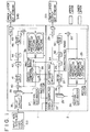
- FIG. 1 An encoding system or encoder according to the present invention will be described with reference to FIG. 1. First, a lower layer encoder block 2 will be described.
- processing is performed in units of a macro block.
- An input video signal S21 of a high resolution having a non-interlace structure is inputted to a down sampling circuit 22, in which it is converted into an interlace image of a low resolution.
- a motion vector from a motion estimator 37 is referred to to adaptively determine whether or not the input video signal S21 should be passed through a low-pass filter upon sampling of the data.
- the motion vector may be supplied from a motion estimator 24 which will be hereinafter described. In this instance, however, since a motion vector of an image a little prior in time is used, the encoding efficiency on the upper layer side sometimes exhibits a rather low level. Details of the down sampling circuit 22 will be hereinafter described.
- An interlace picture of a block format sampled by down sampling by the down sampling circuit 22 is stored into a frame memory set 23 and used for detection of a motion vector by the motion estimator 24.
- the motion estimator 24 detects a motion vector from a reference picture at present using a forward predictive picture and a backward predictive picture from among pictures stored in the frame memory set 23.
- detection of a motion vector one of motion vectors with which the absolute value sum of differences between fields or frames in units of a block is determined as a motion vector.
- a motion compensation frame memory set 25 in which selection of a macro block type is formed. Then, a predictive picture corresponding to the thus selected macro block type is sent to a difference unit 26.
- the difference unit 26 calculates a difference between the input picture and the predictive picture and outputs the difference to a discrete cosine transform (DCT) circuit 27.
- DCT discrete cosine transform
- the DCT circuit 27 transforms the input picture data or the difference data in units of a block by discrete cosine transform making use of a two-dimensional correlation of a video signal and outputs transform data obtained by the discrete cosine transform to a quantization circuit 28.
- the quantization circuit 28 quantizes the DCT transform data with a quantization step size, which is determined for each macro block or slice, and supplies quantization data obtained at an output terminal thereof as a result of the quantization to a variable length coding (VLC) circuit 29 and a dequantization circuit 30.
- VLC variable length coding
- the VLC circuit 29 processes the quantization data by variable length coding processing together with the quantization scale, the macro block type, the motion vector and so forth and outputs a lower layer bit stream S31 obtained by the variable length coding as transmission data.
- the dequantization circuit 30 dequantizes the quantization data sent out from the quantization circuit 28 into dequantization data and decodes the transform data of the output data before the transformation by the quantization circuit. Then, the dequantization circuit 30 supplies the dequantization data to an inverse discrete cosine transform (IDCT) circuit 32.
- IDCT inverse discrete cosine transform
- the IDCT circuit 32 transforms the dequantization data decoded by the dequantization circuit 30 back into decoded picture data by inverse transform processing to that of the DCT circuit and outputs the decoded picture data to the motion compensation frame memory set 25.
- the motion compensation frame memory set 25 performs motion compensation based on the motion vector supplied thereto from the motion estimator 24 and writes the decoded picture as a forward predictive picture or a backward predictive picture into the frame memories.
- the difference from the predictive picture is transmitted as an output of the IDCT circuit 32 to the motion compensation frame memory set 25, and accordingly, local decoding is performed by adding the difference to the predictive picture using an adder 33.
- the predictive picture here is identical with the picture decoded by the lower layer decoder, and forward, backward or bidirectional prediction is performed for a picture for next processing based on the predictive picture.
- the locally decoded picture outputted from the adder 33 is supplied also to an up sampling circuit 34. While the locally decoded picture of the lower layer has an interlace structure, interpolation is performed for the locally decoded picture by the up sampling circuit 34 so that the locally decoded picture is converted into a non-interlace picture similarly to that of the upper layer, and the non-interlace picture is inputted to a spatio-temporal predictor 39 of the upper layer.
- the up sampling circuit 34 adaptively refers to both of a picture from the upper layer which includes same spatial sample points with a full degree of accuracy but are different in temporal sample points and another picture from the lower layer which has a lower resolution due to sampling but has same temporal sampling points based on the motion information to produce a non-interlace interpolation picture. Details of the up sampling circuit 34 will be hereinafter described.
- the construction of the upper layer will be described.
- the input non-interlace video signal S21 is processed while remaining in the full degree of accuracy.
- the input non-interlace video signal S21 is delayed by a delay circuit 35 and then stored into a frame memory 36, whereafter detection of a motion vector is performed for the input non-interlace video signal S21 by a motion estimator 37.
- the motion estimator 37 operates similarly to the motion estimator 34.
- the information of the motion vector is sent to a motion compensation frame memory set 38, and a corresponding predictive picture is inputted to a spatio-temporal predictor 39.
- the spatio-temporal predictor 39 adaptively selects, by weighting, the predictive picture from the motion compensation frame memory set 38, that is, a predictive picture from the temporal direction, and the predictive picture from the up sampling circuit 34, that is, another predictive picture from the spatial direction.
- the spatio-temporal predictor 39 determines a coefficient ⁇ based on the motion information from the motion estimator 37, applies weighting of 1 - ⁇ to the predictive picture in the temporal direction, that is, the predictive picture of the upper layer and applies weighting of ⁇ to the predictive picture in the spatial direction, that is, the predictive picture from the lower layer, and then sends the thus weighted predictive pictures to a cumulative difference unit 40.
- the difference unit 40 calculates a difference between the input picture and the predictive pictures and outputs the difference to a discrete cosine transform circuit (DCT) 41.
- DCT discrete cosine transform circuit
- the DCT circuit 41 transforms the input picture data or the difference data by discrete cosine transform making use of a two-dimensional correction of a video signal and outputs transform data obtained by the discrete cosine transform to a quantization circuit 42.
- the quantization circuit 42 quantizes the DCT transform data with a quantization step size, which is determined for each macro block or slice, and supplies quantization data obtained at an output terminal thereof as a result of the quantization to a variable length coding (VLC) circuit 43 and a dequantization circuit 44.
- VLC variable length coding
- the VLC circuit 43 processes the quantization data by variable length coding processing together with the quantization scale, the macro block type, the motion vector and so forth and outputs an upper layer bit stream S45 obtained by the variable length coding as transmission data.
- the dequantization circuit 44 dequantizes the quantization data sent out from the quantization circuit 42 into a representative value to obtain dequantization data and decodes the transform data back of the output data before the transformation by the quantization circuit 42. Then, the dequantization circuit 44 supplies the dequantization data to an inverse discrete cosine transform (IDCT) circuit 46.
- IDCT inverse discrete cosine transform
- the IDCT circuit 46 transforms the dequantization data decoded by the dequantization circuit 44 back into decoded picture data by inverse transform processing to that of the DCT circuit 41 and outputs the decoded picture data to the motion compensation frame memory set 38.
- the motion compensation frame memory set 38 performs local decoding based on the motion vector supplied thereto from the motion estimator 37, the macro block type and the motion vector, and writes the locally decoded picture as a forward predictive picture or a backward predictive picture into the frame memories.
- the difference from the predictive picture is transmitted as an output of the IDCT circuit 46 to the motion compensation frame memory set 38, and accordingly, local decoding is performed by adding the difference to the predictive picture using an adder 47.
- the predictive picture here is identical with the picture decoded by the upper layer decoder, and forward or bidirectional prediction is performed for a picture for next processing based on the predictive picture.
- FIG. 3 shows the construction of the down sampling circuit 22.
- An input picture is inputted to a low-pass filter 71, and a switch 73 adaptively selects the input picture or the output picture of the low-pass filter 71 in response to a motion vector.
- the output of the switch 73 is alternately sampled by a sampling circuit 72. Since the picture after such sampling includes reflected components, normally it is acted upon uniformly by the low-pass filter 71, but due to the characteristic that the input is a non-interlace video signal, when the motion is small, sample points which are identical in spatial positions with but different in temporal positions from thinned out points are present without fail.
- FIG. 4 illustrates operation of the down sampling circuit 22.
- two columns of dots respectively indicate the positions of pixels arranged in the vertical direction in a single picture.
- the down sampling circuit 22 thins out those pixels at alternate positions from two pictures while sampling only those pixels surrounded by squares in FIG. 4 to convert the input non-interlace video signal into an interlace picture.
- the two points surrounded by a dotted line in FIG. 4 represent identical data, and accordingly, filtering processing is unnecessary as described above.
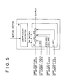
- FIG. 5 shows the construction of the up sampling circuit 34.
- the input to the up sampling circuit 34 includes data of the upper layer which are at the same spatial positions but are at different temporal positions, data interpolated from sample points of the same field of the lower layer, and data at the corresponding points from a different field of the lower layer. Weighting interpolation is thus performed for the inputs using coefficients w1, w2 and w3 which are adaptively determined by a coefficient generator 81.
- FIG. 6 illustrates operation of the up sampling circuit 34.
- two left side columns of dots respectively indicate the positions of pixels arranged in a vertical direction in a single picture of the upper layer.
- the other two right side columns of dots respectively indicate the positions of pixels arranged in a vertical direction in a single picture of the lower layer.
- the up sampling circuit 34 performs, for a pixel for which interpolation should be performed, interpolation from adjacent pixels in the same field of the lower layer and weighting interpolation from a pixel of the other field of the lower layer and another pixel at the same spatial position of the upper layer using the coefficients of w1 and w2, respectively.
- the up sampling circuit 34 adds the interpolation values obtained using the coefficients of w1 and w2 and the value at the same position of the lower layer, that is, the value of the point for which interpolation should be performed, with the weight of the coefficient of w3. For example, when the pixel for which interpolation should be performed is at the position of 205, the up sampling circuit 34 performs interpolation from the adjacent pixels 201 and 202 in the same field of the lower layer and weighted interpolation from the pixel 203 at the same position in the other field of the lower layer and the pixel 204 at the same spatial position of the upper layer using the coefficients of w1 and w2.
- the pixel 205 at the same position of the lower layer referred to with the coefficient of 1 - w3 is a point for which interpolation of zero has been performed, and since the value is 0, it does not have an influence upon the interpolation.
- the pixel for which interpolation should be performed is at the position of 206, that is, when the pixel 206 of the lower layer which is not equal to zero is present at the same position for which interpolation should be performed, since the points referred to with the coefficients of 1 - w1 and 1 - w2 are points for which interpolation of zero has been performed, they have no influence upon the interpolation.
- the down sampling circuit 22 and the up sampling circuit 34 can be adapted to conversion of a resolution at some other ratio than sampling or interpolation of 2:1 by suitably selecting an interpolation filter and sample points.
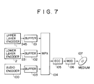
- FIG. 7 shows an example of a recording apparatus for a lower layer bit stream and an upper layer bit stream.
- an upper layer bit stream S45 outputted from the upper layer encoder 1 and a lower layer bit stream S31 outputted from the lower layer encoder 2 are multiplexed, after passing buffers 101 and 102, respectively, by a multiplexing circuit 104 with an audio signal, which has been encoded by an audio encoder 100 and passed through a buffer 103, and a synchronizing signal not shown.
- a multiplexed bit stream outputted from the multiplexing circuit 104 is processed by addition processing of a code for error correction by an error correction code addition circuit 105, and then processed by predetermined modulation by a modulator 106, whereafter it is recorded as concave and convex pits on a master disk 107 by means of a laser beam.
- a stamper is formed making use of the master disk 107, and a large number of copy disks, such as, for example, optical disks, are formed using the stamper.
- a lower layer bit stream S51 is inputted to the decoder of the lower layer by way of a transmission medium such as an optical disk.
- the bit stream S51 is inputted to a variable length decoding (IVLC) circuit 52.
- the variable length decoding circuit 52 decodes the bit stream S51 and outputs quantization data, a motion vector, a macro block type, a predictive mode, a quantization scale and so forth.
- a dequantization circuit 53 dequantizes the quantization data outputted from the variable length decoding circuit 52 into a representative value based on the quantization scale to obtain dequantization data and decodes the transform data before the transformation by the quantization circuit of the encoder. Then, the dequantization circuit 53 supplies the dequantization data to an inverse discrete cosine transform (IDCT) circuit 54.
- IDCT inverse discrete cosine transform
- the IDCT circuit 54 transforms the dequantization data decoded by the dequantization circuit 53 back into decoded picture data by inverse transform processing to that of the DCT circuit 27 and outputs the decoded picture data to a motion compensation frame memory set 55. Further, the decoded picture data having an interlace structure is simultaneously outputted as a lower layer output to an up sampling circuit 57.
- the motion compensation frame memory set 55 performs decoding based on the output data of the IDCT circuit 54, the macroblock type and the motion vector and writes the decoded picture as a forward predictive picture or a backward predictive picture into the frame memories.
- a difference from a predictive picture is transmitted as the output of the IDCT circuit 54 to the motion compensation frame memory set 55, and accordingly, decoding is performed by adding the difference to the predictive picture using an adder 56 to form a lower layer picture S66 having an interlace structure as a decoded picture.
- the predictive picture here is identical with the picture decoded by the local decoder of the encoder, and forward, backward or bidirectional prediction is performed for a picture for next processing based on the predictive picture.
- the output picture S66 of the lower layer is inputted to the up sampling circuit 57, in which it is processed by interpolation so that it is converted into a non-interlace picture.
- the non-interlace picture is inputted to a spatio-temporal predictor 58.
- the up sampling circuit 57 operates similarly to the up sampling circuit 34 described hereinabove in connection with the encoder.
- An upper layer input bit stream 59 is inputted to the upper layer.
- the bit stream 59 is inputted to a variable length decoding (IVLC) circuit 60.
- the variable length decoding circuit 60 decodes the bit stream 59 and outputs quantization data, a motion vector, a macroblock type and a quantization scale.
- a dequantization circuit 61 dequantizes the quantization data outputted from the variable length decoding circuit 60 into a representative value based on the quantization scale to obtain dequantization data and decodes the transform data before the transformation by the quantization circuit of the encoder. Then, the dequantization circuit 61 supplies the dequantization data to an inverse discrete cosine transform (IDCT) circuit 62.
- IDCT inverse discrete cosine transform
- the IDCT circuit 62 transforms the dequantization data decoded by the dequantization circuit 61 back into decoded picture data by inverse transform processing to that of the DCT circuit 41 and outputs the decoded picture data to a motion compensation frame memory set 63. Further, the decoded picture data having an interlace structure is simultaneously outputted as an upper layer output picture S65 having a non-interlace structure.
- the motion compensation frame memory set 63 performs decoding based on the output data of the IDCT circuit 62, the macro block type and the motion vector and writes the decoded picture as a forward predictive picture or a backward predictive picture into the frame memories.
- the picture corresponding to the selected macro block type is inputted to the spatio-temporal predictor 58.
- the spatio-temporal predictor 58 operates similarly to the spatio-temporal predictor 39 of FIG. 1 in the encoder described hereinabove.
- a picture obtained by adaptively weighting a predictive picture of the upper layer which has a spatially high resolution but is different in temporal sample points and another predictive picture of the lower layer which may possibly be inferior in spatial resolution but is same in temporal sample points is outputted from the spatio-temporal predictor 58.
- decoding is performed by adding the difference to the predictive picture using an adder 64.
- both of the output of a non-interlace picture and the output of an interlace picture can be obtained from an upper layer input bit stream and a lower layer output bit stream.
- bit stream outputted from the encoder is recorded onto an optical disk, it may otherwise be sent out into a transmission line for the ISDN or the communications by satellites.
Landscapes
- Engineering & Computer Science (AREA)
- Multimedia (AREA)
- Signal Processing (AREA)
- Compression Or Coding Systems Of Tv Signals (AREA)
- Compression, Expansion, Code Conversion, And Decoders (AREA)
- Image Processing (AREA)
- Television Systems (AREA)
Claims (14)
- Appareil de codage de signal vidéo, comprenant :caractérisé en ce que :un moyen de sous-échantillonnage (22) servant à échantillonner un signal vidéo d'entrée non entrelacé par sous-échantillonnage afin de former un signal d'image entrelacé ;un premier moyen de codage (23-33) servant à coder le signal d'image entrelacé afin de former un premier train de bits ;un moyen de sur-échantillonnage (34) servant à échantillonner le signal vidéo sur la base du premier train de bits par sur-échantillonnage afin de former un signal d'image non entrelacé ; etun deuxième moyen de codage (35-47) servant à coder le signal d'image d'entrée non entrelacé à l'aide du signal d'image non entrelacé venant du moyen de sur-échantillonnage afin de former un deuxième train de bits, où le premier moyen de codage (23-33) comporte un premier moyen de conversion (26, 27, 28) servant à effectuer une conversion prédéterminée du signal d'image entrelacé, et un premier moyen de décodage local (30, 32, 33) servant à décoder localement le signal de sortie dudit premier moyen de conversion (26, 27, 28) afin de former un premier signal d'image localement décodé, ledit moyen de sur-échantillonnage (34) échantillonnant le premier signal d'image localement décodé par sur-échantillonnage afin de former le signal d'image non entrelacé,
le deuxième moyen de codage (35-47) comporte un deuxième moyen de conversion (40, 41, 42) servant à effectuer une conversion prédéterminée du signal d'entrée non entrelacé, un deuxième moyen de décodage local (44, 46, 47) servant à décoder localement le signal de sortie dudit deuxième moyen de conversion (40, 41, 42) afin de former un deuxième signal d'image localement décodé, un moyen de compensation de mouvement (38) servant à appliquer une compensation de mouvement au deuxième signal d'image localement décodé afin de former un premier signal d'image prédictif, et un moyen (39) de formation de signal d'image prédictif servant à former un deuxième signal d'image prédictif sur la base du signal d'image non entrelacé qui est délivré par ledit moyen de sur-échantillonnage (34) et du premier signal d'image prédictif. - Appareil de codage de signal vidéo selon la revendication 1, caractérisé en ce que ledit moyen de sous-échantillonnage (22) comporte un moyen d'éclaircissement servant à éliminer par éclaircissement des pixels du signal vidéo d'entrée non entrelacé, et un moyen de filtrage assurant une commutation entre l'existence et l'absence d'un filtrage sur le signal d'entrée dudit moyen d'éclaircissement en réponse à l'information de mouvement.
- Appareil de codage de signal vidéo selon la revendication 1 ou 2, caractérisé en ce que ledit moyen de sur-échantillonnage (34) comporte un moyen d'interpolation servant à effectuer une interpolation sur la base de pixels du premier signal d'image prédictif se trouvant aux mêmes positions et, ou bien, de pixels du premier signal d'image localement décodé se trouvant aux mêmes positions d'une trame adjacente.
- Appareil de codage de signal vidéo selon la revendication 3, caractérisé en ce que ledit moyen d'interpolation comporte un moyen générateur de coefficients (81) servant à produire un coefficient prédéterminé en réponse à l'information de mouvement.
- Appareil de décodage de signal vidéo, comprenant :un premier moyen de décodage (52-56) servant à former un signal d'image décodé entrelacé à partir d'un premier train de bits d'entrée ;un moyen de sur-échantillonnage (57) servant à échantillonner le signal d'image décodé entrelacé par sur-échantillonnage afin de former un premier signal décodé non entrelacé ;un deuxième moyen de décodage (60-64) servant à former un deuxième signal d'image décodé non entrelacé à partir d'un deuxième train de bits ;un moyen de compensation de mouvement (63) servant à appliquer une compensation de mouvement au deuxième signal d'image décodé non entrelacé afin de former un premier signal d'image prédictif ; etun moyen (58) de formation d'image prédictif servant à former un deuxième signal d'image prédictif afin de décoder le deuxième signal d'image décodé non entrelacé sur la base du premier signal d'image décodé non entrelacé et du premier signal d'image prédictif.
- Appareil de décodage de signal vidéo selon la revendication 5, caractérisé en ce que ledit moyen de sur-échantillonnage (57) comporte un moyen d'interpolation servant à effectuer une interpolation sur la base de pixels du premier signal d'image prédictif se trouvant aux mêmes positions et, ou bien, de pixels du signal d'image décodé entrelacé se trouvant aux mêmes positions d'une trame adjacente.
- Appareil de décodage de signal vidéo selon la revendication 6, caractérisé en ce que ledit moyen d'interpolation comporte un moyen générateur de coefficients (81) servant à produire un coefficient prédéterminé sur la base de l'information de mouvement.
- Procédé de codage de signal vidéo, comprenant les opérations suivantes :caractérisé en ce que :échantillonner un signal vidéo d'entrée non entrelacé par sous-échantillonnage afin de former un signal d'image entrelacé ;coder le signal d'image entrelacé afin de former un premier train de bits ;échantillonner un signal sur la base du premier train de bits par sur-échantillonnage afin de former un signal d'image non entrelacé ; etcoder le signal d'image d'entrée non entrelacé à l'aide du signal d'image non entrelacé formé par ledit sur-échantillonnage afin de former un deuxième train de bits,où l'opération de codage du signal d'image entrelacé comporte les opérations consistant à appliquer une conversion prédéterminée au signal d'image entrelacé afin de former des premières données de coefficient et décoder localement les données de coefficient afin de former un premier signal d'image localement décodé, le premier signal d'image localement décodé étant sur-échantillonné afin de former le signal d'image non entrelacé,
l'opération de codage du signal d'image d'entrée non entrelacé comporte les opérations suivantes : appliquer une conversion prédéterminée au signal d'image d'entrée non entrelacé afin de former des deuxièmes données de coefficient, décoder localement les deuxièmes données de coefficient afin de former un deuxième signal d'image localement décodé, appliquer une compensation de mouvement au deuxième signal d'image localement décodé afin de former un premier signal d'image prédictif, et former un deuxième signal d'image prédictif sur la base du premier signal d'image localement décodé et du premier signal d'image prédictif. - Procédé de codage de signal vidéo selon la revendication 8, caractérisé en ce que, lors du sous-échantillonnage, on fait commuter l'existence ou l'absence de filtrage en réponse à la compensation de mouvement.
- Procédé de codage de signal vidéo selon la revendication 8 ou 9, caractérisé en ce que, lors du sur-échantillonnage, on effectue une interpolation sur la base de pixels du premier signal d'image prédictif se trouvant aux mêmes positions et, ou bien, de pixels du premier signal d'image localement décodé se trouvant aux mêmes positions d'une trame adjacente.
- Procédé de codage de signal vidéo selon la revendication 10, caractérisé en ce que l'opération d'interpolation comporte les opérations suivantes : appliquer une pondération prédéterminée aux pixels du premier signal d'image prédictif se trouvant aux mêmes positions et, ou bien, aux pixels du premier signal d'image localement décodé se trouvant aux mêmes positions d'une trame adjacente, en réponse à l'information de mouvement.
- Procédé de décodage de signal vidéo, comprenant les opérations suivantes :former un signal d'image décodé entrelacé à partir d'un premier train de bits ;échantillonner le signal d'image décodé entrelacé par sur-échantillonnage afin de former un premier signal d'image décodé non entrelacé ;former un deuxième signal d'image décodé non entrelacé à partir d'un deuxième train de bits ;appliquer une compensation de mouvement au deuxième signal d'image décodé non entrelacé afin de former un premier signal d'image prédictif ; etformer un deuxième signal d'image prédictif afin de décoder le deuxième signal d'image décodé non entrelacé sur la base du premier signal d'image décodé entrelacé et du premier signal d'image prédictif.
- Procédé de décodage de signal vidéo selon la revendication 12, caractérisé en ce que, lors du sur-échantillonnage, on effectue une interpolation sur la base de pixels du premier signal d'image prédictif se trouvant aux mêmes positions et, ou bien, de pixels du signal d'image décodé entrelacé se trouvant aux mêmes positions d'une trame adjacente.
- Procédé de décodage de signal vidéo selon la revendication 13, caractérisé en ce que l'opération d'interpolation comporte les opérations suivantes : appliquer une pondération prédéterminée aux pixels du premier signal d'image prédictif se trouvant aux mêmes positions et, ou bien, aux pixels du premier signal d'image localement décodé se trouvant aux mêmes positions d'une trame adjacente.
Applications Claiming Priority (2)
| Application Number | Priority Date | Filing Date | Title |
|---|---|---|---|
| JP29420492A JP3545000B2 (ja) | 1992-11-02 | 1992-11-02 | 画像信号符号化装置、画像信号復号化装置 |
| JP294204/92 | 1992-11-02 |
Publications (3)
| Publication Number | Publication Date |
|---|---|
| EP0596423A2 EP0596423A2 (fr) | 1994-05-11 |
| EP0596423A3 EP0596423A3 (en) | 1994-09-28 |
| EP0596423B1 true EP0596423B1 (fr) | 1999-02-24 |
Family
ID=17804673
Family Applications (1)
| Application Number | Title | Priority Date | Filing Date |
|---|---|---|---|
| EP19930117577 Expired - Lifetime EP0596423B1 (fr) | 1992-11-02 | 1993-10-29 | Appareil de codage/décodage à couches pour signaux vidéo d'entrée non-entrelacés |
Country Status (7)
| Country | Link |
|---|---|
| US (1) | US5475435A (fr) |
| EP (1) | EP0596423B1 (fr) |
| JP (1) | JP3545000B2 (fr) |
| KR (1) | KR940013224A (fr) |
| CN (1) | CN1048612C (fr) |
| DE (1) | DE69323586T2 (fr) |
| TW (1) | TW325944U (fr) |
Families Citing this family (48)
| Publication number | Priority date | Publication date | Assignee | Title |
|---|---|---|---|---|
| CA2126467A1 (fr) * | 1993-07-13 | 1995-01-14 | Barin Geoffry Haskell | Codage et decodage variables pour systeme video haute definition progressif |
| CA2127151A1 (fr) * | 1993-09-21 | 1995-03-22 | Atul Puri | Codage et decodage video a gradation spatiale |
| DE4416967A1 (de) * | 1994-05-13 | 1995-11-16 | Thomson Brandt Gmbh | Verfahren und Vorrichtung zur Transcodierung von Bitströmen mit Videodaten |
| EP1411734B1 (fr) * | 1994-06-24 | 2005-05-11 | Mitsubishi Denki Kabushiki Kaisha | Disque optique et méthode de reproduction |
| EP1282317B1 (fr) * | 1994-06-24 | 2004-04-07 | Mitsubishi Denki Kabushiki Kaisha | Disque optique et méthode de reproduction |
| US5809201A (en) | 1994-06-24 | 1998-09-15 | Mitsubishi Denki Kabushiki Kaisha | Specially formatted optical disk and method of playback |
| US5644361A (en) * | 1994-11-30 | 1997-07-01 | National Semiconductor Corporation | Subsampled frame storage technique for reduced memory size |
| DE69619002T2 (de) * | 1995-03-10 | 2002-11-21 | Kabushiki Kaisha Toshiba, Kawasaki | Bildkodierungs-/-dekodierungsvorrichtung |
| US6957350B1 (en) | 1996-01-30 | 2005-10-18 | Dolby Laboratories Licensing Corporation | Encrypted and watermarked temporal and resolution layering in advanced television |
| US6259738B1 (en) * | 1996-10-31 | 2001-07-10 | Kabushiki Kaisha Toshiba | Video encoding apparatus and video decoding apparatus |
| JP4034380B2 (ja) * | 1996-10-31 | 2008-01-16 | 株式会社東芝 | 画像符号化/復号化方法及び装置 |
| WO1998025407A1 (fr) * | 1996-12-06 | 1998-06-11 | Matsushita Electric Industrial Co., Ltd. | Procede et appareil de transmission, codage et decodage de signaux video, et d'entegistrement/lecture de disque optique |
| JP3763172B2 (ja) * | 1996-12-16 | 2006-04-05 | ソニー株式会社 | ディジタル信号復号方法及び装置、並びにディジタル信号再生装置 |
| US6057884A (en) * | 1997-06-05 | 2000-05-02 | General Instrument Corporation | Temporal and spatial scaleable coding for video object planes |
| JP3844844B2 (ja) * | 1997-06-06 | 2006-11-15 | 富士通株式会社 | 動画像符号化装置及び動画像符号化方法 |
| KR100482282B1 (ko) * | 1997-07-03 | 2005-07-11 | 주식회사 팬택앤큐리텔 | 신축형(스케일러블)부호화시고위계층(EnhancementLayer)부호화방법 |
| US6477202B1 (en) * | 1997-09-03 | 2002-11-05 | Matsushita Electric Industrial Co., Ltd. | Apparatus of layered picture coding, apparatus of picture decoding, methods of picture decoding, apparatus of recording for digital broadcasting signal, and apparatus of picture and audio decoding |
| US6014182A (en) | 1997-10-10 | 2000-01-11 | Faroudja Laboratories, Inc. | Film source video detection |
| US6108041A (en) * | 1997-10-10 | 2000-08-22 | Faroudja Laboratories, Inc. | High-definition television signal processing for transmitting and receiving a television signal in a manner compatible with the present system |
| JP3164056B2 (ja) * | 1998-03-19 | 2001-05-08 | 日本ビクター株式会社 | 動画像符号化復号化装置、動画像符号化復号化方法及び動画像符号記録媒体 |
| KR100335105B1 (ko) * | 1998-12-23 | 2002-05-04 | 구자홍 | 영상의 부호화 및 복호화 방법 |
| JP2001203988A (ja) | 2000-01-21 | 2001-07-27 | Nec Corp | 画像復号装置、半導体装置、及び画像復号方法 |
| JP2002010251A (ja) * | 2000-06-19 | 2002-01-11 | Matsushita Electric Ind Co Ltd | 映像信号符号化装置および映像信号復号化装置 |
| US20020126759A1 (en) | 2001-01-10 | 2002-09-12 | Wen-Hsiao Peng | Method and apparatus for providing prediction mode fine granularity scalability |
| US8374237B2 (en) | 2001-03-02 | 2013-02-12 | Dolby Laboratories Licensing Corporation | High precision encoding and decoding of video images |
| US7266150B2 (en) | 2001-07-11 | 2007-09-04 | Dolby Laboratories, Inc. | Interpolation of video compression frames |
| US6816552B2 (en) * | 2001-07-11 | 2004-11-09 | Dolby Laboratories Licensing Corporation | Interpolation of video compression frames |
| US8111754B1 (en) | 2001-07-11 | 2012-02-07 | Dolby Laboratories Licensing Corporation | Interpolation of video compression frames |
| US20030112863A1 (en) | 2001-07-12 | 2003-06-19 | Demos Gary A. | Method and system for improving compressed image chroma information |
| EP1442601A1 (fr) * | 2001-10-26 | 2004-08-04 | Koninklijke Philips Electronics N.V. | Procede et dispositif pour la compression a echelonnabilite spatiale |
| JP2005506816A (ja) * | 2001-10-26 | 2005-03-03 | コーニンクレッカ フィリップス エレクトロニクス エヌ ヴィ | 適応的コンテンツフィルタリングを用いた空間拡張可能圧縮の機構 |
| JP2005531959A (ja) * | 2002-06-28 | 2005-10-20 | コーニンクレッカ フィリップス エレクトロニクス エヌ ヴィ | 空間スケーラブル圧縮方法及び装置 |
| US7266247B2 (en) | 2002-09-30 | 2007-09-04 | Samsung Electronics Co., Ltd. | Image coding method and apparatus using spatial predictive coding of chrominance and image decoding method and apparatus |
| EP1455534A1 (fr) * | 2003-03-03 | 2004-09-08 | Thomson Licensing S.A. | Codage et décodage échelonnables pour des signaux vidéo numériques entrelacés |
| EP1621021A1 (fr) * | 2003-04-29 | 2006-02-01 | Koninklijke Philips Electronics N.V. | Appareil de traitement d'images |
| JP2007532046A (ja) * | 2003-12-22 | 2007-11-08 | コーニンクレッカ フィリップス エレクトロニクス エヌ ヴィ | 互換的インターレースsdtvとプログレッシブhdtv |
| KR100667806B1 (ko) * | 2005-07-07 | 2007-01-12 | 삼성전자주식회사 | 영상 부호화 및 복호화 방법 및 장치 |
| JP5017825B2 (ja) * | 2005-09-15 | 2012-09-05 | ソニー株式会社 | 復号装置および復号方法 |
| US8457201B2 (en) * | 2006-01-09 | 2013-06-04 | Lg Electronics Inc. | Inter-layer prediction method for video signal |
| US8315308B2 (en) * | 2006-01-11 | 2012-11-20 | Qualcomm Incorporated | Video coding with fine granularity spatial scalability |
| US7817184B1 (en) | 2006-03-15 | 2010-10-19 | The Directv Group, Inc. | Methods and apparatus to test receivers |
| DE102006032021A1 (de) * | 2006-07-10 | 2008-01-17 | Nokia Siemens Networks Gmbh & Co.Kg | Verfahren und Enkodiervorrichtung zum Kodieren eines Bildbereiches eines Bildes einer Bildsequenz in zumindest zwei Qualitätsstufen, sowie Verfahren und Dekodiervorrichtung zum De-kodieren eines ersten kodierten Datenstroms und eines zweiten kodierten Datenstroms |
| CN101287119B (zh) * | 2008-04-28 | 2010-06-02 | 北京大学深圳研究生院 | 基于频谱的图像分层编解码方法及系统 |
| CN102113326A (zh) | 2008-08-04 | 2011-06-29 | 杜比实验室特许公司 | 重叠块差异估计和补偿体系结构 |
| JP5416277B2 (ja) * | 2009-07-10 | 2014-02-12 | サムスン エレクトロニクス カンパニー リミテッド | 階層的映像符号化における空間予測方法及び装置 |
| US9049445B2 (en) | 2012-01-04 | 2015-06-02 | Dolby Laboratories Licensing Corporation | Dual-layer backwards-compatible progressive video delivery |
| EA201492099A1 (ru) * | 2012-05-14 | 2015-04-30 | Лука Россато | Разложение остаточных данных при кодировании, декодировании и реконструкции сигнала в многоуровневой иерархии |
| JP2016005032A (ja) | 2014-06-13 | 2016-01-12 | ソニー株式会社 | 符号化装置、符号化方法、カメラ、レコーダおよびカメラ一体型レコーダ |
Family Cites Families (3)
| Publication number | Priority date | Publication date | Assignee | Title |
|---|---|---|---|---|
| US5128791A (en) * | 1990-08-13 | 1992-07-07 | Bell Communications Research, Inc. | Multi-channel HDTV system |
| JPH04177992A (ja) * | 1990-11-09 | 1992-06-25 | Victor Co Of Japan Ltd | 階層性を有する画像符号化装置 |
| US5353119A (en) * | 1990-11-15 | 1994-10-04 | Sony United Kingdom Limited | Format conversion of digital video signals, integration of digital video signals into photographic film material and the like, associated signal processing, and motion compensated interpolation of images |
-
1992
- 1992-11-02 JP JP29420492A patent/JP3545000B2/ja not_active Expired - Lifetime
-
1993
- 1993-10-27 TW TW085218477U patent/TW325944U/zh unknown
- 1993-10-28 US US08/145,325 patent/US5475435A/en not_active Expired - Lifetime
- 1993-10-29 DE DE69323586T patent/DE69323586T2/de not_active Expired - Lifetime
- 1993-10-29 EP EP19930117577 patent/EP0596423B1/fr not_active Expired - Lifetime
- 1993-11-02 KR KR1019930023308A patent/KR940013224A/ko not_active Ceased
- 1993-11-02 CN CN93114263A patent/CN1048612C/zh not_active Expired - Lifetime
Also Published As
| Publication number | Publication date |
|---|---|
| EP0596423A2 (fr) | 1994-05-11 |
| US5475435A (en) | 1995-12-12 |
| JP3545000B2 (ja) | 2004-07-21 |
| KR940013224A (ko) | 1994-06-25 |
| CN1090116A (zh) | 1994-07-27 |
| DE69323586T2 (de) | 1999-06-24 |
| CN1048612C (zh) | 2000-01-19 |
| JPH06153183A (ja) | 1994-05-31 |
| DE69323586D1 (de) | 1999-04-01 |
| TW325944U (en) | 1998-01-21 |
| EP0596423A3 (en) | 1994-09-28 |
Similar Documents
| Publication | Publication Date | Title |
|---|---|---|
| EP0596423B1 (fr) | Appareil de codage/décodage à couches pour signaux vidéo d'entrée non-entrelacés | |
| JP3381855B2 (ja) | 画像信号符号化方法および画像信号符号化装置、並びに画像信号復号化方法および画像信号復号化装置 | |
| EP0782342B1 (fr) | Système et méthodes de codage et décodage vidéo | |
| US6173013B1 (en) | Method and apparatus for encoding enhancement and base layer image signals using a predicted image signal | |
| KR100311294B1 (ko) | 화상신호부호화방법및화상신호부호화장치및화상신호복호화방법및화상신호복호화장치 | |
| JPH09224254A (ja) | 動き推定のための装置および方法 | |
| US5191414A (en) | Interfield predictive encoder and decoder for reproducing a signal subjected to predictive encoding by encoder into an image signal | |
| JPH07212761A (ja) | 階層符号化装置及び階層復号化装置 | |
| US6219103B1 (en) | Motion-compensated predictive coding with video format conversion | |
| US5905534A (en) | Picture decoding and encoding method and apparatus for controlling processing speeds | |
| JP2755851B2 (ja) | 動画像符号化装置及び動画像符号化方法 | |
| JPH0678294A (ja) | 符号化方法、符号化装置、および復号化装置 | |
| US6556714B2 (en) | Signal processing apparatus and method | |
| JP2000036963A (ja) | 画像符号化装置、画像符号化方法および画像復号化装置 | |
| EP0944264B1 (fr) | Appareil et procédé de codage/décodage d'images animées et milieu de stockage pour stocker les images animées codées | |
| JPH06205397A (ja) | 動画像符号化装置 | |
| JP3301375B2 (ja) | 画像信号符号化装置及び方法、画像信号復号装置及び方法 | |
| JP2883592B2 (ja) | 動画像復号化装置及び動画像復号化方法 | |
| Eisips et al. | Global motion estimation for image sequence coding applications | |
| JP2883585B2 (ja) | 動画像符号化装置及び動画像符号化方法 | |
| JP3186406B2 (ja) | 画像合成符号化方法及び画像合成装置 | |
| JP4210925B2 (ja) | 画像信号生成装置および方法、並びに、画像信号再生装置および方法 | |
| JP2758378B2 (ja) | 動画像復号化装置及び動画像復号化方法 | |
| JPH07107488A (ja) | 動画像符号化装置 | |
| JP2002077910A (ja) | 可変画像レート符号化装置、可変画像レート復号化装置、可変画像レート符号化方法、及び可変画像レート復号化方法 |
Legal Events
| Date | Code | Title | Description |
|---|---|---|---|
| PUAI | Public reference made under article 153(3) epc to a published international application that has entered the european phase |
Free format text: ORIGINAL CODE: 0009012 |
|
| AK | Designated contracting states |
Kind code of ref document: A2 Designated state(s): DE FR GB |
|
| PUAL | Search report despatched |
Free format text: ORIGINAL CODE: 0009013 |
|
| AK | Designated contracting states |
Kind code of ref document: A3 Designated state(s): DE FR GB |
|
| 17P | Request for examination filed |
Effective date: 19950306 |
|
| 17Q | First examination report despatched |
Effective date: 19970214 |
|
| GRAG | Despatch of communication of intention to grant |
Free format text: ORIGINAL CODE: EPIDOS AGRA |
|
| GRAG | Despatch of communication of intention to grant |
Free format text: ORIGINAL CODE: EPIDOS AGRA |
|
| GRAH | Despatch of communication of intention to grant a patent |
Free format text: ORIGINAL CODE: EPIDOS IGRA |
|
| GRAH | Despatch of communication of intention to grant a patent |
Free format text: ORIGINAL CODE: EPIDOS IGRA |
|
| GRAA | (expected) grant |
Free format text: ORIGINAL CODE: 0009210 |
|
| AK | Designated contracting states |
Kind code of ref document: B1 Designated state(s): DE FR GB |
|
| REF | Corresponds to: |
Ref document number: 69323586 Country of ref document: DE Date of ref document: 19990401 |
|
| ET | Fr: translation filed | ||
| PLBE | No opposition filed within time limit |
Free format text: ORIGINAL CODE: 0009261 |
|
| STAA | Information on the status of an ep patent application or granted ep patent |
Free format text: STATUS: NO OPPOSITION FILED WITHIN TIME LIMIT |
|
| 26N | No opposition filed | ||
| REG | Reference to a national code |
Ref country code: GB Ref legal event code: IF02 |
|
| REG | Reference to a national code |
Ref country code: GB Ref legal event code: 746 Effective date: 20120703 |
|
| REG | Reference to a national code |
Ref country code: DE Ref legal event code: R084 Ref document number: 69323586 Country of ref document: DE Effective date: 20120614 |
|
| PGFP | Annual fee paid to national office [announced via postgrant information from national office to epo] |
Ref country code: DE Payment date: 20121023 Year of fee payment: 20 Ref country code: FR Payment date: 20121031 Year of fee payment: 20 |
|
| PGFP | Annual fee paid to national office [announced via postgrant information from national office to epo] |
Ref country code: GB Payment date: 20121019 Year of fee payment: 20 |
|
| REG | Reference to a national code |
Ref country code: DE Ref legal event code: R071 Ref document number: 69323586 Country of ref document: DE |
|
| REG | Reference to a national code |
Ref country code: GB Ref legal event code: PE20 Expiry date: 20131028 |
|
| PG25 | Lapsed in a contracting state [announced via postgrant information from national office to epo] |
Ref country code: GB Free format text: LAPSE BECAUSE OF EXPIRATION OF PROTECTION Effective date: 20131028 Ref country code: DE Free format text: LAPSE BECAUSE OF EXPIRATION OF PROTECTION Effective date: 20131030 |