EP0597149A1 - Passerelle entre deux véhicules accouplés - Google Patents
Passerelle entre deux véhicules accouplés Download PDFInfo
- Publication number
- EP0597149A1 EP0597149A1 EP92121711A EP92121711A EP0597149A1 EP 0597149 A1 EP0597149 A1 EP 0597149A1 EP 92121711 A EP92121711 A EP 92121711A EP 92121711 A EP92121711 A EP 92121711A EP 0597149 A1 EP0597149 A1 EP 0597149A1
- Authority
- EP
- European Patent Office
- Prior art keywords
- transition according
- frame
- link bridge
- wall cladding
- ceiling
- Prior art date
- Legal status (The legal status is an assumption and is not a legal conclusion. Google has not performed a legal analysis and makes no representation as to the accuracy of the status listed.)
- Granted
Links
- 238000005253 cladding Methods 0.000 claims description 32
- 230000007704 transition Effects 0.000 claims description 26
- 239000007787 solid Substances 0.000 claims description 2
- 238000006073 displacement reaction Methods 0.000 description 3
- 239000000872 buffer Substances 0.000 description 2
- 239000004744 fabric Substances 0.000 description 2
Images


Classifications
-
- B—PERFORMING OPERATIONS; TRANSPORTING
- B61—RAILWAYS
- B61D—BODY DETAILS OR KINDS OF RAILWAY VEHICLES
- B61D17/00—Construction details of vehicle bodies
- B61D17/04—Construction details of vehicle bodies with bodies of metal; with composite, e.g. metal and wood body structures
- B61D17/20—Communication passages between coaches; Adaptation of coach ends therefor
Definitions
- the invention relates to a transition between two coupled vehicles, in particular with a diagonally displaceable link bridge, the link bridge being spanned by a bellows attached to the end faces of the vehicles.
- a transition of the type mentioned is known for example from EP-PS 03 31 121 or EP-OS 92 11 3553.9. With these transitions, the bellows is visible from the inside. It is known that the very expensive bellows are deliberately destroyed again and again by the passengers, for example by cutting them open with knives.
- an inner wall cladding consisting of solid elements, the inner wall cladding being pivotally connected to the articulated bridge in the direction of the vehicle longitudinal axis in order to give way to the travel movements which occur between two articulated vehicles to be able to.
- Such an interior wall cladding not only protects the bellows against vandalism, it also gives the passenger a positive aesthetic impression.
- the inner wall cladding comprises in particular two side wall parts, each of which is pivotally connected to the link bridge in the direction of the vehicle longitudinal axis.
- the side wall parts are connected to one another by ceiling elements forming a closed ceiling, the ceiling elements being connected diagonally displaceably to the side wall parts in accordance with the design of the link bridge. It follows that for the diagonal displacement of the ceiling, the individual ceiling elements are each horizontally pivotably connected to the wall parts.
- the interior wall cladding is designed to be movable relative to the vehicles due to the driving movements that occur, there is a circumferential gap between the interior wall cladding and the respective end face of the vehicle.
- the interior wall cladding is connected to the end face of the respective vehicle by an elastic closure, for example by a fabric sheet.
- both the side wall parts and the ceiling are held by a U-shaped frame which is pivotally connected to the link bridge.
- This frame serves as a support for both the side wall parts and for the ceiling; if both the side wall parts and the ceiling elements do not have to perform a supporting function, they can be designed more easily.
- the frame is constructed in several parts, in particular the vertical frame supports being pivoted horizontally and vertically by a joint, in particular by a double joint, to the horizontally running frame cross member are. This biaxial design of each joint in the manner of a universal joint prevents the inner wall cladding from becoming tense.
- the side wall parts are spaced apart from the link bridge, if necessary by tapering the lower edges of the side wall parts.
- Limiting means are provided to limit this pivoting movement of the inner wall cladding.
- the limiting means in this case comprise a bracket arranged on the vehicle above the ceiling of the inner wall cladding, the bracket interacting with a roller which is arranged on a vertical axis in the ceiling area.
- the vertical axis is arranged approximately in the middle of the horizontal frame cross member.
- the end face of the bracket hits the vertically arranged roller, the bracket sliding along the roller while cornering at the same time.
- each vehicle has such a bracket interacting with the roller.
- the inner wall cladding can be reset in its starting position by means of spring force after the swiveling movement.
- the U-shaped frame pivots together with the inner wall cladding attached to it.
- the swivel movement is then limited by stops.
- the vertical frame supports are mounted between two supports, which are preferably arranged in a V-shape with respect to one another, in order to limit this pivoting movement in the region of the mounting of the U-shaped frame;
- There is a spring between each strut and the vertical frame support so that the U-shaped frame as a whole strives to return to its original position.
- the attacks for example in Form of rubber buffers, are located in the springs, the buffers serving as holders for the stops.
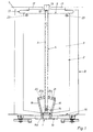
- the inner wall cladding of the transition denoted overall by 1 has the reference number 2.
- the transition is composed of the bellows 1 arranged at the front ends and the link bridge 1 b (FIG. 3).
- the inner wall cladding 2 consists of the two side wall parts 3, which are connected to one another by the ceiling denoted overall by 5.
- the ceiling designated 5 consists of individual ceiling elements 8, which are horizontally displaceably connected to the side wall parts 3 in accordance with the design of the link bridge.
- the side wall parts have an angle 11 (FIG. 2) on which the individual ceiling element 8 is rotatably supported by the axis 5a. Both the side wall parts 3 and the ceiling 5 are held by the U-shaped frame designated overall by 6.
- the frame 6 consists of the two vertical frame supports 7, which are connected to one another by the horizontal frame cross member 9 by means of the double joints 10.
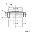
- the design of the double joint 10 results from FIG. 5.
- the vertical axis of the joint 10 is designated 10a and the horizontal axis 10b.
- the horizontal axis 10b carries the disc 10c, which is pivotable about the axis 10a.
- the horizontal frame crossmember 9 has the vertical axis 12 which receives the rollers 13 (FIG. 4).
- the frame supports 7 of the frame 6 are each pivotably mounted about the horizontal axis 14a by the bearing 14 arranged on the link bridge 1.
- the distance 15 between link bridge 1 and side wall part 3, which is covered by covers 16, also serves in particular to carry out the tilting movement (FIG. 1).
- brackets 17 are provided above the ceiling (FIG. 1 and FIG. 3), the bracket 17 being shown in FIG. 3 only on one side. If the vehicles are offset in height from one another, one of the brackets 17 abuts the roller 13, which initially limits the swivel path.
- this pivoting movement is superimposed parallel to the longitudinal axis of the vehicle with a horizontal displacement of the bracket relative to the rollers 13 due to cornering, the roller 13 slides along the end face of the bracket 17 (FIG. 4).
- Each vertical frame support 7 is located in the area of its bearing 14 between the two struts 18, 19 arranged in a V-shape relative to one another (FIG. 1). If the height offset between two adjacent vehicles is so great that the pivoting would go beyond the limit formed by the bracket 17 in connection with the roller 13, the vertical frame support 7 and thus the entire frame 6 pivots on one or the other strut 18 , 19 to. Finally, the struts 18, 19, in conjunction with the stops 20a, 21a carrying the springs 20, 21, form the limit for the pivoting movement of the inner wall cladding as a whole. After the height offset of the two vehicles has ended, the frame 6 and thus the entire inner wall cladding 2 are returned to their starting position due to the springs 20, 21.
- an elastic closure 22 is provided in the form of a circumferential fabric web.
- lateral stops 23 are provided.
Landscapes
- Engineering & Computer Science (AREA)
- Life Sciences & Earth Sciences (AREA)
- Wood Science & Technology (AREA)
- Mechanical Engineering (AREA)
- Body Structure For Vehicles (AREA)
- Tents Or Canopies (AREA)
- Platform Screen Doors And Railroad Systems (AREA)
- Sealing Devices (AREA)
Applications Claiming Priority (2)
| Application Number | Priority Date | Filing Date | Title |
|---|---|---|---|
| DE9215394U DE9215394U1 (de) | 1992-11-12 | 1992-11-12 | Übergang zwischen zwei miteinander gekuppelten Fahrzeugen |
| DE9215394U | 1992-11-12 |
Publications (2)
| Publication Number | Publication Date |
|---|---|
| EP0597149A1 true EP0597149A1 (fr) | 1994-05-18 |
| EP0597149B1 EP0597149B1 (fr) | 1996-09-04 |
Family
ID=6885943
Family Applications (1)
| Application Number | Title | Priority Date | Filing Date |
|---|---|---|---|
| EP92121711A Expired - Lifetime EP0597149B1 (fr) | 1992-11-12 | 1992-12-19 | Passerelle entre deux véhicules accouplés |
Country Status (3)
| Country | Link |
|---|---|
| EP (1) | EP0597149B1 (fr) |
| DE (2) | DE9215394U1 (fr) |
| ES (1) | ES2092007T3 (fr) |
Cited By (1)
| Publication number | Priority date | Publication date | Assignee | Title |
|---|---|---|---|---|
| CN113771895A (zh) * | 2020-06-09 | 2021-12-10 | 许布奈有限两合公司 | 两个借助铰接件或联接器连接的车辆部分之间的过渡部 |
Families Citing this family (2)
| Publication number | Priority date | Publication date | Assignee | Title |
|---|---|---|---|---|
| EP1126986B1 (fr) | 1998-11-05 | 2002-09-11 | HÜBNER Gummi- und Kunststoff GmbH | Dispositif de liaison entre deux pieces articulees d'un vehicule articule |
| EP4116166B1 (fr) * | 2021-07-07 | 2023-11-08 | Dellner Couplers AB | Paroi latérale adaptée à une passerelle et passerelle |
Citations (3)
| Publication number | Priority date | Publication date | Assignee | Title |
|---|---|---|---|---|
| DE3639898A1 (de) * | 1986-11-21 | 1988-06-01 | Duewag Ag | Innenverkleidung fuer eine wagenteile eines schienenfahrzeuges verbindende gelenkeinrichtung |
| US4781123A (en) * | 1986-09-05 | 1988-11-01 | Kinki Sharyo Kabushiki Kaisha | Construction of articulating portion of articulated railway cars or the like |
| US4903612A (en) * | 1988-03-11 | 1990-02-27 | Nippon Sharyo, Ltd. | Intercar gangway for articulated cars |
-
1992
- 1992-11-12 DE DE9215394U patent/DE9215394U1/de not_active Expired - Lifetime
- 1992-12-19 DE DE59207068T patent/DE59207068D1/de not_active Expired - Fee Related
- 1992-12-19 EP EP92121711A patent/EP0597149B1/fr not_active Expired - Lifetime
- 1992-12-19 ES ES92121711T patent/ES2092007T3/es not_active Expired - Lifetime
Patent Citations (3)
| Publication number | Priority date | Publication date | Assignee | Title |
|---|---|---|---|---|
| US4781123A (en) * | 1986-09-05 | 1988-11-01 | Kinki Sharyo Kabushiki Kaisha | Construction of articulating portion of articulated railway cars or the like |
| DE3639898A1 (de) * | 1986-11-21 | 1988-06-01 | Duewag Ag | Innenverkleidung fuer eine wagenteile eines schienenfahrzeuges verbindende gelenkeinrichtung |
| US4903612A (en) * | 1988-03-11 | 1990-02-27 | Nippon Sharyo, Ltd. | Intercar gangway for articulated cars |
Cited By (1)
| Publication number | Priority date | Publication date | Assignee | Title |
|---|---|---|---|---|
| CN113771895A (zh) * | 2020-06-09 | 2021-12-10 | 许布奈有限两合公司 | 两个借助铰接件或联接器连接的车辆部分之间的过渡部 |
Also Published As
| Publication number | Publication date |
|---|---|
| ES2092007T3 (es) | 1996-11-16 |
| EP0597149B1 (fr) | 1996-09-04 |
| DE59207068D1 (de) | 1996-10-10 |
| DE9215394U1 (de) | 1993-02-18 |
Similar Documents
| Publication | Publication Date | Title |
|---|---|---|
| DE3500529C2 (fr) | ||
| EP1741573B1 (fr) | Couverture du joint pour véhicules articulés | |
| EP0625459B1 (fr) | Paroi interne d'un passage d'intercommunication entre deux véhicules, notamment un passage d'intercommunication avec un soufflet | |
| EP2607114B1 (fr) | Passerelle entre deux voitures d'un véhicule articulé reliées entre elles de manière articulée | |
| EP0045889B1 (fr) | Véhicule articulé, en particulier autobus | |
| DE3427613C2 (fr) | ||
| EP2845783B1 (fr) | Passage entre deux véhicules reliés ensemble par une liaison articulée, par exemple des wagons d'un véhicule sur rail | |
| EP0597149B1 (fr) | Passerelle entre deux véhicules accouplés | |
| DE19721753A1 (de) | Radaufhängung für Kraftfahrzeuge | |
| EP0092238A1 (fr) | Porte repliable | |
| DE4334369C2 (de) | Achsaufhängung für Nutzfahrzeuge | |
| DE102004011865A1 (de) | Übergangsbrücke eines Übergangs mit einem Balg zwischen zwei durch ein Gelenk miteinander verbundener Fahrzeuge | |
| DE2711348C2 (de) | Abstützung des Wagenkastens eines Schienenfahrzeuges auf einem Drehgestell | |
| DE69916676T2 (de) | Schwenkbare Schutzvorrichtung und diese aufweisende Radauswuchtvorrichtung | |
| EP2594450B1 (fr) | Moitié de passerelle entre deux véhicules d'un véhicule sur rail reliés entre eux de manière articulée | |
| DE4117424A1 (de) | Vorrichtung zum oeffnen und schliessen eines zweigeteilten frontfensters fuer den fuehrerstand eines fahrzeuges | |
| EP0205648B1 (fr) | Fixation d'un raccordement entre un bâtiment et l'extrémité d'un véhicule | |
| DE2725599C2 (fr) | ||
| DE2801261A1 (de) | Fahrerkabine fuer nutzfahrzeuge | |
| EP2308736B1 (fr) | Habillage de paroi intérieure du soufflet d'un passage entre deux véhicules ou parties de véhicules liés de manière articulée | |
| DE3613729A1 (de) | Uebergansschutz in der form eines faltenbalges | |
| DE3825285A1 (de) | Falttuer mit mehreren fluegelpaaren | |
| EP4019300B1 (fr) | Revêtement de paroi laterale | |
| DD238947A5 (de) | An ein fahrzeugende befestigbarer uebergangseinrichtungsteil sowie uebergangseinrichtung mit zwei uebergangseinrichtungsteilen | |
| DE3214834C2 (de) | Falttor |
Legal Events
| Date | Code | Title | Description |
|---|---|---|---|
| PUAI | Public reference made under article 153(3) epc to a published international application that has entered the european phase |
Free format text: ORIGINAL CODE: 0009012 |
|
| 17P | Request for examination filed |
Effective date: 19930330 |
|
| AK | Designated contracting states |
Kind code of ref document: A1 Designated state(s): AT BE CH DE DK ES FR GB GR IE IT LI LU MC NL PT SE |
|
| RBV | Designated contracting states (corrected) |
Designated state(s): BE DE ES FR GB IT |
|
| 17Q | First examination report despatched |
Effective date: 19950227 |
|
| GRAG | Despatch of communication of intention to grant |
Free format text: ORIGINAL CODE: EPIDOS AGRA |
|
| GRAH | Despatch of communication of intention to grant a patent |
Free format text: ORIGINAL CODE: EPIDOS IGRA |
|
| GRAH | Despatch of communication of intention to grant a patent |
Free format text: ORIGINAL CODE: EPIDOS IGRA |
|
| GRAA | (expected) grant |
Free format text: ORIGINAL CODE: 0009210 |
|
| AK | Designated contracting states |
Kind code of ref document: B1 Designated state(s): BE DE ES FR GB IT |
|
| REF | Corresponds to: |
Ref document number: 59207068 Country of ref document: DE Date of ref document: 19961010 |
|
| ITF | It: translation for a ep patent filed | ||
| REG | Reference to a national code |
Ref country code: ES Ref legal event code: FG2A Ref document number: 2092007 Country of ref document: ES Kind code of ref document: T3 |
|
| ET | Fr: translation filed | ||
| GBT | Gb: translation of ep patent filed (gb section 77(6)(a)/1977) |
Effective date: 19961127 |
|
| PLBE | No opposition filed within time limit |
Free format text: ORIGINAL CODE: 0009261 |
|
| STAA | Information on the status of an ep patent application or granted ep patent |
Free format text: STATUS: NO OPPOSITION FILED WITHIN TIME LIMIT |
|
| 26N | No opposition filed | ||
| PGFP | Annual fee paid to national office [announced via postgrant information from national office to epo] |
Ref country code: BE Payment date: 20011220 Year of fee payment: 10 |
|
| REG | Reference to a national code |
Ref country code: GB Ref legal event code: IF02 |
|
| PGFP | Annual fee paid to national office [announced via postgrant information from national office to epo] |
Ref country code: DE Payment date: 20020930 Year of fee payment: 11 |
|
| PGFP | Annual fee paid to national office [announced via postgrant information from national office to epo] |
Ref country code: GB Payment date: 20021128 Year of fee payment: 11 |
|
| PGFP | Annual fee paid to national office [announced via postgrant information from national office to epo] |
Ref country code: FR Payment date: 20021206 Year of fee payment: 11 |
|
| PGFP | Annual fee paid to national office [announced via postgrant information from national office to epo] |
Ref country code: ES Payment date: 20021212 Year of fee payment: 11 |
|
| PG25 | Lapsed in a contracting state [announced via postgrant information from national office to epo] |
Ref country code: BE Free format text: LAPSE BECAUSE OF NON-PAYMENT OF DUE FEES Effective date: 20021231 |
|
| BERE | Be: lapsed |
Owner name: *HUBNER GUMMI- UND KUNSTSTOFF G.M.B.H. Effective date: 20021231 |
|
| PG25 | Lapsed in a contracting state [announced via postgrant information from national office to epo] |
Ref country code: GB Free format text: LAPSE BECAUSE OF NON-PAYMENT OF DUE FEES Effective date: 20031219 |
|
| PG25 | Lapsed in a contracting state [announced via postgrant information from national office to epo] |
Ref country code: ES Free format text: LAPSE BECAUSE OF NON-PAYMENT OF DUE FEES Effective date: 20031220 |
|
| PG25 | Lapsed in a contracting state [announced via postgrant information from national office to epo] |
Ref country code: DE Free format text: LAPSE BECAUSE OF NON-PAYMENT OF DUE FEES Effective date: 20040701 |
|
| GBPC | Gb: european patent ceased through non-payment of renewal fee |
Effective date: 20031219 |
|
| PG25 | Lapsed in a contracting state [announced via postgrant information from national office to epo] |
Ref country code: FR Free format text: LAPSE BECAUSE OF NON-PAYMENT OF DUE FEES Effective date: 20040831 |
|
| REG | Reference to a national code |
Ref country code: FR Ref legal event code: ST |
|
| REG | Reference to a national code |
Ref country code: ES Ref legal event code: FD2A Effective date: 20031220 |
|
| PG25 | Lapsed in a contracting state [announced via postgrant information from national office to epo] |
Ref country code: IT Free format text: LAPSE BECAUSE OF NON-PAYMENT OF DUE FEES Effective date: 20051219 |