EP0597324B1 - Kabelbaum - Google Patents
Kabelbaum Download PDFInfo
- Publication number
- EP0597324B1 EP0597324B1 EP93117443A EP93117443A EP0597324B1 EP 0597324 B1 EP0597324 B1 EP 0597324B1 EP 93117443 A EP93117443 A EP 93117443A EP 93117443 A EP93117443 A EP 93117443A EP 0597324 B1 EP0597324 B1 EP 0597324B1
- Authority
- EP
- European Patent Office
- Prior art keywords
- layer
- shielding layer
- wire harness
- metal
- metal foil
- Prior art date
- Legal status (The legal status is an assumption and is not a legal conclusion. Google has not performed a legal analysis and makes no representation as to the accuracy of the status listed.)
- Expired - Lifetime
Links
- 229910052751 metal Inorganic materials 0.000 claims description 39
- 239000002184 metal Substances 0.000 claims description 39
- 239000011888 foil Substances 0.000 claims description 17
- 230000035699 permeability Effects 0.000 claims description 12
- XEEYBQQBJWHFJM-UHFFFAOYSA-N Iron Chemical compound [Fe] XEEYBQQBJWHFJM-UHFFFAOYSA-N 0.000 claims description 8
- 229920000728 polyester Polymers 0.000 claims description 8
- PXHVJJICTQNCMI-UHFFFAOYSA-N Nickel Chemical compound [Ni] PXHVJJICTQNCMI-UHFFFAOYSA-N 0.000 claims description 6
- RYGMFSIKBFXOCR-UHFFFAOYSA-N Copper Chemical compound [Cu] RYGMFSIKBFXOCR-UHFFFAOYSA-N 0.000 claims description 5
- 229910052802 copper Inorganic materials 0.000 claims description 5
- 239000010949 copper Substances 0.000 claims description 5
- 229910052782 aluminium Inorganic materials 0.000 claims description 4
- XAGFODPZIPBFFR-UHFFFAOYSA-N aluminium Chemical compound [Al] XAGFODPZIPBFFR-UHFFFAOYSA-N 0.000 claims description 4
- 238000010276 construction Methods 0.000 claims description 4
- 229910052742 iron Inorganic materials 0.000 claims description 4
- 229910052759 nickel Inorganic materials 0.000 claims description 3
- 239000002390 adhesive tape Substances 0.000 claims description 2
- 239000010410 layer Substances 0.000 description 57
- 230000000694 effects Effects 0.000 description 6
- 239000004020 conductor Substances 0.000 description 3
- 239000000853 adhesive Substances 0.000 description 2
- 230000001070 adhesive effect Effects 0.000 description 2
- 238000004519 manufacturing process Methods 0.000 description 2
- 238000000034 method Methods 0.000 description 2
- 239000004642 Polyimide Substances 0.000 description 1
- 229910000831 Steel Inorganic materials 0.000 description 1
- 239000004411 aluminium Substances 0.000 description 1
- 239000006223 plastic coating Substances 0.000 description 1
- 229920001721 polyimide Polymers 0.000 description 1
- 229920000915 polyvinyl chloride Polymers 0.000 description 1
- 239000004800 polyvinyl chloride Substances 0.000 description 1
- 230000003014 reinforcing effect Effects 0.000 description 1
- 239000011347 resin Substances 0.000 description 1
- 229920005989 resin Polymers 0.000 description 1
- 239000010959 steel Substances 0.000 description 1
Images

Classifications
-
- H—ELECTRICITY
- H01—ELECTRIC ELEMENTS
- H01B—CABLES; CONDUCTORS; INSULATORS; SELECTION OF MATERIALS FOR THEIR CONDUCTIVE, INSULATING OR DIELECTRIC PROPERTIES
- H01B11/00—Communication cables or conductors
- H01B11/02—Cables with twisted pairs or quads
- H01B11/06—Cables with twisted pairs or quads with means for reducing effects of electromagnetic or electrostatic disturbances, e.g. screens
- H01B11/10—Screens specially adapted for reducing interference from external sources
-
- H—ELECTRICITY
- H01—ELECTRIC ELEMENTS
- H01B—CABLES; CONDUCTORS; INSULATORS; SELECTION OF MATERIALS FOR THEIR CONDUCTIVE, INSULATING OR DIELECTRIC PROPERTIES
- H01B11/00—Communication cables or conductors
- H01B11/02—Cables with twisted pairs or quads
- H01B11/06—Cables with twisted pairs or quads with means for reducing effects of electromagnetic or electrostatic disturbances, e.g. screens
- H01B11/08—Screens specially adapted for reducing cross-talk
Definitions
- the present invention relates to a wire harness for use in electronic equipments, copying machines, facsimiles, automotive vehicles, and the like and, more particularly, to a wire harness which is easily manufactured and is excellent in shielding properties.
- the wire bundle portion of a wire harness has been coated with a braided tube formed of a conductive material to eliminate the influences of noises generated within an automotive vehicle or the like.
- the braided tube must be spaced apart from a terminal of the connector in order to insulate the braided tube and the terminal from each other. It is, however, difficult to correctly position the braided tube relative to the terminal in the foregoing manufactoring method. For this reason, the braided tube is spaced relatively greatly away from the terminal of the connector in consideration for the degree of freedom of manufactoring. this might result in insufficient shielding effect of the braided tube adjacent the terminal.
- US-A-4,835,394 discloses a batch cable of a multiconductor.
- This known cable includes a plurality of individually shielded wires lined up in a row.
- the shielding for each of said plurality of shielded wires is provided by a single shielding layer made of conductive material.
- the individually shielded wires are embedded in a dielectric layer so that the individually shielded layers are not in contact with each other.
- the dielectric layer is then surrounded by a double-fold shielding layer again made of a conductive material.
- DE-B-2,654,880 discloses a three-layer shielding structure surrounding a group of wires said shielding structure consisting of an inner metal shield of good conductivity, covered by a metal shield of high magnetic permeability, an an outermost polyester layer covering the metal shield of high magnetic permeability.
- US-A-4,340,771 discloses a shielded cable with a single metallic shielding tape composed of two layers aluminium or copper bonded to both surfaces of an iron steel layer (sandwich structure). The outermost layer on both sides of the shielding tape is a plastic coating layer. The shielding tape is rapped around a bundle of wires dividing them into two groups.
- a wire harness comprises: a plurality of shielded wires formed into a bundle, and connectors connected respectively to opposite ends of the shielded wires, each of the shielded wires including an insulatedly coated wire, an electrostatic shielding layer, and a magnetic shielding layer, the electrostatic shielding layer and the magnetic shielding layer covering the insulatedly coated wire throughout its length, the electrostatic shielding layer being formed of a first metal foil of good electric conductivity, the magnetic shielding layer being formed of a second metal foil of high magnetic permeability.
- a wire harness comprises: a plurality of shielded wires formed into a bundle, and connectors connected respectively to opposite ends of the shielded wires, each of the shielded wires including an insulatedly coated wire, an electrostatic shielding layer, and a magnetic shielding layer, the electrostatic shielding layer and the magnetic shielding layer covering the insulatedly coated wire throughout its length, the electrostatic shielding layer being formed of a metal foil of good electric conductivity, the magnetic shielding layer being formed of a first metal layer of high magnetic permeability plated or deposited on the metal foil of good electric conductivity.
- the wire harness is manufactured in normal process steps by using the insulatedly coated wires each coated with the metal foil of good electric conductivity and the metal foil of high magnetic permeability.
- each of the insulatedly coated wires is shielded as long as its ends, the shielding effects from electric and magnetic fields are not lowered adjacent the connectors.
- the wire harness of the present invention in which each of the insulatedly coated wires is shielded with the metal foil in place of the conventional braided tube, is easily manufactured and provides good shielding effects adjacent the connectors.
- each of the insulatedly coated wires or the bundle thereof is coated with the metal foil of high magnetic permeability. This also provides magnetic shielding effects.
- a wire harness according to a first preferred embodiment of the present invention comprises a plurality of shielded wires 1 having opposite ends connected to connectors 2 and bundled with adhesive tapes 3.
- Each of the shielded wires 1 is formed with an insulatedly coated wire 10 including several core wires (copper wires) 11 and an insulative resin 12 covering the core wires 11, an electrostatic shielding layer 20, and a magnetic shielding layer 30.
- the electrostatic shielding layer 20 and the magnetic shielding layer 30 are formed of a metal foil of good electric conductivity and a metal foil of high magnetic permeability, respectively, which cover the insulatedly coated wire 10 throughout its length, as shown in Fig. 2.
- the electrostatic shielding layer 20 is bonded to the insulatedly coated wire 10 with an adhesive (not shown) and the magnetic shielding layer 30 is bonded to the electrostatic shiedling layer 20 with an adhesive (not shown).
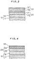
- the electrostatic shiedling layer 20 and the magnetic shielding layer 30 are of double layer construction consisting of metal layers 21, 31 and polyester layers 22, 32, respectively, as shown in Fig. 3.
- the double layer construction is adopted for the purpose of reinforcing the metal layers with the polyester layers for enhancement of workability because a single metal layer, if provided, is very disadvantageous in strength.
- the metal layer 21 is typically made of a metal of good electric conductivity such as copper and aluminum.
- the metal layer 31 is typically made of a metal of high magnetic permeability such as iron and nickel.
- the respective metal layers 21 and 31 are 20 ⁇ m or less in thickness. The thicker the metal layers 21 and 31 are, the greater the shielding effects thereof are. However, too great thickness of the metal layers 21 and 31 impairs the flexibility of the wire harness.
- Polyimide layers or polyvinyl chloride layers may be substituted for the polyester layers 22 and 32. Polyester layers are, however, more advantageous in consideration for costs and strength.
- the electrostatic shielding layer 20 having the metal foil of good electric conductivity and the magnetic shielding layer 30 having the metal foil of high magnetic permeability coat the wire 10 independently in the first preferred embodiment, which requires two working steps.
- the metal foils may be formed integrally to reduce the working steps.
- metal of high magnetic permeability should be plated or deposited on an electrostatic shielding layer 23 of good electric conductivity consisting of a metal layer 24 and a polyester layer 25 to form a magnetic shielding layer 33, as shown in Fig. 4.
- the metal layer 24 is made of copper or aluminum and the magnetic shielding layer 33 is made of nickel or iron.
Landscapes
- Physics & Mathematics (AREA)
- Electromagnetism (AREA)
- Insulated Conductors (AREA)
Claims (6)
- Kabelbaum miteiner Vielzahl von abgeschirmten Leitungen bzw. Drähten (1), die zu einem Bündel geformt sind, und Verbindern (2), die jeweils an gegenüberliegende Enden der abgeschirmten Leitungen (1) angeschlossen sind, wobeijede der abgeschirmten Leitungen (1) eine isolierend beschichtete Leitung (10), eine elektrostatische Abschirmschicht (20, 23), die die isolierend beschichtete Leitung (10) über ihre gesamte Länge bedeckt, und eine magnetische Abschirmschicht (30, 33), die die elektrostatische Abschirmschicht (30, 33) über ihre gesamte Länge bedeckt, umfaßt, unddie elektrostatische Abschirmschicht (20, 23) aus einer ersten Metallfolie mit guter elektrischer Leitfähigkeit und die magnetische Abschirmschicht (30, 33) aus einer zweiten Metallfolie mit hoher magnetischer Permeabilität ausgebildet, und die Vielzahl von abgeschirmten Leitungen bzw. Drähten (1) mit Klebebändern (3) gebündelt sind.
- Kabelbaum nach Anspruch 1, wobei die elektrostatische Abschirmschicht (20, 23) aus einer Doppelschichtkonstruktion bestehend aus einer ersten Metallschicht (21, 24) und einer ersten Polyesterschicht (22, 25) besteht.
- Kabelbaum nach Anspruch 1 oder 2, wobei die elektrostatische Abschirmschicht (23) und die magnetische Abschirmschicht (33) einheitlich geformt sind, wobei die zweite Metallfolie (23) mit hoher magnetischer Permeabilität auf die erste Metallfolie (24) mit guter elektrischer Leitfähigkeit plattiert oder aufgedampft ist.
- Kabelbaum nach einem der Ansprüche 1 oder 2, wobei die magnetische Abschirmschicht (30, 70) aus einer Doppelschichtkonstruktion bestehend aus einer zweiten Metallschicht (31) und einer zweiten Polyesterschicht (32) besteht.
- Kabelbaum nach einem der vorhergehenden Ansprüche, wobei die erste Metallschicht (21, 24) aus Kupfer oder Aluminium und die zweite Metallschicht (31) aus Eisen oder Nickel besteht.
- Kabelbaum nach einem der vorhergehenden Ansprüche, wobei die Dicke jeder der ersten und zweiten Metallschichten (21, 31; 24, 31) nicht mehr als 20µm beträgt.
Applications Claiming Priority (3)
| Application Number | Priority Date | Filing Date | Title |
|---|---|---|---|
| JP31783192 | 1992-11-02 | ||
| JP4317831A JPH06150732A (ja) | 1992-11-02 | 1992-11-02 | ワイヤーハーネス |
| JP317831/92 | 1992-11-02 |
Publications (2)
| Publication Number | Publication Date |
|---|---|
| EP0597324A1 EP0597324A1 (de) | 1994-05-18 |
| EP0597324B1 true EP0597324B1 (de) | 2000-04-19 |
Family
ID=18092539
Family Applications (1)
| Application Number | Title | Priority Date | Filing Date |
|---|---|---|---|
| EP93117443A Expired - Lifetime EP0597324B1 (de) | 1992-11-02 | 1993-10-27 | Kabelbaum |
Country Status (4)
| Country | Link |
|---|---|
| US (1) | US5374778A (de) |
| EP (1) | EP0597324B1 (de) |
| JP (1) | JPH06150732A (de) |
| DE (1) | DE69328404T2 (de) |
Cited By (1)
| Publication number | Priority date | Publication date | Assignee | Title |
|---|---|---|---|---|
| TWI623944B (zh) * | 2013-02-21 | 2018-05-11 | Zhizhao Luo | Copper and aluminum alloy used together |
Families Citing this family (39)
| Publication number | Priority date | Publication date | Assignee | Title |
|---|---|---|---|---|
| JP3087883B2 (ja) * | 1994-03-25 | 2000-09-11 | エム・アイ・シー株式会社 | ケーブル圧接ハーネスの製造方法 |
| US5571992A (en) * | 1994-10-25 | 1996-11-05 | Mcdonnell Douglas Helicopter Co. | Lightweight shielded cable assembly |
| JPH09189740A (ja) * | 1996-01-10 | 1997-07-22 | Harness Sogo Gijutsu Kenkyusho:Kk | ワイヤーハーネスの故障位置検出装置 |
| US5917151A (en) * | 1997-08-29 | 1999-06-29 | Ut Automotive Dearborn, Inc. | Multi-shot molds for manufacturing wire harnesses |
| JPH11260160A (ja) * | 1998-03-06 | 1999-09-24 | Murata Mfg Co Ltd | 放射ノイズ抑制用磁性複合テープ及びこの複合テープを用いた放射ノイズ抑制部品 |
| US6201190B1 (en) * | 1998-09-15 | 2001-03-13 | Belden Wire & Cable Company | Double foil tape coaxial cable |
| AUPP814899A0 (en) * | 1999-01-14 | 1999-02-04 | Alcatel | Emi filtering of multi-wire cables |
| JP2001256842A (ja) * | 2000-03-14 | 2001-09-21 | Yazaki Corp | ワイヤハーネスの検査方法 |
| DE10193456T1 (de) * | 2000-08-18 | 2002-10-24 | Mitsubishi Electric Corp | Abgeschirmter Draht, Verfahren zur Herstellung eines abgeschirmten Drahtes und Leuchtvorrichtung für eine Entladungslampe, welche den abgeschirmten Draht verwendet |
| JP2002280121A (ja) * | 2001-03-19 | 2002-09-27 | Jst Mfg Co Ltd | 電気コネクタ、および伝送路 |
| JP4914539B2 (ja) | 2001-05-18 | 2012-04-11 | 矢崎総業株式会社 | シールドハーネスの組立方法 |
| JP2003036730A (ja) * | 2001-07-24 | 2003-02-07 | Ricoh Co Ltd | 電子機器のワイヤハーネス |
| US6552270B1 (en) | 2002-08-08 | 2003-04-22 | Donald W. Heacox | Harness apparatus |
| US7877150B2 (en) | 2004-03-30 | 2011-01-25 | Medtronic, Inc. | Lead electrode for use in an MRI-safe implantable medical device |
| US7844344B2 (en) * | 2004-03-30 | 2010-11-30 | Medtronic, Inc. | MRI-safe implantable lead |
| US8989840B2 (en) | 2004-03-30 | 2015-03-24 | Medtronic, Inc. | Lead electrode for use in an MRI-safe implantable medical device |
| US7844343B2 (en) | 2004-03-30 | 2010-11-30 | Medtronic, Inc. | MRI-safe implantable medical device |
| US9155877B2 (en) | 2004-03-30 | 2015-10-13 | Medtronic, Inc. | Lead electrode for use in an MRI-safe implantable medical device |
| US20060022789A1 (en) * | 2004-05-26 | 2006-02-02 | Kolasinski John R | Charge dissipative electrical interconnect |
| US8280526B2 (en) | 2005-02-01 | 2012-10-02 | Medtronic, Inc. | Extensible implantable medical lead |
| US7853332B2 (en) | 2005-04-29 | 2010-12-14 | Medtronic, Inc. | Lead electrode for use in an MRI-safe implantable medical device |
| US8027736B2 (en) * | 2005-04-29 | 2011-09-27 | Medtronic, Inc. | Lead electrode for use in an MRI-safe implantable medical device |
| US10537730B2 (en) | 2007-02-14 | 2020-01-21 | Medtronic, Inc. | Continuous conductive materials for electromagnetic shielding |
| US9044593B2 (en) | 2007-02-14 | 2015-06-02 | Medtronic, Inc. | Discontinuous conductive filler polymer-matrix composites for electromagnetic shielding |
| US8483842B2 (en) | 2007-04-25 | 2013-07-09 | Medtronic, Inc. | Lead or lead extension having a conductive body and conductive body contact |
| US9037263B2 (en) | 2008-03-12 | 2015-05-19 | Medtronic, Inc. | System and method for implantable medical device lead shielding |
| WO2010126877A1 (en) | 2009-04-30 | 2010-11-04 | Medtronic, Inc. | Shielding an implantable medical lead |
| JP5566716B2 (ja) * | 2010-02-05 | 2014-08-06 | 矢崎総業株式会社 | ワイヤハーネス |
| JP5766415B2 (ja) * | 2010-07-23 | 2015-08-19 | 矢崎総業株式会社 | ワイヤハーネス |
| EP2466702A1 (de) * | 2010-12-14 | 2012-06-20 | Tyco Electronics Nederland B.V. | Verfahren und Vorrichtung zur Herstellung einer Kabelanordnung |
| WO2013158189A1 (en) | 2012-04-19 | 2013-10-24 | Medtronic, Inc. | Paired medical lead bodies with braided conductive shields having different physical parameter values |
| MX2014015451A (es) | 2012-07-31 | 2015-07-14 | Mitsubishi Materials Corp | Alambre de aleacion de cobre y metodo de fabricacion de alambre de aleacion de cobre. |
| US9993638B2 (en) | 2013-12-14 | 2018-06-12 | Medtronic, Inc. | Devices, systems and methods to reduce coupling of a shield and a conductor within an implantable medical lead |
| WO2016014427A1 (en) | 2014-07-23 | 2016-01-28 | Medtronic, Inc. | Methods of shielding implantable medical leads and implantable medical lead extensions |
| WO2016014816A1 (en) | 2014-07-24 | 2016-01-28 | Medtronic, Inc. | Methods of shielding implantable medical leads and implantable medical lead extensions |
| US9446565B2 (en) * | 2014-08-27 | 2016-09-20 | Schlumberger Technology Corporation | Steel armor wire coatings |
| TWM545344U (zh) * | 2016-12-12 | 2017-07-11 | 品威電子國際股份有限公司 | 軟性排線結構和軟性排線電連接器固定結構 |
| JP6908580B2 (ja) * | 2018-12-27 | 2021-07-28 | 矢崎総業株式会社 | 樹脂組成物、被覆電線及びワイヤーハーネス |
| CN109979673A (zh) * | 2019-02-18 | 2019-07-05 | 济宁市海富电子科技有限公司 | 一种数据线缆及其制造方法 |
Family Cites Families (22)
| Publication number | Priority date | Publication date | Assignee | Title |
|---|---|---|---|---|
| BE472664A (de) * | 1945-05-10 | |||
| US3555169A (en) * | 1968-01-02 | 1971-01-12 | Texas Instruments Inc | Composite layer material having an outer layer of copper and successive layer of stainless steel, low carbon steel and copper |
| DE2053424C3 (de) * | 1970-10-30 | 1975-05-28 | Kabel- Und Metallwerke Gutehoffnungshuette Ag, 3000 Hannover | Abschirmung für Nachrichtenkabel zur Verlegung im EinfluBbereich von Starkstromeinrichtungen |
| DE2654880C3 (de) * | 1976-12-03 | 1979-05-31 | Kabel- Und Metallwerke Gutehoffnungshuette Ag, 3000 Hannover | Symmetrisches Fernmeldekabel zur Übertragung von PCM-Signalen |
| US4340771A (en) * | 1981-03-16 | 1982-07-20 | Siecor Corporation | Communications cable having combination shielding-armor member |
| DE8130042U1 (de) * | 1981-10-09 | 1982-12-23 | Siemens AG, 1000 Berlin und 8000 München | Bewegliche elektrische Leitung |
| DE3620595A1 (de) * | 1985-07-26 | 1987-02-05 | Mitec Moderne Ind Gmbh | Kabel |
| GB8601270D0 (en) * | 1986-01-20 | 1986-02-26 | Raychem Ltd | High frequency attenuation cable |
| US4694122A (en) * | 1986-03-04 | 1987-09-15 | Cooper Industries, Inc. | Flexible cable with multiple layer metallic shield |
| US4822956A (en) * | 1986-08-11 | 1989-04-18 | American Telephone And Telegraph Company | Coaxial cable |
| US4835394A (en) * | 1987-07-31 | 1989-05-30 | General Electric Company | Cable assembly for an electrical signal transmission system |
| JPH059782Y2 (de) * | 1987-12-04 | 1993-03-10 | ||
| JP2870761B2 (ja) * | 1988-07-04 | 1999-03-17 | 日本エー・エム・ピー株式会社 | 電気ハーネスの製造装置 |
| DE3914931A1 (de) * | 1989-05-06 | 1990-11-08 | Messerschmitt Boelkow Blohm | Einrichtung zum schutz elektrischer anlagen gegen elektromagnetische stoerungen |
| JPH03120624A (ja) * | 1989-10-04 | 1991-05-22 | Matsushita Electric Ind Co Ltd | 光ピックアップ装置 |
| GB2249212B (en) * | 1990-08-21 | 1994-06-01 | Yoshida Kogyo Kk | Metal-shielded cable suitable for electronic devices |
| US5191173A (en) * | 1991-04-22 | 1993-03-02 | Otis Engineering Corporation | Electrical cable in reeled tubing |
| US5132490A (en) * | 1991-05-03 | 1992-07-21 | Champlain Cable Corporation | Conductive polymer shielded wire and cable |
| US5171937A (en) * | 1991-07-22 | 1992-12-15 | Champlain Cable Corporation | Metal-coated shielding materials and articles fabricated therefrom |
| JP3124419B2 (ja) * | 1993-06-24 | 2001-01-15 | 鹿島建設株式会社 | 建屋の熱溜り空間の換気システム |
| JP3100322B2 (ja) * | 1995-10-03 | 2000-10-16 | 三菱重工業株式会社 | 河川水位予測装置 |
| KR100298439B1 (ko) * | 1998-06-30 | 2001-08-07 | 김영환 | 비휘발성 강유전체 메모리 |
-
1992
- 1992-11-02 JP JP4317831A patent/JPH06150732A/ja active Pending
-
1993
- 1993-10-19 US US08/139,280 patent/US5374778A/en not_active Expired - Lifetime
- 1993-10-27 DE DE69328404T patent/DE69328404T2/de not_active Expired - Lifetime
- 1993-10-27 EP EP93117443A patent/EP0597324B1/de not_active Expired - Lifetime
Cited By (1)
| Publication number | Priority date | Publication date | Assignee | Title |
|---|---|---|---|---|
| TWI623944B (zh) * | 2013-02-21 | 2018-05-11 | Zhizhao Luo | Copper and aluminum alloy used together |
Also Published As
| Publication number | Publication date |
|---|---|
| EP0597324A1 (de) | 1994-05-18 |
| DE69328404D1 (de) | 2000-05-25 |
| US5374778A (en) | 1994-12-20 |
| JPH06150732A (ja) | 1994-05-31 |
| DE69328404T2 (de) | 2000-11-23 |
Similar Documents
| Publication | Publication Date | Title |
|---|---|---|
| EP0597324B1 (de) | Kabelbaum | |
| EP0366046B1 (de) | Abgeschirmtes Flachkabel | |
| CA1191914A (en) | Shielded twisted-pair flat electrical cable | |
| US3340353A (en) | Double-shielded electric cable | |
| EP0300334B1 (de) | Verwendung eines Koaxialkabels | |
| CA2479255C (en) | Twisted pair cable with cable separator | |
| US20040026101A1 (en) | Parallel two-core shielding wire and method for producing the same | |
| CN101740165A (zh) | 柔性电缆 | |
| JPH09308042A (ja) | 電線のシールド構造 | |
| MX2007015040A (es) | Montaje de cable. | |
| US5132489A (en) | Shielded electric cable | |
| US5457287A (en) | Coaxial electrical cable | |
| JPH0561726B2 (de) | ||
| DE102020004613A1 (de) | Gespleisstes kabel, insbesondere gespleisstes hochspannungskabel, und verfahren zum spleissen eines kabels, insbesondere eines hochspannungskabels | |
| US20240212880A1 (en) | Flexible flat wire cable with high frequency conductors | |
| JPH0741051Y2 (ja) | シールド付フラットケーブル | |
| JP7226914B2 (ja) | 配索材の製造方法 | |
| CN213070660U (zh) | 一种带状电缆 | |
| JPH06176633A (ja) | ワイヤーハーネスのシールド方法 | |
| JPH0741053Y2 (ja) | 多心シールドケーブル | |
| JP2003045241A (ja) | シールドフラット電線及びその製造方法 | |
| JPH09331182A (ja) | ケーブル遮蔽用テープ | |
| JP2979883B2 (ja) | シールド付フラットケーブル | |
| JP2906801B2 (ja) | シールド付リボンケーブルの製造方法 | |
| JPH0715050Y2 (ja) | フラツトケ−ブル |
Legal Events
| Date | Code | Title | Description |
|---|---|---|---|
| PUAI | Public reference made under article 153(3) epc to a published international application that has entered the european phase |
Free format text: ORIGINAL CODE: 0009012 |
|
| AK | Designated contracting states |
Kind code of ref document: A1 Designated state(s): DE FR GB |
|
| 17P | Request for examination filed |
Effective date: 19940825 |
|
| 17Q | First examination report despatched |
Effective date: 19950824 |
|
| GRAG | Despatch of communication of intention to grant |
Free format text: ORIGINAL CODE: EPIDOS AGRA |
|
| GRAG | Despatch of communication of intention to grant |
Free format text: ORIGINAL CODE: EPIDOS AGRA |
|
| GRAH | Despatch of communication of intention to grant a patent |
Free format text: ORIGINAL CODE: EPIDOS IGRA |
|
| GRAH | Despatch of communication of intention to grant a patent |
Free format text: ORIGINAL CODE: EPIDOS IGRA |
|
| GRAH | Despatch of communication of intention to grant a patent |
Free format text: ORIGINAL CODE: EPIDOS IGRA |
|
| GRAH | Despatch of communication of intention to grant a patent |
Free format text: ORIGINAL CODE: EPIDOS IGRA |
|
| GRAA | (expected) grant |
Free format text: ORIGINAL CODE: 0009210 |
|
| AK | Designated contracting states |
Kind code of ref document: B1 Designated state(s): DE FR GB |
|
| ET | Fr: translation filed | ||
| REF | Corresponds to: |
Ref document number: 69328404 Country of ref document: DE Date of ref document: 20000525 |
|
| PLBE | No opposition filed within time limit |
Free format text: ORIGINAL CODE: 0009261 |
|
| STAA | Information on the status of an ep patent application or granted ep patent |
Free format text: STATUS: NO OPPOSITION FILED WITHIN TIME LIMIT |
|
| 26N | No opposition filed | ||
| REG | Reference to a national code |
Ref country code: GB Ref legal event code: IF02 |
|
| PGFP | Annual fee paid to national office [announced via postgrant information from national office to epo] |
Ref country code: DE Payment date: 20121024 Year of fee payment: 20 Ref country code: FR Payment date: 20121018 Year of fee payment: 20 |
|
| PGFP | Annual fee paid to national office [announced via postgrant information from national office to epo] |
Ref country code: GB Payment date: 20121024 Year of fee payment: 20 |
|
| REG | Reference to a national code |
Ref country code: DE Ref legal event code: R071 Ref document number: 69328404 Country of ref document: DE |
|
| REG | Reference to a national code |
Ref country code: DE Ref legal event code: R071 Ref document number: 69328404 Country of ref document: DE |
|
| REG | Reference to a national code |
Ref country code: GB Ref legal event code: PE20 Expiry date: 20131026 |
|
| PG25 | Lapsed in a contracting state [announced via postgrant information from national office to epo] |
Ref country code: DE Free format text: LAPSE BECAUSE OF EXPIRATION OF PROTECTION Effective date: 20131029 Ref country code: GB Free format text: LAPSE BECAUSE OF EXPIRATION OF PROTECTION Effective date: 20131026 |