EP0597434A2 - Vakuumschalter - Google Patents
Vakuumschalter Download PDFInfo
- Publication number
- EP0597434A2 EP0597434A2 EP93118102A EP93118102A EP0597434A2 EP 0597434 A2 EP0597434 A2 EP 0597434A2 EP 93118102 A EP93118102 A EP 93118102A EP 93118102 A EP93118102 A EP 93118102A EP 0597434 A2 EP0597434 A2 EP 0597434A2
- Authority
- EP
- European Patent Office
- Prior art keywords
- electrode
- coil
- arc
- main
- vacuum interrupter
- Prior art date
- Legal status (The legal status is an assumption and is not a legal conclusion. Google has not performed a legal analysis and makes no representation as to the accuracy of the status listed.)
- Granted
Links
Images
























Classifications
-
- H—ELECTRICITY
- H01—ELECTRIC ELEMENTS
- H01H—ELECTRIC SWITCHES; RELAYS; SELECTORS; EMERGENCY PROTECTIVE DEVICES
- H01H33/00—High-tension or heavy-current switches with arc-extinguishing or arc-preventing means
- H01H33/60—Switches wherein the means for extinguishing or preventing the arc do not include separate means for obtaining or increasing flow of arc-extinguishing fluid
- H01H33/66—Vacuum switches
- H01H33/664—Contacts; Arc-extinguishing means, e.g. arcing rings
- H01H33/6644—Contacts; Arc-extinguishing means, e.g. arcing rings having coil-like electrical connections between contact rod and the proper contact
-
- H—ELECTRICITY
- H01—ELECTRIC ELEMENTS
- H01H—ELECTRIC SWITCHES; RELAYS; SELECTORS; EMERGENCY PROTECTIVE DEVICES
- H01H33/00—High-tension or heavy-current switches with arc-extinguishing or arc-preventing means
- H01H33/60—Switches wherein the means for extinguishing or preventing the arc do not include separate means for obtaining or increasing flow of arc-extinguishing fluid
- H01H33/66—Vacuum switches
- H01H33/664—Contacts; Arc-extinguishing means, e.g. arcing rings
- H01H33/6644—Contacts; Arc-extinguishing means, e.g. arcing rings having coil-like electrical connections between contact rod and the proper contact
- H01H33/6645—Contacts; Arc-extinguishing means, e.g. arcing rings having coil-like electrical connections between contact rod and the proper contact in which the coil like electrical connections encircle at least once the contact rod
Definitions
- the present invention relates generally to a vacuum interrupter which is used in a vacuum circuit breaker or the like, and more particularly to a vacuum interrupter having an electrode-structure which generates a magnetic field in the direction parallel to an electric arc generated after disconnection of the vacuum interrupter.
- a vacuum interrupter for interrupting a heavy-current in an evacuated envelope diffusion of an arc generated after disconnection operation of the vacuum interrupter have been studied in order to improve interruption characteristic thereof.
- the diffusion of the arc is performed by a magnetic field which is generated by an arc current flowing after the disconnection operation.
- a conventional vacuum interrupter comprising such an arc diffusion means is elucidated hereafter with reference to FIGs. 57, 58 and 59.
- FIG.57 is a cross-section of a side view showing schematic structure of the conventional vacuum interrupter.
- an evacuated envelope 4 is composed of a cylindrical insulating container 1 and end plates 2 and 3 for sealing both ends of the insulating container 1.
- a disc-shaped stationary electrode assembly 6 connected to a stationary electrode rod 5 and a disc-shaped movable electrode assembly 7 connected to a movable electrode rod 8 are arranged in opposed relationship in the evacuated envelope 4.
- the movable electrode assembly 7 is constructed so as to connect or disconnect with respect to the stationary electrode assembly 6 by an operation mechanism (not shown) connected mechanically to the movable electrode rod 8.
- a bellows 10 is disposed between the end plate 3 and the movable electrode rod 8, and thereby air-tightness of the evacuated envelope 4 is maintained and the movable electrode rod 8 is permitted to move in the axial direction (upward or downward in FIG.57).
- a shield 9 is arranged in a manner of surrounding the stationary electrode assembly 6 and the movable electrode assembly 7 in the evacuated envelope 4.
- the magnetic field in the axial direction serves to diffuse a plasma arc produced between both the electrode assemblies onto entire surfaces of the stationary electrode assembly 6 and the movable electrode assembly 7 which are arranged in opposed relationship.
- An arc voltage across the stationary electrode assembly 6 and the movable electrode assembly 7 is decreased by diffusing the plasma arc during the disconnection operation, and a temperature rise in both the electrode assemblies is significantly suppressed.
- FIG.58 is an exploded perspective assembly view of a movable electrode assembly 7 in the vacuum interrupter of the United States Patent No. 4,473,731, and FIG.59 is a plan view of the movable electrode assembly 7 shown in FIG.58.
- a movable electrode 21 is mounted on the top of a movable electrode rod 8 through a short circuit member 22, and is supported at the central part by a support member 23 which is made of high resistance material and fixed on the movable electrode rod 8.
- Four arms 21 a are formed on the peripheral portion of the movable electrode 21 along the circumference thereof.
- four arms 22a extending in radial directions are formed on the short circuit member 22. The ends of the arms 22a of the short circuit member 22 contact the respective arms 21 a of the movable electrode 21, and the movable electrode 21 is electrically connected to the short circuit member 22.
- the movable electrode assembly 7 comprising the movable electrode 21, the movable electrode rod 8, the short circuit member 22 and the support member 23 shown in FIG.58 is arranged in the evacuated envelope 4 in opposed relationship to the stationary electrode assembly 6 as shown in FIG.57.
- FIG.59 current paths of the arc current are illustrated by arrows.
- the arc current flows from the central part P of the movable electrode 21 to the connection parts of the arms 21 a in the radial direction as shown by arrows X, and passes through the arms 21 a along the circumference of the movable electrode 21 as shown by arrows Y. Subsequently, the arc current flows to the movable electrode rod 8 through the arms 22a of the short circuit member 22 in the radial directions as shown by arrows Z. Consequently, four fan-shaped current paths are formed as shown in the plan view of FIG.59, and magnetic fields in the axial direction are generated in these fan-shaped regions by the known right-handed screw rule.
- the plasma arc produced between the stationary electrode assembly 6 and the movable electrode assembly 7 is diffused by the magnetic field.
- the intensity of the magnetic field in the fan-shaped region is larger than that in the region between neighboring two fan-shaped regions. Therefore, the intensity of the magnetic field is not uniform between the stationary electrode assembly 6 and the movable electrode assembly 7, and the plasma arc is not effectively diffused owing to the lack of uniformity of the magnetic field.
- An object of the present invention is to provide a vacuum interrupter in which a uniform magnetic field is generated between a stationary electrode and a movable electrode by guiding an arc current along full circumference of the stationary electrode and the movable electrode.
- the vacuum interrupter in accordance with the present invention comprises:
- the coil part arranged along the circumference of the coil electrode is protruded to the back surface of the main electrode and contacts the main electrode Therefore, the magnetic field in the axial direction of the coil electrode is enhanced, and leak of magnetic flux decreases. Consequently, suitable distribution of the magnetic field is realizable, and the arc in disconnection operation is effectively diffused. And thereby the vacuum interrupter having superior disconnection characteristic can be provided. Moreover, the vacuum interrupter which is superior in mechanical strength of the coil electrode can be provided.
- a coil cover covers a part having a high electric potential such as an arc-shaped part and a slit part of the coil electrode which deteriorates a withstand voltage characteristic, the part is not exposed between both the main electrodes, and thus the withstand voltage characteristic of the electrodes is totally improved.
- FIG.1 is a perspective view illustrating electrode assemblies in the vacuum interrupter of the first embodiment
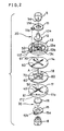
- FIG.2 is an exploded perspective assembly view of the electrode assemblies in FIG.1.
- the electrode assemblies of the vacuum interrupter shown in FIG.1 are arranged in an evacuated envelope and are structured so as to connect or disconnect with each other by an operation mechanism (not shown).
- the electrode assemblies shown in FIG.1 comprise a stationary electrode assembly 20 fixed on the evacuated envelope through an insulating member and a movable electrode assembly 30 which moves upward or downward by activation of the operation mechanism (not shown) and connects or disconnects with the stationary electrode assembly 20.
- the stationary electrode assembly 20 is substantially identical with the movable electrode assembly 30 in structure, and one of them is inverted and is arranged in opposed relationship to the other. Therefore configuration of only the stationary electrode assembly 20 is elucidated in detail.
- the stationary electrode assembly 20 comprises a stationary electrode rod 5, a stationary connection conductor 11, a support member 12, a stationary coil electrode 13 and a stationary main electrode 14; and the movable electrode assembly 30 comprises a movable electrode rod 8, a movable connection conductor 15, a support member 16, a movable coil electrode 17 and a movable main electrode 18.
- the stationary connection conductor 11 comprises a ring-shaped holding part 11 a which is put on a boss 5a of the stationary electrode rod 5 and an arm part 11 extended outward in a radial direction.
- a gap 61 (cut-part) is formed by cutting out a part of the circumference of a ring-shaped coil part 13a placed on the peripheral portion of the stationary coil electrode 13.
- An end of the arm part 11 b is electrically connected to the coil part 13a at the inside wall of a connecting part 13z in the vicinity of the gap 61.
- a circular pit 13b is formed inward from the coil part 13a of the stationary coil electrode 13, and a thickness of the circular pit 13b in the axial direction is thinner than that of the coil part 13a in the axial direction.
- a straight slot 40 is formed on the circular pit 13b in a manner of passing through the center of the circular pit 13b and communicating with the gap 61 of the coil part 13a.
- the length of the slot 40 is equal to the inner diameter of the coil part 13a or shorter than that.
- another slot 50 intersects perpendicularly with the slot 40 at the center of the circular pit 13b and the length of the slot 50 is equal to the inner diameter of the coil part 13a or shorter than that.
- the support member 12 supports the stationary coil electrode 13 by contacting with a hole 13c formed in the circular pit 13b of the stationary coil electrode 13.
- the support member 12 is made of high-resistance material such as stainless steel.
- a shaft 12a of the support member 12 is inserted in a hole of the boss 5a of the stationary electrode rod 5.
- Slots 60 and 70 having the same shape as the slots 40 and 50 of the stationary coil electrode 13 are formed on the disc-shaped stationary main electrode 14 which is mounted on the surface of the stationary coil electrode 13 facing to the movable electrode assembly 30.
- the stationary main electrode 14 is fixed on the stationary coil electrode 13 in a manner that the slots 40 and 50 of the stationary coil electrode 13 overlap the slots 60 and 70 of the stationary main electrode 14, respectively.
- the stationary main electrode 14 and the movable main electrode 18 are provided with salient contacts 80 on the respective central surfaces, and an electric arc is produced on the salient contacts 80 between both the main electrodes.
- the arm part 11 b is connected to the coil part 13a at the connecting part 13z, and in a similar manner, an arm part 15b of a movable connection conductor 15 in the movable electrode assembly 30 is electrically connected to a coil part 17a of the movable electrode assembly 30 at a connecting part 17z.
- the connecting part 13z and the connecting part 17z are arranged in the vicinity of opposed sides of a plane passing through both the gaps 61 and the centers of the coil parts 13a and 17a.
- the stationary main electrode 14, the movable main electrode 18 and the salient contacts 80 are made of the following various materials corresponding to a capacity and intended purpose of the vacuum interrupter:
- FIG.2 when the electric arc A is generated between the stationary main electrode 14 and the movable main electrode 18, the current flows from the stationary electrode rod 5 to the coil part 13a via the stationary connection conductor 11, and reaches an arc generation point.
- the current flows from the arc generation point to the radial direction in the movable main electrode 18 and passes the coil part 17a.
- the current flows from the end part of the coil part 17a to the movable connection conductor 15 and reaches the movable electrode rod 8.
- the current at generation of the arc passes the coil parts 13a and 17a arranged on the respective circumferential parts of the coil electrodes 13 and 17, the flowing directions of the current are identical with each other on both the coil parts 13a and 17a, and their paths are substantially circular. Consequently, a magnetic field in the axial direction is generated between the main electrodes in generation of the arc.
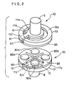
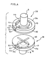
- FIGs. 3 and 4 are perspective views of examples of the electrodes assemblies in the first embodiment.
- plural salient contacts 80a are formed on the surface of the stationary main electrode 85 and a hidden surface of the movable main electrode 86 of the respective electrode assemblies which are opposed with each other, and thereby positions generating the arc are decided between both the electrodes.
- the electrode assemblies shown in FIG.4 comprise a disc-shaped stationary main electrode 92 and a disc-shaped movable main electrode 93, and thereby the electrode structure is simplified.
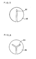
- FIGs. 5, 6 and 7 are plan views of the shapes of the slots which are formed on the respective main electrodes and coil electrodes, and only the respective main electrodes in both the electrode assemblies are shown in these drawings.
- a straight line-shaped slot 82 is formed on the main electrode 88.
- a Y-shaped slot 83 is formed on the main electrode 89.
- a star-shaped opening is formed on the central part of the main electrode 90. The opening 84 is communicated to the outer circumference of the main electrode 90 through a slot 62 formed in the radial direction of the main electrode 90.
- FIG.8 is a perspective view of the electrode assembly in the vacuum interrupter of the second embodiment.
- the vacuum interrupter of the second embodiment shown in FIG.8 comprises a pair of the stationary electrode assembly 20 and the movable electrode assembly 30 which are identical with each other in configuration and arranged in opposed relationship in the evacuated envelope.
- the movable electrode assembly 30 is structured so as to connect or disconnect with the stationary electrode assembly 20 in the same manner as the first embodiment.
- Respective main electrodes 94 and 95 of the stationary electrode assembly 20 and the movable electrode assembly 30 in the second embodiment are made of substantially flat disc-shaped metal plates without a slot.
- the main electrodes 94 and 95 are mounted on the opposing surfaces of the coil electrodes 13 and 17 having a slot. Moreover, edge parts of the opposing surfaces of the disc-shaped main electrodes are formed to curved surfaces, and concentration of an electric field is relaxed between both the main electrodes.
- the main electrodes 94 and 95 in the second embodiment are made of the same material as the main electrodes in the first embodiment.
- a current flow in generation of the electric arc between both the electrode assemblies is elucidated with reference to FIG.8.
- the arc A is generated between the stationary main electrode 94 and the movable main electrode 94, the current flows in the coil parts 13a and 17a located at the peripheral portion of the respective coil electrodes 13 and 17 having a low resistance. Therefore, the current flows on circular paths of the respective electrode assemblies, and the magnetic field in the axial direction is generated between both the electrodes.
- the plasma arc generated between both the electrodes is efficiently diffused by the magnetic field. Since the main electrodes 94 and 95 in the second embodiment are flat-shaped and formed to the curved surfaces on the edge parts of the surfaces, the vacuum interrupter having a high withstand voltage is realizable.
- FIG.9 is a perspective view of the electrode assemblies in the vacuum interrupter of the third embodiment.
- the vacuum interrupter in the third embodiment in FIG.9 comprises a pair of the stationary electrode assembly 20 and the movable electrode assembly 30 which are substantially identical with each other and are arranged in opposed relationship in the evacuated envelope.
- the movable electrode assembly 30 is structured so as to connect or disconnect with the stationary electrode assembly 20.
- the main electrodes 96 and 97 and the coil electrodes 91 and 87 in the respective electrode assemblies are provided with openings 81 at the central parts of the main electrodes 96 and 97 and the coil electrodes 91 and 87 in addition to the radial slots 60 and 70 passing through the central parts.
- the diameters of support members (not shown in FIG.9) for mechanically supporting the main electrodes 96 and 97 and the coil electrodes 91 and 87 are larger than the diameters of the openings 81 in order to close the openings 81.
- the current flow in generation of the electric arc between both the electrode assemblies in the third embodiment is elucidated hereafter with reference to FIG.9.
- the electric arc is not generated at the central part, but is generated in the vicinity of the circumferential part of the main electrodes 96 and 97. Therefore, the current flows rapidly to the coil parts 91 a and 87a which are disposed on the back face of the circumferential parts of the main electrodes 96 and 97, and the current path becomes substantially circular in the main electrodes 96 and 97. Consequently, a uniform magnetic field in the axial direction is generated between both the electrodes, and the plasma arc is effectively diffused.
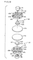
- FIG.10 is an exploded perspective assembly view of the electrode assembly of the vacuum interrupter in the fourth embodiment corresponding to the constitution of claims 4, 5, 6 and 7.
- coil electrodes 43 made of conductive material are provided with ring-shaped holding parts 43a at the central parts which are put on the bosses 5a and 8a of the electrode rods 5 and 8.
- Four arms 43b are extended from the holding part 43a to the radial direction.
- Arc-shaped coil parts 43c are connected to the ends of the respective arms 43b and are arranged on a circular.
- the coil parts 43c are protruded in the axial direction and contact with the back surface of the respective disc-shaped main electrodes 41 at the entire circumferential surfaces 43d.
- Support members 42 mechanically support the back surfaces of the respective main electrodes 41.
- the support members 42 are made of high resistance material such as stainless steel, and rod parts 42a are inserted in a supporting hole 8b of the electrode rods 8 and are fixed thereby.
- a disc-shaped supporting part 42b supports the central part of the main electrodes 41.
- FIG.11 (a) is a perspective view showing disconnection state of the electrode assemblies.
- Currents flow from an arc spot P generated on the main electrode 41 a to the circumference of the main electrode in radial direction as shown by dotted lines.
- the currents reach the coil part 43c of the coil electrode 43, the current flows in the coil part 43c which is lower in resistance than the main electrode 41 a, and reaches the electrode rod 8 through the arm parts 43b and the holding part 43a of the coil electrode 43 shown in FIG.11 (b).
- the current flows in the directions shown by dotted lines with arrow in the other main electrode 41 b. Consequently, the magnetic field in the axial direction is generated between both the main electrodes in a similar manner to the above-mentioned embodiments, and thereby the arc is diffused.
- a cross-shaped good conductivity member 44 for example, is formed on the upper surface 44b of the support member 42 as shown in FIG.12(a) in the fourth embodiment, the main part of the current from the arc spot P flows to the ends of the coil parts 43c through the cross-shaped good conductive member 44 formed on the upper surface of the support member 42. Subsequently, the current flows to the electrode rod 8 through the arm parts 43b of the coil electrode 43 and the holding part 43a.
- the good conductivity member 44 formed on the upper surface of the support member 42 serves to lead the arc current generated on the main electrode 41 to the end of the coil part 43c as much as possible. Consequently, the current flowing the coil part 43c is increased, and the intensity of the magnetic field is increased.
- the good conductivity member 44 may be formed to other shape which can effectively flows the current to the coil part 43c other than the cross, for example may be formed to a disk-shape as shown in FIG.12(b).
- the good conductivity member 44 serves to reduce the resistance between both the electrode assemblies and to suppress the current which leaks to the electrode rod 8 through the main electrodes 41 and the support members 42.
- FIG.12(c) is a partial cross-section of assembled movable electrode assembly 43.
- FIG.13(a) is a perspective view of the electrode assemblies of the vacuum interrupter in the sixth embodiment corresponding to the constitution of claims 4, 5, 6 and 7.
- high resistance parts 45 are slots or fillers made of high resistance material such as stainless steel filled in the slots and are disposed inward from the circumference of the main electrode 41 along the circumference.
- the high resistance parts 45 are formed along the arm parts 43b of the coil electrodes 43 extending to the radial directions and the arm parts 43c extending along the circumference, and are terminated at the positions which are shorter than the arm length of the arm parts 43c.
- other high resistance parts 46 are formed in the radial directions of the main electrode 41.
- the high resistance parts 46 are made of high resistance material such as stainless steel or may be substituted with slits.
- Other configuration in the sixth embodiment is identical with that of the fourth embodiment, and therefore elucidation is omitted.
- the high resistance parts 45 formed along the circumference serve to flow the current along the coil part 43c as much as possible.
- the intensity of the magnetic field generated by the coil electrodes 43 is enhanced, and uniformity of the magnetic field is improved.
- the high resistance parts 46 in the radial directions of the sixth embodiment serve to prevent the reduction of the magnetic field in the axial direction due to the eddy current which is generated on the main electrode 41.
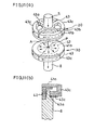
- reentrants 47 are formed on the central contact surfaces of the main electrodes 41 a and 41 b so as to reduce the resistance between both the electrode assemblies and to be easy to move the arc.
- FIG.14(b) is a partial cross-section of the electrode assembly in the example.
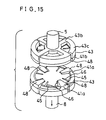
- Protrusions 48 may be formed on the main electrodes 41 a and 41 b as shown in FIG.15 to obtain the same effect as the reentrants 47 in FIG.14(a).
- the number of the arm parts 43b and the coil parts 43c of the coil electrode 43 may be changed in order to vary the intensity of the magnetic field in accordance with the change of operation condition or contact material of the vacuum interrupter. In the above-mentioned case, the same effect is realizable.
- the seventh embodiment in accordance with the invention of claims 8, 9 and 10 is directed to the vacuum interrupter of which the magnetic field in the axial direction between both the electrodes is uniformed, and the plasma arc generated between both the electrodes is effectively diffused.
- the seventh embodiment of the vacuum interrupter in accordance with the present invention of claim 8 is elucidated with reference to drawings.
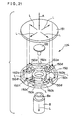
- FIG.16 is a perspective view of the electrode assemblies in the vacuum interrupter of the seventh embodiment
- FIG.17 is an exploded perspective assembly view of a movable electrode assembly 114 in the electrode assemblies shown in FIG.16.
- FIG.18 is a cross-section of the movable electrode assembly 114 shown in FIG.17.
- the electrode assemblies of the vacuum interrupter shown in FIG.16 are arranged in the evacuated envelopes, and are operated to connect or disconnect by an operation mechanism (not shown).
- the electrode assemblies shown in FIG.16 comprise the stationary electrode assembly 113 fixed on the evacuated envelope through an insulating member and the movable electrode assembly 114 which is operated to connect or disconnect with the stationary electrode assembly 113 by up and down operation of the operation mechanism,
- the configuration of the stationary electrode assembly 113 is substantially identical with the configuration of the movable electrode assembly 114.
- the movable electrode assembly 114 comprises the movable electrode rod 8, a coil electrode 130, a main electrode 131 and a support member 132.
- the coil electrode 130 is provided with a ring-shaped holding part 130a which is put on the boss 8a of the movable electrode rod 8 at the central part.
- Four arm parts 130b are extended from the holding parts 130a in the radial directions.
- the arm parts 130b are bent substantially perpendicularly at two positions, and the end faces of the arm parts 130b are connected to respective arc-shaped coil parts 130c.
- Straight parts 130d of the arm parts 130b extended from the holding part 130a in the radial directions are directed to the ends of the coil parts 130c.
- the four coil parts 130c connected to the respective arm part 130b are arranged substantially on the same circumference.
- the upper surfaces of these coil parts 130c are protruded upward from the upper surfaces of the holding parts 130a or the arm parts 130b, and are made to contact the back surface of the disc-shaped main electrode 131 at the entire surface.
- the support member 132 mechanically supports the main electrodes 131 by contacting the back surface of the main electrode 131.
- the support member 132 is made of high resistance material such as stainless steel.
- a rod-shaped shaft part 132a in the axial direction is inserted in a support hole 8b formed in the end part 8a of the movable electrode rod 8 and is fixed thereby.
- arc-shaped arms 131 a are formed on the disc-shaped main electrode 131 which is mounted on the coil electrode 130.
- the four arc-shaped arms 131 a are formed substantially on the same circumference.
- These arc-shaped arms 131 a are positioned so as to overlap on the respective upper surface of the coil part 130c of the coil electrode 130.
- slots 190 are formed on the main electrode 131 in the radial directions, and thereby guide parts 131b are formed so as to communicate from the central part of the arc generating point to the arc-shaped arms 131 a.
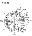
- FIG.19 is a plan view showing the main electrode 131 of the movable electrode assembly 114 in FIG.17 and the coil electrode 130 placed on the back surface thereof.
- the current flows through the main electrode 131 and the coil electrode 130 along the current paths R and reaches the movable electrode rod 8. Namely, the current flows in the radial directions through the guide parts 131 b of the main electrode 131, and reaches the movable electrode rod 8 through the circumferential parts 131 a of the main electrode 131, the coil parts 130c of the coil electrode 130, the arm parts 130b and the holding parts 130a.
- the current flows from the stationary electrode rod 5 to the guide parts 131 b of the main electrode 121 through the holding parts 120a of the coil electrode 120, the arm parts 120b, the coil parts 120c and the circumferential parts 121 a of the main electrode 121.
- the current in the main electrode 121 flows the guide parts 131b in the radial directions and reaches a generation point of the arc A.
- the currents flowing in generation of the arc in the radial directions of the guide parts 131b of the main electrode 131 flow substantially in the reverse directions to the currents flowing the arm parts 130b of the coil electrode 130 placed on the back surface, and the current values are substantially identical with each other. Therefore, the magnetic field generated by the current flowing the guide parts 131b of the main electrode 131 in the radial directions is countervailed by the magnetic field generated by the current flowing the arm parts 130b of the coil electrode 130. In a similar manner, the magnetic field generated by the current flowing the guide part of the main electrode 121 of the stationary electrode assembly 113 in the radial directions is countervailed by the magnetic field generated by the current flowing the arm parts 120b of the coil electrode 120.
- the magnetic field generated by the current flowing the main electrodes 121 and 131 in the respective radial directions in generation of the arc is countervailed by the magnetic field generated by the current flowing the arm parts 120b and 130b of the respective coil electrodes 120 and 130. Consequently, a uniform magnetic field is generated between both the main electrodes in the axial direction by the current flowing the coil parts 120c and 130c of the coil electrodes 120 and 130 and the circumferential parts 121 a and 131 a of the main electrodes 121 and 131. And thereby the plasma arc generated in the disconnection operation is effectively diffused.
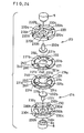
- FIG.20 is a perspective view showing the electrode assemblies of the vacuum interrupter in the eighth embodiment and FIG.21 is an exploded perspective assembly view of the movable electrode assembly 124 in FIG.20.
- elements having the same structure and function as the elements in the seventh embodiment are identified by like numerals, and the elucidation is omitted.
- a stationary electrode assembly 123 and a movable electrode assembly 124 arranged in opposed relationship in the evacuated envelope are substantially made to the same structure and are configurated to connect or disconnect with each other.
- the movable electrode assembly 124 comprises the movable electrode rod 8, the support member 132, a coil electrode 150 and a main electrode 151.
- the coil electrode 150 is provided with a ring-shaped holding part 150a which is put on the boss 8a of the movable electrode rod 8 at the central part.
- Four arm parts 150b are extended from the holding part 150a in the radial directions.
- the arm parts 150b are bent at substantially right angle at two positions and are connected to respective coil parts 150c.
- Four coil parts 150c connected to the respective arm parts 150b are arranged on the same circumference.
- a salient contact part 150d is formed on the end part of each coil part 150c, and the contact parts 150d contact the back surface of the main electrode 151.
- Each arm part 150b extended from the holding part 150a of the coil electrode 150 is positioned in the direction of the contact part 150d connected to other arm part 150b. Consequently, the holding part 150a is connected to the coil part 150c through the bent part.
- the main electrode 151 which contacts the contact parts 150d of the coil electrode 150 is disc-shaped. Material of the main electrode 151 is selected in accordance with the capacity and the intended purpose of the vacuum interrupter in a similar manner of the main electrode 131 in the seventh embodiment.
- the arc A is generated at a position on the main electrode 151 shown by FIGs. 20 and 21, and the current flows on the main electrode 151 and the coil electrode 150 in the directions shown by arrows L. Namely, the current flows in the radial directions on the main electrode 151 and successively, flows to the movable electrode rod 8 through the contact parts 150d, the coil parts 150c, the arm parts 150b and the holding part 150a.
- the current in generation of the arc flows from the stationary electrode rod 5 to the stationary main electrode 141 through the holding part 140a, the arm parts 140b, the coil parts 140c and the contact parts 140d, and successively flows on the main electrode 141 in the radial directions.
- the current flowing on the main electrode 151 in disconnection operation flows the coil parts 150 and the arm parts 150b through the contact parts 150d.
- the directions of the current flowing the arm parts 150b are substantially equal to the directions of the current flowing the main electrode 151 in the radial directions
- the magnetic field generated by the current flowing the main electrode 151 in the radial directions is substantially negated by the magnetic field by the current flowing the arm parts 150b of the coil electrode 150.
- the magnetic field by the current flowing the main electrode 141 in the radial directions is substantially countervailed by the magnetic field by the current flowing the arm parts 140b of the coil electrodes 140.
- a uniform magnetic field in the axial direction is generated between both the main electrodes in disconnection operation by making substantially coincide the extended directions of the respective arm parts 140b and 150b of the coil electrodes 140 and 150 with the directions of the current flowing the main electrodes 141 and 151 in generation of the arc. Consequently, the plasma arc generated in the disconnection operation is effectively diffused.
- FIG.22 is a plan view of the coil electrode 160 of the electrode assembly of the vacuum interrupter in the ninth embodiment.
- elements with the exception of the coil electrode 160 are identical with the elements in the electrode assembly of the vacuum interrupter in the eighth embodiment.
- the coil electrode 160 in the ninth embodiment is provided with a ring-shaped holding part 160a which is put on the movable electrode rod at the central part, and four arm parts 160b extended from the holding part 160a in the radial direction. Furthermore, the coil electrode 160 is provided with first coil parts 160c connected to the arm parts 160b through bent parts and second coil parts 160d connected to the ends of the first coil parts 160c through other bent parts. Four first coil parts 160c and four second coil parts 160d are substantially arranged on the same circumference. Each coil part of the coil electrode 160 is formed by two arc-shaped arms connected by the bent parts. Consequently, double ring-shaped coil parts are formed on the circumferential portion of the coil electrode 160.
- Contact parts 160e are protruded at the respective end parts of the second coil parts 160d in a manner similar to the coil parts 150c in the eighth embodiment.
- the contact parts 160e contact the back surface of the main electrode.
- the arm parts 160b extended from the holding parts 160a are directed to the contact parts 160e of other arm parts 160b.
- the extending directions of the arm parts 160b of the coil electrode 160 are substantially in coincidence with the directions of the current on the main electrode in generation of the arc, and the coil electrode 160 is formed by the double ring-shaped coil parts, a uniform magnetic field having a large intensity is generated in the axial direction, and the plasma arc is effectively diffused.
- the coil electrode has four arm parts
- the number of the arm parts is not limited to four, but plural arm parts may be formed on the coil electrode in the seventh, eighth and ninth embodiments in order to obtain the same effect.
- FIG.23 is a perspective view of the electrode assemblies of the vacuum interrupter in the tenth embodiment
- FIG.24 is an exploded perspective assembly view of the electrode assemblies in FIG.23.
- the electrode assemblies of the vacuum interrupter shown in FIG.23 are enclosed in the evacuated envelope, and are connected or disconnected with each other by an operation mechanism (not shown).
- the electrode assemblies comprise a stationary electrode assembly 213 fixed on the evacuated envelope through an insulating member, a movable electrode assembly 214 which is moved upward to connect or downward to disconnect with the stationary electrode assembly 213 by the operation mechanism.
- the configuration of the stationary electrode assembly 213 is substantially identical with the configuration of the movable electrode assembly 214.
- the stationary electrode assembly 213 comprises the stationary electrode rod 5, a stationary coil electrode 220, a stationary main electrode 221 and a support member 232a.
- the movable electrode assembly 214 comprises the movable electrode rod 8, a movable coil electrode 230, a movable main electrode 231 and a support member 232b.
- the movable coil electrode 230 of the movable electrode assembly 214 is provided with a ring-shaped holding part 230a at the central part which is put on the boss 8a of the movable electrode rod 8.
- Four arm parts 230b are extended in the radial directions from the holding part 230a.
- the end surfaces of the arm parts 230b are connected to ends of respective arc-shaped coil parts 230c, and these four coil parts 230c are arranged substantially on the same circumference.
- the upper surfaces of the coil parts 230c shown in FIG.24 are protruded upward from the holding parts 230a and the arm parts 230b so as to contact the back surface of the disc-shaped movable main electrode 231 at their entire surfaces.
- the movable main electrode 231 comprises first slots formed from the circumference to the vicinity of the center part, second slots 250 formed along the circumference and third slots 260 communicated with the ends of the first slots 250 and formed in the radial direction directed to the center part. Consequently, first arms 231 a extending from the center part to the respective radial directions and arc-shaped second arms 231 b connected to the respective first arms 231 a are formed on the movable main electrode 231. These four second arms 231 b are arranged on the same circumference of the movable main electrode 231.
- a salient contact 234 is formed on the central part of the surface of the movable main electrode 231 opposing to the stationary main electrode 221.
- the salient contact 234 is a place to allow generation of the arc between the stationary main electrode 221 and the movable main electrode 231.
- the movable main electrode 231 of the movable electrode assembly 214 is mechanically supported by a support member 232b which is inserted in a hole 233 (not shown) formed on the central lower face of the movable main electrode 231.
- a shaft 232c of the support member 232b is inserted in the movable electrode rod 8 to support the movable electrode assembly 214.
- the movable main electrode 231 is supported by a detent member (not shown) so as to prevent rotation of the movable main electrode 231 with respect to the stationary main electrode 221. Consequently, the movable main electrode 231 and the stationary main electrode 221 are arranged so as to always oppose at the respective predetermined positions.
- the support member 232b is made a high resistance material such as stainless steel, and thereby a current flowing directly between the movable main electrode 231 and the movable electrode rod 8 is restricted in generation of the arc.
- the stationary electrode assembly 213 substantially has the same structure as the movable main electrode assembly 214, and they are arranged in point symmetry.
- the first arms 221 a of the stationary main electrode 221 and the first arms 231 a of the movable main electrode 231 are extended substantially the same directions.
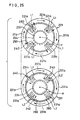
- FIG.25 is a plan view of the stationary main electrode 221 and the movable main electrode 231 with illustration of the current flow.
- the plan view of the stationary main electrode 221 and the movable main electrode 231 is observed from the stationary electrode rod 5 in FIG.24.
- points A are generation points of the arc, and arrows represent the directions of the current.
- the current passed through the arm parts 220b of the stationary coil electrode 220 shown in FIG.24 mounted on the back face of the stationary main electrode 221 flows on the second arms 221 b of the stationary main electrode 221 along the circumference.
- the current passed through the second arms 221 flows to the arc generation point A through the first arms 221 a in the radial direction.
- the current flows from the arc generation point A to the first arms 231 a in the radial directions, and flows to the second arms 231 formed along the circumference.
- the current passed through the second arms 231 b of the movable main electrode 231 flows to the movable electrode rod 8 through the arm parts 230b of the movable coil electrode 230 (shown in FIG.24) mounted on the back face of the movable main electrode 231.
- the currents represented by arrows L1 (hereinafter is referred to as currents L1) flowing the stationary main electrode 221 in the radial directions and the currents represented by arrows L2 (hereinafter is referred to as currents L2) flowing the movable main electrode 231 in the radial directions flow on the paths which are arranged in opposed relationship with each other. Respective directions of the currents L1 and currents L2 are inverted with each other on both the paths. Therefore, the magnetic field generated by the currents L1 flowing the stationary main electrode 221 in the radial directions are countervailed by the magnetic field generated by the currents L2 flowing the movable main electrode 231 in the radial directions.
- FIG.26 is a perspective view of the electrode assemblies of the vacuum interrupter in the eleventh embodiment. Referring to FIG.26 elements having the same structure and function as the elements in the tenth embodiment are identified by like numerals, and the elucidation is omitted.
- the stationary electrode assembly 213 and the movable electrode assembly 214 shown in FIG.26 have substantially the same structure and are arranged in the evacuated envelope in opposed relationship to connect or disconnect with each other.
- the stationary electrode assembly 213 and the movable electrode assembly 214 are located in point symmetry.
- the stationary electrode assembly 213 and the movable electrode assembly 214 in the eleventh embodiment have the same configuration as that of the tenth embodiment.
- the stationary electrode assembly 213 comprises the stationary electrode rod 5, the stationary coil electrode 220, a stationary main electrode 241 and a support member (not shown in FIG.26).
- the movable electrode assembly 214 comprises the movable electrode rod 8, the movable coil electrode 230, a movable main electrode 251 and a support member (not shown in FIG.26).
- the movable main electrode 251 comprises second slots 250 formed along the circumference connected to the first slots 240 formed in the circumferential part in the radial direction, and third slots 260 formed in the directions of the center from the ends of the second slots 250 and fourth slots 290 formed along the circumference connected to the third slots 260. Consequently, first bent arms 251 a and arc-shaped second arms 251 connected to the first arms 251 a are formed on the movable main electrode 251. Four arc-shaped second arms 251 are formed on the same circumference of the movable main electrode 251.
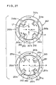
- FIG.27 is a plan view of the stationary main electrode 241 and the movable main electrode 251 for representing the directions of current in generation of the arc.
- the stationary main electrode 241 and the movable main electrode 251 are observed from the stationary electrode rod 5 as shown in FIG.26.
- Points P designate the arc generation points and arrows represent the direction of the current.
- the magnetic field generated by the currents L1 flowing the stationary main electrode 241 in the radial directions are substantially countervailed by the magnetic field generated by the currents L2 flowing the movable main electrode 251 bin the radial directions.
- the current flows the first arms 241 a of the stationary main electrode 241 and the first arms 251 a of the movable main electrode 251 along the circumference, the intensity of the magnetic field in the axial direction is enhanced between both the electrodes.
- plural slots are formed on the stationary main electrode 241 and the movable main electrode 251, and the current paths flowing both the electrodes in the radial directions are regulated in a predetermined regions.
- the movable main electrode 251 is opposed to the stationary main electrode 241 in a predetermined positional relationship with respect to the axes of both the electrodes. Consequently, a uniform magnetic field is generated between both the electrodes in the axial direction in disconnection operation, and the plasma arc generated between both the electrodes is effectively diffused.
- FIG.28 is a plan view of a stationary main electrode 261 and a movable main electrode 271 of other example in the eleventh embodiment.
- slots 261 a and 271 a having shapes shown in FIG.28 are formed on the stationary main electrode 261 and the movable main electrode 271, respectively. Consequently, the current paths flowing the stationary main electrode 261 and the movable main electrode 271 in the radial directions are limited to desired narrow regions. Therefore, the directions of the currents flowing the stationary main electrode 261 in the radial directions are made to just inverse directions to the directions of the current flowing the movable main electrode 271 in the radial directions.
- the magnetic field generated by the current flowing the both the electrodes in the radial directions are perfectly countervailed with each other, and thereby a uniform magnetic field in the axial direction is generated between both the electrodes.
- FIG.29 is a perspective view of the electrode assemblies of the vacuum interrupter in the twelfth embodiment. Referring to FIG.29, elements having the same structure and function as the elements in the tenth embodiment are identified by like numerals and the elucidation is omitted.
- a stationary electrode assembly 213 and a movable electrode assembly 214 shown in FIG.29 are arranged in the evacuated envelope in opposed relationship, and have substantially the same structure.
- the stationary electrode assembly 213 and the movable electrode assembly 214 are configurated to connect or disconnect with each other, and are arranged in point symmetry.
- the stationary coil electrode 282 comprises a ring-shaped holding part 282a which is put on the stationary electrode rod 5 at the center part, four arm parts 282b extended from the holding part 282a in radial directions and four coil parts 282c connected to the respective arm parts 282b.
- a contact part 282d protruded in the direction of the movable electrode assembly 214 is formed on the end part of each coil part 282c of the stationary coil electrode 282.
- the contact part 282d is electrically connected to the stationary main electrode 281.
- a contact part 292d of the movable coil electrode 29protruded in the direction of the stationary electrode assembly 213 is formed on the end part of each coil part 292c thereof.
- the contact part 292d is electrically connected to the movable main electrode 291.
- the contact parts 282d of the stationary coil electrode 282 and the contact parts 292d of the movable coil electrode 292 are protruded in opposed relationship, the current in generation of the arc flows substantially in reverse radial directions with each other at the respective opposing positions of the stationary main electrode 281 and the movable main electrode 291. Therefore, the magnetic field generated by the current flowing the stationary main electrode 281 in the radial directions and the magnetic field generated by the current flowing the movable main electrode 291 in the radial directions are substantially countervailed.
- the stationary electrode assembly 213 and the movable electrode assembly 214 By configurating the stationary electrode assembly 213 and the movable electrode assembly 214 as mentioned above, the current flowing the stationary main electrode 281 and the movable main electrode 291 in substantially radial directions in generation of the arc are countervailed, and a uniform magnetic field in the axial direction is generated between both the electrodes by the current flowing the respective coil parts of both the coil electrodes, and thereby the plasma arc effectively diffused.
- the stationary coil electrode and the movable coil electrode comprise four arm parts
- the number of the arm parts is not limited to four in the present invention.
- a similar effect to the above-mentioned embodiments may be realized by the coil electrodes having plural arm parts.
- a high withstand voltage characteristic is required to withstand a voltage due to a shock wave other than the voltage in the frequency of an electric utility. For this reason, the vacuum interrupter must be configurated so as to maintain the high withstand voltage characteristic between the stationary electrode and the movable electrode.
- the conventional vacuum interrupter having the electrodes for generating the magnetic field in the axial direction since the outer diameter of the main electrode is substantially equal to the outer diameter of the coil electrode, a radius of curvature in the circumferential part of the main electrode must be increased in order to improve the withstand voltage characteristic. In order to increase the radius of curvature, a thickness of the main electrode must be increased, and thus there is a difficulty to miniaturize the vacuum interrupter.
- claims 14, 15 and 16 are directed to obtain the vacuum interrupter improved in the withstand voltage characteristic between both the electrodes and having a superior disconnection characteristic.
- FIG.30 is a perspective view of the electrode assemblies of the vacuum interrupter in the thirteenth embodiment
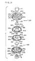
- FIG.31 is an exploded perspective assembly view of the electrode assemblies in FIG.30
- FIG.32 is a cross-section of a movable electrode assembly 330 in FIG.30.
- Both the electrode assemblies of the vacuum interrupter shown in FIG.30 are arranged in the evacuated envelope, and are configurated to connect or disconnect with each other by the operation mechanism (not shown).
- the electrode assemblies comprise a stationary electrode assembly 320 fixed on the evacuated envelope through a insulating member and a movable electrode assembly 330 which is connected or disconnected with the stationary electrode assembly 320 by moving upward or downward by activation of the operation mechanism.
- the configuration of the stationary electrode assembly 320 is substantially identical with that of the movable electrode assembly 330, and one of them is inverted and is arranged in opposed relationship to the other.
- the stationary electrode assembly 320 comprises the stationary electrode rod 5, a stationary coil electrode 311, a support member 312 and a stationary main electrode 313, and the movable electrode assembly 330 comprises the movable electrode rod 8, a movable coil electrode 316, a support member 315 and a movable main electrode 314.
- the stationary coil electrode 311 comprises a ring-shaped holding part 311 a put on the stationary electrode rod 5 at the center part, four arm parts 311 b extended from the holding part 311 a in the radial directions and coil parts 311 connected to the respective arm parts 311 b.
- the movable coil electrode 316 comprise a ring-shaped holding part 316a put on the boss 8a of the movable electrode rod 8 at the center part, and four arm parts 316b extended from the holding part 316a to the radial directions.
- the end surface of each arm part 316b is connected to an end of each arc-shaped coil part 316c, and these coil parts 316c are substantially arranged on the same circumference.
- a circular stepped pit is formed on the upper surface (the face opposed to the stationary electrode assembly 320) of the coil parts 316c, and in which the movable main electrode 314 is inserted.
- the movable main electrode 314 is provided with four arc-shaped circumference parts 314a separated from the movable main electrode 314 by respective slots 390. These circumferential parts 314a of the main electrode 314 is inserted in the stepped pit formed on the upper surface of the coil part 316c of the movable coil electrode 316. Moreover, a salient contact 314b which serves as an arc generation position is formed on the center part of the surface of the movable main electrode 314 opposing to the stationary main electrode 313.
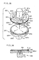
- FIG.32 is a cross-section of the movable electrode assembly 330, showing the state that the movable main electrode 314 is inserted in the movable coil electrode 316.
- the circumferential part of the surface of the movable main electrode 314 opposing to the stationary main electrode 313 is made to a curved surface having a radius of curvature C1 .
- the circumferential part opposing to stationary main electrode 313 of the coil part 316c of the movable coil electrode 316 is made to a curved surface having a radius of curvature C 2 .
- the circumferential edge of the salient contact 314b is made to a curved surface of a radius of curvature C 3 .
- the radius of curvature c 2 of the circumferential part of the coil parts 316c is made to equal to be the radius of curvature C1 of the circumferential part of the movable main electrode 314 or to be larger than the radius of curvature ci .
- the stationary coil electrode 311 and the movable coil electrode 316 are made of alloy of Cu or Ag including Cu, Cu + Cr as main material.
- the support member 315 is made of high resistance material such as stainless steel and mechanically supports the movable main electrode 314 by contacting the lower surface of the movable main electrode 314.
- a dot-shaped shaft 315a extending in the axial direction of the support member 315 is inserted in a support hole formed on the boss 8a of the movable electrode rod 8 and is fixed thereby.
- the vacuum interrupter of the thirteenth embodiment an electric field on the circumferential parts of the electrode assemblies 320 and 330 is relaxed by means of the curved part formed on the circumferential parts of the main electrodes and the coil electrodes. Moreover, since the coil parts 311 c and 316c of the respective coil electrodes 311 and 316 are configurated so as to oppose directly, the magnetic field in the axial direction is effectively generated between both the electrodes. Consequently, the vacuum interrupter of the thirteenth embodiment is superior in the withstand voltage characteristic and disconnection characteristic and is usable for a switch in a high voltage circuit.
- FIG.33 is a perspective view of the electrode assemblies of the vacuum interrupter in the fourteenth embodiment
- FIG.34 is a cross-section of a movable electrode assembly 330 in the electrode assemblies of FIG.33.
- elements having the same structure and function as the elements in the thirteenth embodiment are identified by like numerals and the elucidation is omitted.
- the stationary electrode assembly 320 and the movable electrode assembly 330 shown in FIG.33 are arranged in the evacuated envelope in opposed relationship and have substantially the same structure.
- the movable electrode assembly 330 is configurated to connect or disconnect with the stationary electrode assembly 320, and they are arranged in point symmetry.
- the movable electrode assembly 330 comprises the movable coil electrode 316 having curved circumferential part and a movable main electrode 324 having plural slots 360 in the radial directions.
- the movable main electrode 324 is provided with slots 350 along the circumference.
- the movable main electrode 324 is inserted in the circular stepped pit of the movable coil electrode 316 in a similar manner shown in FIG.33.
- the plural slots 360 formed on the movable main electrode 324 in the radial directions regulate the direction of the current to desired directions in the movable main electrode 324 in generation of the arc. Consequently, a uniform magnetic field in the axial direction is generated between both the electrodes by the current flowing along the circumference of the coil parts 316c of the movable coil electrode 316.
- a cross-shaped conducting member or a disk-shaped conducting member 317 is formed on the upper surface of the support member 315 contacting the movable main electrode 324.
- the conducting member 317 is made of a good conductor and serves to effectively lead the current flowed in the movable main electrode 324 to the circumferential part 324a of the movable main electrode 324.
- the current in generation of the arc is effectively led to the circumferential parts of both the electrodes and the coil parts of both the coil electrodes by contacting the conducting member 317 to the back face of the movable main electrode 324. Thereby the intensity of the magnetic field in the axial direction is enhanced between both the electrodes.
- the radius of curvature c 2 of the circumferential parts of the coil parts 316c is made to be equal to or more than the radius of curvature C1 of the circumferential parts 324a of the movable main electrode 324.
- the vacuum interrupter in the fourteenth embodiment is superior in the withstand voltage characteristic and the disconnection characteristic.
- FIG.35 is a perspective view of the electrode assemblies in the fifteenth embodiment
- FIG.36 is a cross-section of a movable electrode assembly 330 in the electrode assemblies of FIG.35.
- elements having the same structure and function as the elements in the thirteenth embodiment are identified by like numerals and the elucidation is omitted.
- the stationary electrode assembly 320 and the movable electrode assembly 330 and have substantially the same configuration and are arranged in the evacuated envelope in opposed relationship.
- the movable electrode assembly 330 is configurated to connect or disconnect with the stationary electrode assembly 320, and the stationary electrode assembly 320 and the movable electrode assembly 330 are arranged in point symmetry.
- the stationary coil electrode 321 comprises a ring-shaped holding part 321 a put on the stationary electrode rod 5 at the center part, four arm parts 321 b extended from the holding part 321 a in the radial directions and coil parts 321 connected to the respective arm parts 321 b.
- Contact parts 321 d formed at the ends of the coil parts 321 c of the stationary coil electrode 321 are protruded to electrically contact a holding conductor 318 fixed on the back surface (upper surface in FIG.35) of the stationary main electrode.
- FIG.36 is a cross-section of the movable electrode assembly 330 configurated in a manner similar to the stationary electrode assembly 320.
- a holding conductor 318 made of a good conductor is fixed on the back surface (lower surface in FIG.35) of the movable main electrode 334.
- Contact parts 326d formed at the end parts of the coil parts 326c of the movable coil electrode 326 are electrically connected to the holding conductor 318.
- the radius of curvature c 2 of the circumferential part of the holding conductor 318 is made to equal to or more than the radius of curvature C1 of the circumferential part of the movable main electrode 334.
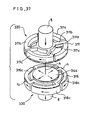
- FIG.37 is a perspective view of the electrode assemblies of the vacuum interrupter in the sixteenth embodiment.
- elements having the same structure and function as the elements of thirteenth embodiment are identified by like numerals and the elucidation is omitted.
- the stationary electrode assembly 320 and the movable electrode assembly 330 shown in FIG.37 have substantially the same structure and are arranged in the evacuated envelope in opposed relationship.
- the movable electrode assembly 330 is configurated to connect or disconnect with the stationary electrode assembly 320.
- the stationary electrode assembly 320 and the movable electrode assembly 330 are arranged in point symmetry.
- a disk-shaped movable main electrode 344 is mounted on the surface opposing to the stationary electrode assembly 320 of the movable coil electrode 316.
- the diameter of the movable main electrode 344 is made to be smaller than the inner diameter of the coil parts 316c of the movable coil electrode 316.
- the radius of curvature c 2 of the circumferential part of the surface opposing to the stationary coil electrode 311 of the movable coil electrode 316 is made to be equal to or larger than the radius of curvature C1 of the circumferential part of the movable main electrode 344. Consequently, in a manner similar to the embodiments as mentioned above, the concentration of the electric field on the opposed surfaces of both the electrode assemblies is relaxed in the sixteenth embodiment.
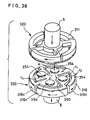
- FIG.38 is a perspective view of an example of the electrode assemblies of the vacuum interrupter in the sixteenth embodiment.
- plural movable main electrodes 354 are formed on the opposed surfaces of both the coil electrodes 311 and 316, and these plural movable main electrodes 354 are substantially separated by the slots 390 with each other.
- the radius of curvature c 2 of the circumferential part on the opposing surfaces of the movable coil electrode 316 is made to equal to or larger than the radius of curvature C1 of the circumferential part of the movable main electrode 354.
- the electric field on the opposing surfaces of both the electrode assemblies is relaxed, and the magnetic field in the axial direction is effectively generated between both the electrodes.
- the magnetic field generated by the coil parts is not uniform on the entire surface of the main electrode. Namely, the magnetic field in vertical direction generated by the coil parts is distributed in the radial directions.
- the intensity of the magnetic field is large in the central part and small in the circumferential part. Particularly, if there is a part which does not reach a desired intensity of the magnetic field which is required to diffuse the arc in the circumferential part, concentration of the arc in a limited part is liable to be to occur.
- the invention of claim 17 is directed to prevent the concentration of the arc and to improve the disconnection characteristic by forming the main electrodes so as to generate a uniform magnetic field in the vertical direction on the entire surfaces of the main electrodes.
- FIG.39(a) is an exploded perspective assembly view of the electrode configuration of the vacuum interrupter which is the precondition of the seventeenth embodiment corresponding to the constitution of claim 17.
- an arm-shaped connecting member 410 is put on the boss 8a of the electrode rod 8.
- the arm-shaped connecting member 410 is provided with a ring part 410c to be put on the boss 8a and arm parts 410a and 410b extended outward from the circumferential part of the ring part 410c in the radial directions.
- a coil electrode 420 composed of two arc-shaped conductors 420a and 420b is fixed to the arm-shaped connecting member 410.
- the arm part 410a is connected to an end of the arc-shaped conductor 420a
- the arm part 410b is connected to an end of the arc-shaped conductor 420b, and thereby a coil current flows in the same direction along the circumference.
- a main electrode 430 is connected to the upper surface (surface opposing to the stationary electrode assembly) of the coil electrode 420, and the upper surface of the arc-shaped conductor 420a of the coil electrode 420 contacts the lower surface of the arc-shaped coil part 430a of the main electrode 430.
- the upper surface of the arc-shaped conductor 420b contacts the lower surface of the arc-shaped coil part 430b.
- the arc-shaped coil parts 430a and 430b of the main electrode 430 are communicated to the central part 430d of the main electrode 430 through respective connecting parts 430c.
- a shaft 408a of the support member 408 is inserted in the support hole 8b of the electrode rod 8.
- a disc-shaped support part 408b of the support member 408 supports the central part 430d of the main electrode at the lower surface.
- the current flows from the point P to the central part 430d in the radial directions along current paths T, and flows to the coil parts 430a and 430b through the connecting part 430c. Subsequently, the most part of the current flows to the arc-shaped conductors 420a and 420b of the coil electrode made of low resistance material which is lower in resistance than the material of the main electrode. Finally, the current flows to the electrode rod 8 through the arm parts 410a and 410b. Consequently, the magnetic field in the vertical direction (axial direction) is generated by the current flowing the arc-shaped conductors 420a and 420b of the coil electrode, and thereby the arc voltage across both the electrodes is reduced and concentration of the arc is prevented.
- FIG.40(a) is a cross-section of a side view of the vacuum interrupter using the electrodes as shown in FIG.39(a), and FIG.40(b) is a diagram representing the intensity of the magnetic field in the radial direction of the electrodes.
- abscissa designates a radius from the center of the electrode
- ordinate designates a decremental ratio of the intensity of the magnetic field.
- the intensity of the magnetic field in the central part generated by the current flowing the coil electrode 420 and the coil parts 430a and 430b of the main electrode is larger than that of the peripheral part as shown by a curve M in FIG.40(b).
- the intensity of the magnetic field which is required to diffuse the arc (hereinafter is referred to as suitable magnetic field) is maintained in the range of radius shown by a radius R in FIG.40(b).
- the main electrodes which serve as an arc diffusing part are arranged in the range (within the range R) generating the magnetic field which is larger in intensity than the suitable magnetic field.
- the range generating the suitable magnetic field is elucidated as to an actual example hereafter.
- the intensity of the magnetic field in the vertical direction varies mainly by the outer diameter of the electrode, the shape of the coil electrode, the number of winding and the distance between both the electrodes.
- the magnetic field in the vertical direction of 54 gauss or more per 1 kA (measured value) is generated in a region D (hatched part) as shown in FIG.41.
- the suitable magnetic field varies by the material of the main electrodes (contact material)
- the region D shown in FIG.41 is a suitable-magnetic-field-region with respect to the contact material which is suitable in the magnetic field exceeding 54 gauss.
- FIG.42(a) is an exploded perspective assembly view of the electrode configuration of the vacuum interrupter
- FIG.42(b) is a plan view of the movable electrode assembly in the seventeenth embodiment.
- a main electrode 450 comprises a central part 450c which serves as an arc diffusion part and arm parts 450a and 450b extended outward from the central part 450c in the radial direction.
- Back surfaces (lower surfaces) of the arm parts 450a and 450b are connected to upper surfaces of the arc-shaped conductors 420a and 420b of the coil electrode 420.
- a radius R1 of the central part 450c of the main electrode is set within the above-mentioned suitable intensity of magnetic field (within the range represented by a relation 0 ⁇ -Rl ⁇ -R in FIG.40(b). In the actual example shown in FIG.41, the radius R1 is set within the range which is equal to or larger than 0 and is equal to or smaller than 25 mm (0 ⁇ R1 ⁇ 25mm).
- a sufficient intensity of the magnetic field in the vertical direction is held in the central part 450c of the main electrode 450 which serves as the arc diffusion part in order to maintain the arc diffusion in the entire surface. Therefore, concentration of the arc in a limited part in the prior art is prevented and thereby the disconnection characteristic is improved.
- the electrode configuration in the above-mentioned seventeenth embodiment is merely an example, the invention of claim 17 is applicable to the vacuum interrupter having general configuration of electrode for generating the magnetic field in the vertical direction, for example, to vacuum interrupters disclosed in the Japanese Patent No. Sho 58-26132 and the Japanese Utility Model No. 62-45401.
- the invention of claim 18 is directed to the vacuum interrupter in which a current flowing a good conductor mounted on the back surface of the main electrode is controlled, and the magnetic field in the axial direction generated by the coil electrodes is effectively utilized.
- the details are elucidated hereafter.
- FIG.43(a) is an exploded perspective assembly view of the electrode configuration of the vacuum interrupter which is a precondition of the eighteenth embodiment corresponding to the constitution of claim 18,
- FIG.43(b) is a plan view of the movable electrode assembly, and
- FIG.43(c) is a cross-section of the movable electrode assembly.
- an arm-shaped connecting member 510 is formed by a ring part 510c and arm parts 510a and 510b extended outward in the radial directions.
- the connecting member 510 is put on the boss 8a of the electrode rod 8 at the ring part 510c.
- a coil electrode 520 comprising two arc-shaped conductors 520a and 520b is fixed on the connecting member 510.
- the arm part 510a is connected to an end of the arc-shaped conductor 520a, and the other arm part 510b is connected to an end of the arc-shaped conductor 520b. And thereby a coil current flows on the arc-shaped conductors 510a and 510b along the same circumference.
- a main electrode 530 is connected on the upper surface of the coil electrodes 520 in a manner that the upper surface of the arc-shaped conductor 520a contacts the back surface of an arc-shaped coil part 530a, and the upper surface of the arc-shaped conductor 520b contacts the back surface of an arc-shaped coil part 530b.
- the arc-shaped coil parts 530a and 530b of the main electrode 530 are communicated to the central part 530d of the main electrode 530 through respective connecting parts 530c.
- the main electrode 530 is made of material which is superior in withstand arc characteristic and withstand voltage characteristic.
- a shaft 508a of the support member 508 is made of high resistance material, and as shown in FIG.43(c), the shaft 508a is inserted in the support hole 8b of the electrode rod 8 and is fixed thereby.
- the current flows mainly the main electrode 530 outward in the radial directions from the point P along the current paths R passing through the good conductor 580 of the support member 508 attached the back surface of the main electrode. Subsequently, the current flows in the coil parts 530a and 530b through the connecting parts 530c of the main electrode. Moreover, the current flows the disc-shaped conductors 520a and 520b of the main electrode 530, and finally flows in the electrode rod 8 through the arm parts 510a and 510b. Consequently, the magnetic field in the axial direction is generated by the current flowing the arc-shaped conductors 520a and 520b along the circumference, and thereby the arc voltage across both the electrodes is reduced and concentration of the arc is prevented.
- an eddy current is generated in the good conductor 580 as shown by arrows T with dotted lines.
- the eddy current serves to weaken the magnetic field in the axial direction generated by the coil electrodes 520.
- a cross-shaped slit 581 is formed in the good conductor 580 in a manner that the end of the slit 581 does not reach the circumference of the good conductor 580.
- the eddy current is interrupted by the slit 581 as shown by an arrow U, and the magnetic field in the axial direction generated by the coil electrodes 520a and 520b is not weakened, and thereby diffusion of the arc is facilitated.
- the current flows outward from the point Q in the radial directions along a path R, and flows in the coil parts 530a and 530b and the coil electrodes 520a and 520b by passing through the outside of the slit 581.
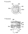
- FIG.44(b) is a cross-section of both the main electrodes 530 illustrating the above-mentioned current path.
- the current flows from the upper main electrode 530 to the lower main electrode 530 through a point Q1 on the upper main electrode and a point Q2 on the lower main electrode 537 as shown by an arrow. Consequently, a magnetic field which is perpendicular to the paper surface of FIG.44(b) and is directed from behind to before of the paper surface is generated as represented by the known right-handed screw rule.
- the arc generated between both the point Q1 and Q2 is given a moving force F in the left direction by the known left-hand rule of Fleming. Consequently, the arc is rapidly moved to the center part of the main electrodes and is diffused.
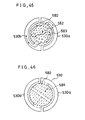
- slits 582 and 583 are formed in the good conductor 580 on the same circle in order to guide the current to a predetermined path.
- the slits 582 and 583 are formed by straight slits extended from the circumference to the center part in the radial direction, and arc-shaped slits connected to the inner ends of the straight slits. Consequently, the path the current flowing the good conductor 580 is similar to the path of the current along the coil electrodes 520a and 520b.
- the magnet field generated by the current flowing the good conductor 580 is added to the magnetic field in the axial direction by the coil parts 530a and 530b contacting the coil electrodes 520a and 520b. And thus the magnetic field in the axial direction is enhanced.
- the good conductor 580 is divided into four zones by a cross-shaped slit 584 passing through the center of the good conductor 580. Consequently, an eddy current is interrupted, and thereby harmful influence of the eddy current is significantly reduced.
- plural comb-shaped slits 585 may be formed in the good conductor 580.
- Each slit 585 is straight-shaped, and one end thereof is alternately terminated before the circumference.
- the eddy current is interrupted by the plural slits 585 and is reduced.
- the twenty-first embodiment of the vacuum interrupter corresponding to the constitution of claim 18, as shown in a plan view of the electrode assembly of FIG.48, four separate slits 586 are formed in the good conductor 580.
- the slits 586 are arranged in the radial directions and one end of each slit 586 is terminated before the center part of the good conductor 580. Consequently, the eddy current is interrupted.
- the current flows outward in the radial direction on the upper electrode, and flows inward in the radial direction on the lower electrode between both the electrodes. Consequently, a magnetic field which is perpendicular to the arc is generated, and the arc is given a moving force in the direction shown by an arrow F. The arc is rapidly moved outward in the radial direction and is diffused.
- the good conductor 580 is formed on the upper surface of the support member 508.
- the good conductor 580 may be attached on the back surface of the main electrode 530.
- the good conductor 580 may be formed on the electrode in one body.
- a high resistance member made of stainless steel for example, may be formed as replacement for the slit.
- the number of the coil parts for generating the magnetic field in the axial direction is not limited to two, and one, three, four or plural coil parts may be used.
- the configuration of the electrodes is applicable to the vacuum interrupter having a general configuration of the electrodes for generating the magnetic field in the axial direction, for example, vacuum interrupters shown in Japanese Patent No. Sho 58-28132 and the Japanese Utility Model Sho 62-45401.
- the inventions of claims 19, 20, 21, 22, 23 and 24 are directed to the vacuum interrupter of which restrike or reignition of the arc is prevented by preventing generation of a high electric field area on the surface of the main electrode in disconnection operation of both the electrodes, and thereby the withstand voltage characteristic is improved.
- the details are elucidated hereafter.
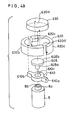
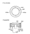
- FIG.49 is an exploded perspective assembly view of the electrode configuration of the vacuum interrupter which is a premise technology of the twenty-second embodiment corresponding to the constitution of claims 19, 20, 21, 22, 23 and 24.
- an arm-shaped connecting member 610 has a ring part 610c at the center part to be put on the boss 8a, and two arm parts 610a and 610b are extended from the ring part 610c in the radial directions.
- a coil electrode 620 composed of two arc-shaped conductors 620a and 620b are fixed on the arm-shaped connecting member 610 in a manner that the arm part 610a is connected to an end of the arc-shaped conductor 620a and the arm part 610b is connected to an end of the arc-shaped conductor 620b. Consequently, a coil current flows along the same circumference.
- salient connection parts 620c and 620d are formed on respective inside surfaces of the other ends of the arc-shaped conductors 620a and 620b of the coil electrode 620 in opposed relationship.
- a disc-shaped main electrode 630 is connected to the coil electrodes 620 through the connection parts 620c and 620d.
- a shaft 608a of a support member 608 is inserted in the support hole 8b of the electrode rod 8 and is fixed thereby, and a disc-shaped support part 608b supports the back surface of the center part 630d of the main electrode 630.
- FIG.50(a) is a plan view of the electrode assembly
- FIG.50(b) is a cross-section of the electrode assembly.
- the current flows outward from the point P of the main electrode 630 in the radial directions along current paths R.
- the current flows to the arc-shaped conductors 620a and 620b through the connection parts 620c and 620d of the coil electrode 620.
- the current flows in the electrode rod 8 through the arm parts 610a and 610b connected to the respective ends of the arc-shaped conductors 620a and 620b.
- the magnetic field in the radial direction is generated between both the main electrodes arranged in opposed relationship by the current flowing the arc-shaped conductors 620a and 620b of the coil electrode 620 along the circumference. And thus the arc voltage is reduced and diffusion of the arc is facilitated.
- the present invention is directed to the vacuum interrupter of which the gap formed by the arc-shaped parts of the coil electrode or the main electrode part is covered by a coil cover, and thereby the restrike of the arc is prevented.
- FIG.51 is an exploded perspective assembly view of the electrode configuration of the vacuum interrupter in accordance with the twenty-second embodiment
- FIG.52(a) is a plan view of the electrode
- FIG.52(b) is a cross-section of the electrode assembly.
- Elements having the same structure and function as the elements in FIGs. 49 and 50 are identified by like numerals and the elucidation is omitted.
- a cylindrical coil cover 640 covers the arc-shaped conductors 620a and 620b of the coil electrode 620 in order not to expose the arc-shaped conductors 620a and 620b in the direction opposing to the main electrode.
- the coil cover 640 is made of metal having superior withstand voltage characteristic in comparison with the material of the main electrode 630.
- the main electrode 630 is made of oxygen free copper, stainless steel (SUS), alloy of aluminum or alloy of copper is applicable to the material of the coil cover 640.
- the arc-shaped conductor of the coil electrode 620 is protected by covering the arc-shaped conductors 620a and 620b by the coil cover 640 made of material which is superior in the withstand voltage characteristic than the main electrode material. And thereby the overall withstand voltage characteristic of the electrodes can be improved.
- FIG.53(a) is a plan view of the electrode assembly in an example of the twenty-second embodiment
- FIG.33(b) is a cross-section of the electrode assembly.
- a coil cover 641 covers a gap between the arc-shaped conductors 620a and 620b of the coil electrode 620 and the main electrode 630. Consequently, the withstand voltage characteristic in the arc-shaped conductor part of the coil and the gap part is improved.
- a coil cover of a shape which fits the structure of the main electrode may be mounted.
- FIG.54(a) is an exploded perspective assembly view of the electrode assembly having a coil cover of another example in the twenty-second embodiment
- FIG.54(b) is a plan view of the electrode assembly having the coil cover
- FIG.54(c) is a side view of the electrode assembly.
- the main electrode 630 is provided with an arm parts 630(a) and 630-(b), and the surface of the main electrode 630 is protruded from the arm parts 630a and 630b.
- Ditches 642a are formed on the back surface of the coil cover 642, and the arm parts 630a and 630b are inserted in the respective ditches 642a in assembly. Consequently, gaps in the arc-shaped coil electrode 620 and in the peripheral portion of the main electrode 630 are completely covered by the coil cover 642, and a similar effect to the coil cover shown in FIGs. 53(a) and 53(b) is realizable.
- the coil covers 640, 641 and 642 are made of material which is superior in the withstand voltage characteristic than that of the main electrode 630 of the arc diffusion electrode
- the coil cover is made of material which is higher in arc voltage than that of the main electrode.
- the coil cover is made of "Cu” alloy.
- the coil cover is made of "Mo" or the like.
- the diameter of the main electrode 630 is smaller than that of the coil electrode 620. Even if the diameter of the main electrode is substantially equal to the diameter of the coil electrode as in a vacuum interrupter shown in the Japanese Patent Sho 58-26132 and the Japanese Utility Model Sho 62-45401, a similar effect is realizable.
- a main electrode 650 is composed of two disc-shaped members superimposed in the same axis. Slits 660 in the radial directions and slits 661 along the circumference are formed on the lower disc-shaped member in order to form arc-shaped coil parts 650a and 650b which correspond to arc-shaped conductors 620a and 620b of the coil electrode 620.
- the upper disc-shaped member is connected to the lower disc-shaped member by a neck part 650d (central part), and the upper disc-shaped part 650e serves as the arc diffusion electrode.
- the slit 660, the slit 661 and the arc-shaped parts 620a and 620b of the coil electrode 620 are covered by the disc-shaped part 650e of the arc diffusion electrode and are not exposed outside. Therefore, a high potential electric field does not arise in the area, and the withstand voltage characteristic is improved.
- FIG.56(a) is a cross-section of an electrode assembly
- FIG.56(b) is a plan view of the electrode assembly
- FIG.56(c) is an exploded perspective assembly view of the electrode assembly. Ditches 681 along the circumference and ditches 682 in the radial directions are formed on the back surface of the main electrode 680. In the exploded perspective assembly view of FIG.56(c), the back surface of the main electrode 680 is shown. A conductor plate 690 is attached to the back surface of the main electrode 680.
- High resistance members 691 are formed on the surface of the conductor plate 690 in the radial directions in order to compensate the magnetic field in the axial direction.
- the diameter of the conductor plate 690 is larger than the inner diameter of the ditch 681 and is smaller than the outer diameter of the ditch 681.
- the withstand voltage characteristic of the electrode is improved.
- the ditch 681 may be formed by filling with a high resistance member.
- the most current from the central part of the main electrode 680 to the coil electrode 620 flows the arm parts 683 formed between both the slits 681 and 682, and successively flows along the circumference of the coil electrode 620. Consequently, the current serves to enhance the magnetic field in the axial direction.
Landscapes
- High-Tension Arc-Extinguishing Switches Without Spraying Means (AREA)
Applications Claiming Priority (27)
| Application Number | Priority Date | Filing Date | Title |
|---|---|---|---|
| JP32609292 | 1992-11-10 | ||
| JP32609092 | 1992-11-10 | ||
| JP326090/92 | 1992-11-10 | ||
| JP32609092 | 1992-11-10 | ||
| JP326092/92 | 1992-11-10 | ||
| JP32609292 | 1992-11-10 | ||
| JP33514792 | 1992-11-19 | ||
| JP33514692 | 1992-11-19 | ||
| JP335147/92 | 1992-11-19 | ||
| JP33514792 | 1992-11-19 | ||
| JP33514692 | 1992-11-19 | ||
| JP335146/92 | 1992-11-19 | ||
| JP16542993 | 1993-07-05 | ||
| JP165430/93 | 1993-07-05 | ||
| JP16543093 | 1993-07-05 | ||
| JP16543093 | 1993-07-05 | ||
| JP16542993 | 1993-07-05 | ||
| JP165429/93 | 1993-07-05 | ||
| JP18130093 | 1993-07-22 | ||
| JP18130193 | 1993-07-22 | ||
| JP181301/93 | 1993-07-22 | ||
| JP18130093 | 1993-07-22 | ||
| JP181300/93 | 1993-07-22 | ||
| JP18130193 | 1993-07-22 | ||
| JP271959/93 | 1993-10-29 | ||
| JP5271959A JP2861757B2 (ja) | 1992-11-10 | 1993-10-29 | 真空バルブの電極装置 |
| JP27195993 | 1993-10-29 |
Publications (3)
| Publication Number | Publication Date |
|---|---|
| EP0597434A2 true EP0597434A2 (de) | 1994-05-18 |
| EP0597434A3 EP0597434A3 (de) | 1995-02-08 |
| EP0597434B1 EP0597434B1 (de) | 2001-03-07 |
Family
ID=27577504
Family Applications (1)
| Application Number | Title | Priority Date | Filing Date |
|---|---|---|---|
| EP93118102A Expired - Lifetime EP0597434B1 (de) | 1992-11-10 | 1993-11-08 | Vakuumschalter |
Country Status (5)
| Country | Link |
|---|---|
| US (3) | US5495085A (de) |
| EP (1) | EP0597434B1 (de) |
| JP (1) | JP2861757B2 (de) |
| DE (1) | DE69329987T2 (de) |
| PT (1) | PT597434E (de) |
Cited By (8)
| Publication number | Priority date | Publication date | Assignee | Title |
|---|---|---|---|---|
| EP0715324A1 (de) | 1994-11-29 | 1996-06-05 | Schneider Electric Sa | Elektrischer Vakuumschalter |
| DE4446672A1 (de) * | 1994-12-15 | 1996-09-12 | Slamecka Ernst | Vakuumschalter-Kontaktanordnung |
| DE19957228A1 (de) * | 1999-11-27 | 2001-05-31 | Moeller Gmbh | Kontaktanordnung für eine Vakuumschaltkammer |
| US7362404B2 (en) | 2004-03-31 | 2008-04-22 | Fujitsu Limited | Liquid crystal display device and method of manufacturing liquid crystal display device for preventing defects in liquid crystal |
| WO2013175112A1 (fr) * | 2012-05-24 | 2013-11-28 | Schneider Electric Industries Sas | Dispositif de contrôle d'arc pour ampoule a vide |
| DE102012221844A1 (de) * | 2012-11-29 | 2014-06-05 | Siemens Aktiengesellschaft | Schaltkontakt für Vakuumschaltröhren |
| CN104282494A (zh) * | 2013-07-12 | 2015-01-14 | 富士电机机器制御株式会社 | 接点装置和使用它的电磁接触器 |
| CN109308976A (zh) * | 2018-11-07 | 2019-02-05 | 平高集团有限公司 | 线圈式纵向磁场触头组件及真空灭弧室 |
Families Citing this family (27)
| Publication number | Priority date | Publication date | Assignee | Title |
|---|---|---|---|---|
| JP2861757B2 (ja) * | 1992-11-10 | 1999-02-24 | 三菱電機株式会社 | 真空バルブの電極装置 |
| TW265452B (de) * | 1994-04-11 | 1995-12-11 | Hitachi Seisakusyo Kk | |
| JP3462367B2 (ja) * | 1997-06-27 | 2003-11-05 | 株式会社日立製作所 | 複合絶縁開閉装置 |
| GB2341004B (en) * | 1998-08-21 | 2002-07-17 | Alstom Uk Ltd | Improvements in vacuum interrupters |
| DE10065091A1 (de) * | 2000-12-21 | 2002-06-27 | Siemens Ag | Kontaktanordnung für eine Vakuumschaltröhre |
| JP4667032B2 (ja) * | 2004-12-10 | 2011-04-06 | 三菱電機株式会社 | 真空バルブ |
| FR2903221B1 (fr) * | 2006-06-30 | 2013-12-20 | Schneider Electric Ind Sas | Procede de fixation d'un element dans un appareil electrique et appareil electrique tel une ampoule a vide comportant au moins deux parties fixees suivant un tel procede |
| KR101261967B1 (ko) * | 2009-03-11 | 2013-05-08 | 엘에스산전 주식회사 | 진공인터럽터의 전극 |
| FR2946792A1 (fr) * | 2009-06-10 | 2010-12-17 | Areva T & D Sa | Enroulement pour contact d'ampoule a vide a moyenne tension a endurance amelioree, ampoule a vide et disjoncteur, tel qu'un disjoncteur sectionneur d'alternateur associes. |
| FR2946791B1 (fr) * | 2009-06-10 | 2011-09-23 | Areva T & D Sa | Contact pour ampoule a vide a moyenne tension a structure renforcee, ampoule a vide et disjoncteur, tel qu'un disjoncteur sectionneur d'alternateur associes. |
| FR2946790B1 (fr) * | 2009-06-10 | 2011-07-01 | Areva T & D Sa | Contact pour ampoule a vide a moyenne tension a coupure d'arc amelioree, ampoule a vide et disjoncteur, tel qu'un disjoncteur sectionneur d'alternateur associes. |
| JP5350317B2 (ja) * | 2009-09-30 | 2013-11-27 | 株式会社日立製作所 | 真空開閉器、または開閉器用の電極もしくは真空開閉器の製造方法 |
| JP2011242879A (ja) * | 2010-05-14 | 2011-12-01 | Panasonic Corp | 接続装置 |
| KR20130000677A (ko) * | 2011-06-23 | 2013-01-03 | 엘에스산전 주식회사 | 진공 인터럽터의 전극 조립체 |
| CN102522259B (zh) * | 2011-12-09 | 2015-07-15 | 沈阳工业大学 | 盘型叠式旋磁纵吹真空灭弧室 |
| CN102522257B (zh) * | 2011-12-09 | 2015-07-15 | 沈阳工业大学 | 盘式旋磁纵吹真空灭弧室 |
| CN105027248B (zh) * | 2013-03-05 | 2016-08-24 | 三菱电机株式会社 | 真空阀 |
| US9006600B2 (en) | 2013-06-14 | 2015-04-14 | Eaton Corporation | High current vacuum interrupter with sectional electrode and multi heat pipes |
| US9373468B2 (en) * | 2014-09-16 | 2016-06-21 | Tyco Electronics Corporation | Arc control for contactor assembly |
| CN104269319B (zh) * | 2014-10-15 | 2016-12-07 | 国网浙江临海市供电公司 | 一种带有防扭真空灭弧室的断路器 |
| US9640353B2 (en) * | 2014-10-21 | 2017-05-02 | Thomas & Betts International Llc | Axial magnetic field coil for vacuum interrupter |
| CN109494116B (zh) * | 2018-11-07 | 2020-10-13 | 平高集团有限公司 | 一种线圈式纵向磁场触头组件及真空灭弧室 |
| JP7109659B2 (ja) * | 2019-04-23 | 2022-07-29 | 三菱電機株式会社 | 真空バルブ |
| CN110853975B (zh) * | 2019-11-27 | 2021-11-02 | 云南电网有限责任公司电力科学研究院 | 一种碟式触头 |
| EP4160642A4 (de) | 2020-05-28 | 2023-07-05 | Mitsubishi Electric Corporation | Vakuumventil |
| JP7499969B2 (ja) * | 2021-06-29 | 2024-06-14 | 三菱電機株式会社 | 真空バルブ |
| JP7548264B2 (ja) * | 2022-03-30 | 2024-09-10 | 三菱電機株式会社 | 真空バルブ |
Family Cites Families (44)
| Publication number | Priority date | Publication date | Assignee | Title |
|---|---|---|---|---|
| US3089936A (en) * | 1960-02-23 | 1963-05-14 | Gen Electric | Contact structure for an electric circuit interrupter |
| US3405300A (en) * | 1965-07-07 | 1968-10-08 | Matsushita Electric Industrial Co Ltd | Gas filled coaxial type electric switch with magnetic field cut-off |
| FR1491235A (fr) * | 1966-02-22 | 1967-08-11 | Comp Generale Electricite | Générateur de choc |
| US3522399A (en) * | 1968-03-08 | 1970-07-28 | Gen Electric | Vacuum-type circuit interrupter with contacts having particularly shaped circumferentially spaced slots |
| US3811070A (en) * | 1972-10-25 | 1974-05-14 | Westinghouse Electric Corp | Laser initiated three electrode type triggered vacuum gap device |
| JPS5422813B2 (de) * | 1973-09-10 | 1979-08-09 | ||
| FR2279216A1 (fr) * | 1973-09-10 | 1976-02-13 | Tokyo Shibaura Electric Co | Interrupteur a vide a champ magnetique |
| US3980850A (en) * | 1974-12-19 | 1976-09-14 | Westinghouse Electric Corporation | Vacuum interrupter with cup-shaped contact having an inner arc controlling electrode |
| US4152625A (en) * | 1978-05-08 | 1979-05-01 | The United States Of America As Represented By The Secretary Of The Army | Plasma generation and confinement with continuous wave lasers |
| JPS5826132B2 (ja) * | 1978-11-22 | 1983-06-01 | 株式会社日立製作所 | 真空しや断器 |
| JPS5847627Y2 (ja) * | 1979-06-27 | 1983-10-31 | 株式会社明電舎 | 真空しや断器 |
| JPS5624722A (en) * | 1979-08-01 | 1981-03-09 | Tokyo Shibaura Electric Co | Vacuum breaker |
| JPS55159524A (en) * | 1980-06-02 | 1980-12-11 | Tokyo Shibaura Electric Co | Vacuum breaker |
| JPS5776713A (en) * | 1980-10-30 | 1982-05-13 | Tokyo Shibaura Electric Co | Vacuum valve |
| JPS57191922A (en) * | 1981-05-21 | 1982-11-25 | Meidensha Electric Mfg Co Ltd | Vacuum breaker |
| JPS57192637U (de) * | 1981-05-30 | 1982-12-07 | ||
| JPS57212719A (en) * | 1981-06-24 | 1982-12-27 | Hitachi Ltd | Vacuum breaker |
| DE3133799A1 (de) * | 1981-08-26 | 1983-03-17 | Siemens AG, 1000 Berlin und 8000 München | "kontaktanordnung fuer vakuumschalter" |
| US4512867A (en) * | 1981-11-24 | 1985-04-23 | Andreev Anatoly A | Method and apparatus for controlling plasma generation in vapor deposition |
| JPS58100325A (ja) * | 1981-12-09 | 1983-06-15 | 三菱電機株式会社 | 真空しや断器 |
| US4588879A (en) * | 1982-11-30 | 1986-05-13 | Kabushika Kaisha Meidensha | Vacuum interrupter |
| JPS59101732A (ja) * | 1982-12-01 | 1984-06-12 | 株式会社明電舎 | 真空インタラプタの電極 |
| JPS59114716A (ja) * | 1982-12-21 | 1984-07-02 | 株式会社東芝 | 真空バルブ |
| JPS59169013A (ja) * | 1983-03-15 | 1984-09-22 | 株式会社明電舎 | 真空インタラプタ |
| CA1236868A (en) * | 1983-03-15 | 1988-05-17 | Yoshiyuki Kashiwagi | Vacuum interrupter |
| JPS6051851U (ja) * | 1983-09-17 | 1985-04-11 | 株式会社東芝 | 真空バルブ |
| US4553002A (en) * | 1983-12-05 | 1985-11-12 | Westinghouse Electric Corp. | Axial magnetic field vacuum-type circuit interrupter |
| DE3415743A1 (de) * | 1984-04-26 | 1985-10-31 | Siemens AG, 1000 Berlin und 8000 München | Kontaktanordnung fuer einen vakuumschalter |
| JPS61195528A (ja) * | 1985-02-22 | 1986-08-29 | 三菱電機株式会社 | 真空しや断器の電極構造 |
| DE3510981A1 (de) * | 1985-03-22 | 1985-10-31 | Ernst Prof. Dr.techn.habil. 1000 Berlin Slamecka | Vakuumschalter - erregerkontaktanordnung |
| GB8510441D0 (en) * | 1985-04-24 | 1985-05-30 | Vacuum Interrupters Ltd | High current switch contacts |
| JPS6217054U (de) * | 1985-07-17 | 1987-01-31 | ||
| JPS6231917A (ja) * | 1985-08-02 | 1987-02-10 | 三菱電機株式会社 | 真空放電応用機器の電極構造 |
| DE3610245A1 (de) * | 1986-03-26 | 1987-10-01 | Siemens Ag | Kontaktanordnung fuer vakuumschalter mit axialem magnetfeld und verfahren zur herstellung der zugehoerigen kontaktstuecke |
| JPH01502546A (ja) * | 1986-03-26 | 1989-08-31 | シーメンス、アクチエンゲゼルシヤフト | 軸方向磁界を伴なう真空遮断器の接触子装置 |
| JPH0619938B2 (ja) * | 1987-03-10 | 1994-03-16 | 三菱電機株式会社 | 真空開閉装置 |
| SE461761B (sv) * | 1988-05-03 | 1990-03-19 | Fiz Tekh Inst Ioffe | Elektrisk ljusbaaganordning |
| US4978893A (en) * | 1988-09-27 | 1990-12-18 | The United States Of American As Epresented By The United States The Department Of Energy | Laser-triggered vacuum switch |
| JPH02270233A (ja) * | 1989-04-10 | 1990-11-05 | Toshiba Corp | 真空バルブ |
| DE3915287C2 (de) * | 1989-05-10 | 1997-12-18 | Sachsenwerk Ag | Kontaktanordnung für einen Vakuumschalter |
| JPH03272530A (ja) * | 1990-03-20 | 1991-12-04 | Fuji Electric Co Ltd | 真空遮断器用真空バルブ |
| DE4013903A1 (de) * | 1990-04-25 | 1990-11-22 | Slamecka Ernst | Magnetfeld-kontaktanordnung fuer vakuumschalter |
| JPH05190062A (ja) * | 1992-01-16 | 1993-07-30 | Hitachi Ltd | 真空遮断器用電極 |
| JP2861757B2 (ja) * | 1992-11-10 | 1999-02-24 | 三菱電機株式会社 | 真空バルブの電極装置 |
-
1993
- 1993-10-29 JP JP5271959A patent/JP2861757B2/ja not_active Expired - Fee Related
- 1993-11-04 US US08/145,743 patent/US5495085A/en not_active Expired - Lifetime
- 1993-11-08 DE DE69329987T patent/DE69329987T2/de not_active Expired - Fee Related
- 1993-11-08 PT PT93118102T patent/PT597434E/pt unknown
- 1993-11-08 EP EP93118102A patent/EP0597434B1/de not_active Expired - Lifetime
-
1995
- 1995-06-07 US US08/478,392 patent/US5646386A/en not_active Expired - Fee Related
- 1995-06-07 US US08/475,333 patent/US5597993A/en not_active Expired - Fee Related
Cited By (14)
| Publication number | Priority date | Publication date | Assignee | Title |
|---|---|---|---|---|
| EP0715324A1 (de) | 1994-11-29 | 1996-06-05 | Schneider Electric Sa | Elektrischer Vakuumschalter |
| DE4446672A1 (de) * | 1994-12-15 | 1996-09-12 | Slamecka Ernst | Vakuumschalter-Kontaktanordnung |
| DE19957228A1 (de) * | 1999-11-27 | 2001-05-31 | Moeller Gmbh | Kontaktanordnung für eine Vakuumschaltkammer |
| WO2001041173A1 (de) * | 1999-11-27 | 2001-06-07 | Moeller Gmbh | Kontaktanordnung für eine vakuumschaltkammer |
| DE19957228B4 (de) * | 1999-11-27 | 2009-04-23 | Moeller Gmbh | Kontaktanordnung für eine Vakuumschaltkammer |
| US7362404B2 (en) | 2004-03-31 | 2008-04-22 | Fujitsu Limited | Liquid crystal display device and method of manufacturing liquid crystal display device for preventing defects in liquid crystal |
| WO2013175112A1 (fr) * | 2012-05-24 | 2013-11-28 | Schneider Electric Industries Sas | Dispositif de contrôle d'arc pour ampoule a vide |
| FR2991097A1 (fr) * | 2012-05-24 | 2013-11-29 | Schneider Electric Ind Sas | Dispositif de controle d'arc pour ampoule a vide |
| US9460874B2 (en) | 2012-05-24 | 2016-10-04 | Schneider Electric Industries Sas | Arc control device for vacuum bulb |
| RU2667091C2 (ru) * | 2012-05-24 | 2018-09-14 | Шнейдер Электрик Эндюстри Сас | Устройство регулирования дуги для вакуумного прерывателя |
| DE102012221844A1 (de) * | 2012-11-29 | 2014-06-05 | Siemens Aktiengesellschaft | Schaltkontakt für Vakuumschaltröhren |
| CN104282494A (zh) * | 2013-07-12 | 2015-01-14 | 富士电机机器制御株式会社 | 接点装置和使用它的电磁接触器 |
| CN104282494B (zh) * | 2013-07-12 | 2017-04-12 | 富士电机机器制御株式会社 | 接点装置和使用它的电磁接触器 |
| CN109308976A (zh) * | 2018-11-07 | 2019-02-05 | 平高集团有限公司 | 线圈式纵向磁场触头组件及真空灭弧室 |
Also Published As
| Publication number | Publication date |
|---|---|
| JPH0785754A (ja) | 1995-03-31 |
| EP0597434B1 (de) | 2001-03-07 |
| DE69329987D1 (de) | 2001-04-12 |
| US5597993A (en) | 1997-01-28 |
| JP2861757B2 (ja) | 1999-02-24 |
| EP0597434A3 (de) | 1995-02-08 |
| US5495085A (en) | 1996-02-27 |
| DE69329987T2 (de) | 2001-10-25 |
| PT597434E (pt) | 2001-07-31 |
| US5646386A (en) | 1997-07-08 |
Similar Documents
| Publication | Publication Date | Title |
|---|---|---|
| EP0597434A2 (de) | Vakuumschalter | |
| CA1118475A (en) | Vacuum-type circuit interrupter with an improved contact with axial magnetic field coil | |
| EP0329410B1 (de) | Vakuumschalter | |
| EP0349303B1 (de) | Vakuumschalter | |
| US4704506A (en) | Vacuum interrupter | |
| US4473731A (en) | Vacuum circuit interrupter | |
| US4117288A (en) | Vacuum type circuit interrupter with a contact having integral axial magnetic field means | |
| CA1224233A (en) | Vacuum interrupter | |
| JPH0322007B2 (de) | ||
| KR20020030165A (ko) | 종자계 방식 진공인터럽터용 전극구조 | |
| KR930011829B1 (ko) | 진공 차단기 | |
| JPH04349320A (ja) | 真空切換え室 | |
| KR860001452B1 (ko) | 진공 차단기 | |
| EP0133368B2 (de) | Kontakt für Hochstromschalter | |
| US6426475B2 (en) | Vacuum valve | |
| EP0185211B2 (de) | Vakuumschalter | |
| CA1068754A (en) | Compact high-current vacuum circuit interrupter comprising a metal housing that is electrically connected to one contact of the interrupter | |
| US4737605A (en) | Vacuum switching tube | |
| GB2061010A (en) | Vacuum type circuit interrupter | |
| KR0150016B1 (ko) | 진공스위치관 | |
| CA1319730C (en) | Vacuum-type circuit interrupter | |
| WO1987003136A1 (en) | Vacuum interrupter | |
| JPH02270233A (ja) | 真空バルブ | |
| JPH05325739A (ja) | 開閉装置の電極構造 | |
| US4386249A (en) | Vacuum circuit interrupter with auxiliary contact for plural arc path device with arc rotating means associated with the primary and auxiliary contacts |
Legal Events
| Date | Code | Title | Description |
|---|---|---|---|
| PUAI | Public reference made under article 153(3) epc to a published international application that has entered the european phase |
Free format text: ORIGINAL CODE: 0009012 |
|
| AK | Designated contracting states |
Kind code of ref document: A2 Designated state(s): DE GB PT |
|
| PUAL | Search report despatched |
Free format text: ORIGINAL CODE: 0009013 |
|
| AK | Designated contracting states |
Kind code of ref document: A3 Designated state(s): DE GB PT |
|
| 17P | Request for examination filed |
Effective date: 19950614 |
|
| 17Q | First examination report despatched |
Effective date: 19980701 |
|
| GRAG | Despatch of communication of intention to grant |
Free format text: ORIGINAL CODE: EPIDOS AGRA |
|
| GRAG | Despatch of communication of intention to grant |
Free format text: ORIGINAL CODE: EPIDOS AGRA |
|
| GRAG | Despatch of communication of intention to grant |
Free format text: ORIGINAL CODE: EPIDOS AGRA |
|
| GRAH | Despatch of communication of intention to grant a patent |
Free format text: ORIGINAL CODE: EPIDOS IGRA |
|
| GRAH | Despatch of communication of intention to grant a patent |
Free format text: ORIGINAL CODE: EPIDOS IGRA |
|
| GRAA | (expected) grant |
Free format text: ORIGINAL CODE: 0009210 |
|
| AK | Designated contracting states |
Kind code of ref document: B1 Designated state(s): DE GB PT |
|
| REF | Corresponds to: |
Ref document number: 69329987 Country of ref document: DE Date of ref document: 20010412 |
|
| REG | Reference to a national code |
Ref country code: GB Ref legal event code: 727 |
|
| REG | Reference to a national code |
Ref country code: GB Ref legal event code: 727A |
|
| REG | Reference to a national code |
Ref country code: PT Ref legal event code: SC4A Free format text: AVAILABILITY OF NATIONAL TRANSLATION Effective date: 20010411 |
|
| EN | Fr: translation not filed | ||
| REG | Reference to a national code |
Ref country code: GB Ref legal event code: 727B |
|
| REG | Reference to a national code |
Ref country code: GB Ref legal event code: IF02 |
|
| PLBE | No opposition filed within time limit |
Free format text: ORIGINAL CODE: 0009261 |
|
| STAA | Information on the status of an ep patent application or granted ep patent |
Free format text: STATUS: NO OPPOSITION FILED WITHIN TIME LIMIT |
|
| 26N | No opposition filed | ||
| PGFP | Annual fee paid to national office [announced via postgrant information from national office to epo] |
Ref country code: DE Payment date: 20061102 Year of fee payment: 14 |
|
| PGFP | Annual fee paid to national office [announced via postgrant information from national office to epo] |
Ref country code: PT Payment date: 20061107 Year of fee payment: 14 |
|
| PGFP | Annual fee paid to national office [announced via postgrant information from national office to epo] |
Ref country code: GB Payment date: 20061108 Year of fee payment: 14 |
|
| REG | Reference to a national code |
Ref country code: PT Ref legal event code: MM4A Free format text: LAPSE DUE TO NON-PAYMENT OF FEES Effective date: 20080508 |
|
| GBPC | Gb: european patent ceased through non-payment of renewal fee |
Effective date: 20071108 |
|
| PG25 | Lapsed in a contracting state [announced via postgrant information from national office to epo] |
Ref country code: PT Free format text: LAPSE BECAUSE OF NON-PAYMENT OF DUE FEES Effective date: 20080508 |
|
| PG25 | Lapsed in a contracting state [announced via postgrant information from national office to epo] |
Ref country code: DE Free format text: LAPSE BECAUSE OF NON-PAYMENT OF DUE FEES Effective date: 20080603 |
|
| PG25 | Lapsed in a contracting state [announced via postgrant information from national office to epo] |
Ref country code: GB Free format text: LAPSE BECAUSE OF NON-PAYMENT OF DUE FEES Effective date: 20071108 |