EP0597564B1 - Sprinkler mit Druckanzeige-vorrichtung - Google Patents
Sprinkler mit Druckanzeige-vorrichtung Download PDFInfo
- Publication number
- EP0597564B1 EP0597564B1 EP93250314A EP93250314A EP0597564B1 EP 0597564 B1 EP0597564 B1 EP 0597564B1 EP 93250314 A EP93250314 A EP 93250314A EP 93250314 A EP93250314 A EP 93250314A EP 0597564 B1 EP0597564 B1 EP 0597564B1
- Authority
- EP
- European Patent Office
- Prior art keywords
- hole
- movable rod
- sprinkler head
- sprinkler
- plug
- Prior art date
- Legal status (The legal status is an assumption and is not a legal conclusion. Google has not performed a legal analysis and makes no representation as to the accuracy of the status listed.)
- Expired - Lifetime
Links
Images



Classifications
-
- A—HUMAN NECESSITIES
- A62—LIFE-SAVING; FIRE-FIGHTING
- A62C—FIRE-FIGHTING
- A62C31/00—Delivery of fire-extinguishing material
- A62C31/28—Accessories for delivery devices, e.g. supports
-
- A—HUMAN NECESSITIES
- A62—LIFE-SAVING; FIRE-FIGHTING
- A62C—FIRE-FIGHTING
- A62C37/00—Control of fire-fighting equipment
- A62C37/50—Testing or indicating devices for determining the state of readiness of the equipment
-
- A—HUMAN NECESSITIES
- A62—LIFE-SAVING; FIRE-FIGHTING
- A62C—FIRE-FIGHTING
- A62C31/00—Delivery of fire-extinguishing material
- A62C31/005—Delivery of fire-extinguishing material using nozzles
-
- A—HUMAN NECESSITIES
- A62—LIFE-SAVING; FIRE-FIGHTING
- A62C—FIRE-FIGHTING
- A62C31/00—Delivery of fire-extinguishing material
- A62C31/02—Nozzles specially adapted for fire-extinguishing
Definitions
- This invention relates to a sprinkler head having a checking means for checking that fluid has been filled inside of the sprinkler head body and a method for checking that the fluid has been filled using such sprinkler head.
- the sprinkler head described therein is characterized in that a plug is pushed upwardly and is maintained at a position so as to close an outlet port of a head frame.
- the sprinkler head of this arrangement is generally mounted on a ceiling plane of a room or the like in a state where fire protection water is filled inside of the head frame such that the sprinker head can sprinkle the fire protection water once fire has occurred.
- EP-0 183 263, GB-2 084 014, GB - 722 837 and FR-2 513 523 disclose fire extinguishing devices comprising a container with fire extinguisher and an outlet that is directly mounted to said containers. Systems are disclosed wherein a movable rod is incorporated in the wall of the container or in an outlet valve to indicate the level and/or pressure of fire extinguisher present in the container.
- WO-81/02484 discloses further a device for detecting leaks in piping systems that uses also a movable rod. Devices of this kind only indicate that there is no leak; they do not indicate that e. g. extinguishing fluid is present in each sprinkler head.
- a sprinkler system consisting of a system of pipes connected to a supply of fire extinguishing fluid, said sprinkler system being connected with a plurality of sprinkler heads projecting into the room, each comprising a plug that automatically opens an outlet port of the sprinkler head when a specific temperature is reached, characterized in that each sprinkler head includes a checking means that visually indicates the presence of fire extinguishing fluid at said plug, said checking means having the form of an outwardly threaded portion screwed into a through-hole of said plug and a rod movable in axial direction inside a through-hole of said sprinkler head which, when in communication with fire extinguishing fluid, can be moved forward or backward into a specific indicating position, or said checking means having the form of a valve located in a through-hole which can be operated to trigger the dripping out of fire extinguishing fluid.
- a method for checking the proper connection of sprinkler heads or distribution pipes and for locating interruptions in the piping of such a sprinkler system characterized in that the change in position of a checking means having the form of a movable rod and associated with each sprinkler head is observed, or that a dripping test is carried out by operating a valve using a movable rod.
- the filled state of the fluid inside each sprinkler head body can readily be checked from the outside.
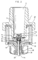
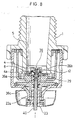
- FIG. 1 illustrates the first embodiment of the present invention.
- a head frame 1 is provided therein with a passageway 2 for fire protection water.
- a frame 3, having a substantially cylindrical shape, is threaded into an annular concaved portion of the head frame 1.
- a plug 4 is provided on its lower periphery with a collar portion 6, and is arranged inside of a sprinkler head body 27 so as to close an outlet port 5 defined in a lower portion of the head frame 1.
- a through-hole 8 is defined substantially in the center of the plug 4.
- Internal threads 7 are formed on an internal periphery of a lower portion of the through-hole 8.
- a diameter of the upper end of the through-hole 8 is smaller than that of the other portion of the through-hole 8.
- An outwardly threaded portion 9 is threaded into the internal threads 7.
- a through-hole 10 with its lower portion of hexagonal shape is defined substantially in the center of the outwardly threaded portion 9 and is associated with the through-hole 8 in fluid communication with each other.
- a sealing means (not shown) is applied between the outwardly threaded portion 9 and the internal threads 7 of the plug 4.
- a spring member 14 consisting of a belleville spring coated with fluoroplastic, is provided between a lower end of the outlet port 5 of the head frame 1 and an upper surface of the collar portion 6 of the plug 4, and is urged by a predetermined pressure.
- An inner periphery of the spring member 14 is fit in an internally extending annular groove 6a which is defined in the collar portion 6 of the plug 4.
- a plurality of deflectors 15, each of which having a bent portion, are connected to an outer periphery of the plug 4.
- a guide ring 16 having a guide member 16a which is vertically oriented and slidably abuts against an outer surface of the head frame 1, is connected to an upper end of the deflectors 15 so as to serve as a guide when the plug 4 falls down.
- a detent member 17 is formed in a partially cutaway ring-shape, and is elastically deformable so as to diametrally expand and contract.
- a pair of restraining members 18, 19 are arranged so as to restrain the decent member 17.
- a hole 18a is defined in an upper surface of the upper restraining member 18 such that a lower portion of the outernally threaded portion 9 can be inserted into that hole 18a.
- a cylindrical portion 18b of the upper restraining member 18 is provided on its inner periphery with internal threads 18c, and is slidably inserted into a cylindrical portion 19a of the lower restraining member 19.
- An upwardly sloped surface 20 and a downwardly sloped surface 21 are respectively defined on the restraining members 18, 19.
- the sloped surfaces 20, 21 come closer to each other as they advance inwardly so as to hold the detent member 17 in tensioned state.
- the detent member 17 is held between the sloped surfaces 20, 21, and an inner periphery of an inwardly projecting portion 22 defined on an inner periphery of the lower portion of the head frame 1.
- a lock screw 23 is threaded into the internal threads 18c of the upper restraining member 18.
- a through-hole 23a is defined coaxially in a center portion of the lock screw 23.
- On a lower surface of the lower restraining member 19 is provided a thermal insulating packing 24, on which a thermal sensitive member 25 is provided.
- a heat meltable member 26 is provided between the thermal sensitive member 25 and an outwardly extending flange 23b formed on a lower end of the lock screw 23 in heat conductive relationship with the thermal sensitive member 25.
- a movable rod 11 has a rod-shaped projection 11a on its upper end, a pin 11b on its lower end, and is inserted into a bore of the outernally threaded portion 9 via an elastic member 12 consisting of a coil spring so as to be moved backward and forward.
- the movable rod 11 is usually urged in an upward direction by the elastic member 12 such that a lower end of the pin 11b becomes flush with a lower surface of the lock screw 23 which defines some region of a lower surface of the sprinkler head 27, as illustrated in FIG. 1.
- On a side periphery of the pin 11b closer to the lower end thereof is applied fluorescent paint.
- An O-ring 13 seal is mounted to an outer periphery of the movable rod 11 for sealing between an inner periphery of the outernally threaded portion 9 and an outer periphery of the movable rod 11.
- the sprinkler head is fixed at a predetermined position on a ceiling plane.
- the sprinkler head is connected with a distributing water pipe (not shown) through a connecting pipe (not shown).
- the fire protection water is communicated with the distributing water pipe.
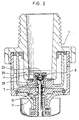
- the movable rod 11 is moved downwardly by the pressure of the fire protection water applied thereover, while resisting the spring force of the elastic member 12, and consequently the pin 11b protrudes outwardly away from the lower surface of the lock screw 23 (fig. 2).
- the pin 11b of the movable rod 11 does not protrude sufficiently or it does not protrude at all to the outside (fig 1).
- the filled state of the fire protection water inside of the sprinkler head body can be checked by observing a position of the pin 11b in this manner.
- the fluorescent paint is applied over the side periphery of the lower end of the pin 11b the position of the pin 11b can be observed at night or the like.
- the sprinkler head with such a simple construction can be manufactured readily in a cheap manner.
- the heat meltable member 26 is melted or softened, and the lower restraining member 19 moves downwardly. Then, the detent member 17 is contracted inwardly, and is released from the locking relationship with the inwardly projecting portion 22 of the frame 3.
- the upper restraining member 18, the outernally threaded portion 9 and the plug 4 fall down to the lower direction of the head frame 1 by the spring force of the spring member 14. Consequently, the fire protection water is flashed from the outlet port which has been opened, collides against an upper surface of the plug 4, and is sprinkled radially.
- the pin 11b generally becomes flush with the lower surface of the lock screw 23 by urging the movable rod 11 with the elastic member 12.
- the whole length of the pin 11b can be positioned inside of the lock screw.
- a relatively short length thereof can be positioned outside of the lock screw 23. It is essential that the filled state of the fluid such as the fire protection water inside of the sprinkler head body 27 can be checked by arranging the movable rod 11 so as to protrude to the outside after the fluid has been filled inside of the sprinkler head body 27.
- the present invention is not limited to the sprinkler head of the above embodiment. It can be applied to a sprinkler head as illustrated in FIG. 3, in which a flexible bellows 28 with a bottom wall disposed on a lower end thereof is mounted in the through-hole 8 of the plug 4 and abuts against the upper end of the movable rod 11, and a covering member having a through-hole 29, is threaded into the internal threads 7 of the through-hole 8. Further, it can be applied to a dry sprinkler head where gas such as air is filled inside of the sprinkler head body 27.
- the movable rod 11 is introduced into the sprinkler head body 27.
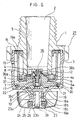
- the movable rod 11 is provided on its upper end with a movable member 31 which is slidably inserted into the through-hole 10 of the outwardly threaded portion 9.
- the movable rod 11 is usually tensioned downwardly as a usual state with the elastic member 12 of the coil spring, and the lower end of the movable rod 11 protrudes outwardly away from the lower surface of the lock screw 23.
- the lower end surface of the movable rod 11 is painted with the fluorescent paint (not shown).
- a passageway 32 is coaxially defined in a center of the movable member 31.
- a lower end of the passageway 32 is divided into several passageways, each of which extends in a radial direction.
- the divided passageways are associated with and in fluid communication with a space 34 defined by an inner periphery of the through-hole 10 of the outernally threaded portion 9 and a stepped portion 33 of the movable member 31.
- a ring seal 35 of X-shape in cross section is mounted between the outwardly threaded portion 9 and the movable member 31.
- a lower surface 33a of the stepped portion 33 of the movable member 31 is larger than an upper surface 11c of the movable rod 11.
- the movable rod 11 does not move inwardly, and a partially protruded portion of which is maintained in an initial position (fig. 4).
- the unfilled state of the fire protection water can be readily checked by observing such position of the movable rod 11 from the outside, and subsequently the insufficient connecting of the pipes or other accidents in communicating the fluid can be found before the fire occurs.
- the arrangement of this embodiment can be applied to the dry sprinkler head, in which gas such as air is filled inside of the head frame 1.
- the filled state of the fire protection water inside of the sprinkler head body 27 can be checked by observing the motion of the movable rod 11 from the outside.
- the filled state can be checked by a different means described in the fourth embodiment.
- the main features of the sprinkler head is also same as that of the first embodiment. Therefore, only different features between the embodiment, will be described hereinbelow.
- a valve 36 includes a diametrically small portion defined on its lower end which is inserted into the through-hole 10 of the outwardly threaded portion 9, a valve body 36c having a diametrically large valve seat 36a defined on an upper end of the valve 36 and an elastic member 12 in the form of a conical coil spring which is mounted above the valve seat 36a.
- valve body 36c is pressed downwardly by the elastic member 12, causing the pressure applied over the valve seat 36a and the stepped portion defined in the through-hole 10 of the outwardly threaded portion 9 via the O-ring 37, then closing the through-hole 10.
- a pin 36b is provided on an upper surface of the valve seat 36a, and is inserted into a diametrally small portion defined in an upper end of the through-hole 8 of the plug 4.
- a length of the pin 36b is determined such that an upper end thereof protrudes slightly and upwardly away from the upper surface of the plug 4 by a relatively short length, when the valve body 36c is pressed upwardly, while resisting the spring force of the elastic member 12.
- a sealing means is applied to a lower surface of the valve seat 36a.
- An outer diameter of each of the lower ends of the valve body 36c and the pin 36b is slightly smaller than an inner diameter of the through-hole 10.
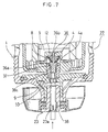
- a pushing rod 38 of a suitable length is inserted into the through-hole 23a of the lock screw 23 to push a lower surface of the valve body 36c, while resisting the spring force of the elastic member 12 (fig. 7).
- the valve body 36c is moved upwardly such that a sealing condition between the valve seat 36a and the outwardly threaded portion 9 is released.
- a relatively small amount of the fire protection water drops out of the through-hole 23a of the lock screw 23 via the outlet port 5 of the sprinkler head body 27, the through-hole 8 of the plug 4 and the through-hole 10 of the outwardly threaded portion 9.
- the pin 36b of the valve body 36c protrudes away from the through-hole 8 of the plug 4 by pressing the valve body 36c. Thereby, even if undesirable foreign materials such as a rubbish of a particular size are accumulated on the through-hole 8, they can be removed from the through-hole 8 by the motion of the pin 36b.
- the pushing rod 38 is pulled out of the through-hole 23a of the lock screw 23 to release the pressure applied over the valve body 36c, and subsequently return the valve body 36c to an initial position by a restoring force of the elastic member 12.
- the through-hole, 10 of the outwardly threaded portion 9 is closed to stop the dropping of the fire protection water.
- a seal for indicating that the filled state of the water has been tested, is bonded onto the through-hole 23a, which simultaneously serves to close the through-hole 23a.
- the filled state of the fire protection water inside of the sprinkler head body 27 can be readily checked by such an extremely simple operation.
- a series of checking operations are generally made just after the piping has been completed. However, it is a matter of fact that they can be periodically made.
- valve 36 of the present invention is not limited to this arrangement by all means, and it is essential to open and close the through-hole 8 defined in the plug 4 with the valve 36.
- a pushing member 40 can be formed integrally with the valve body 36c by fixing an end of the pushing member 40 to the lower surface of the valve body 36c, in which the other end of the pushing member 40 can protrude outwardly away from the through-hole 23a of the lock screw 23, as illustrated in FIG. 8.
- the outwardly threaded portion 9 can be omitted such that the valve body 36c can open and close the through-hole 8 of the plug 4.
- the plug 4, the valve body 36c, the elastic member 12 or other elements are formed such that the valve body 36c and the elastic member 12 can be mounted inside of the through-hole 8 from above of the plug 4.
- the elastic member 12 is not limited to the conical coiled spring, and any means can be employed for the elastic member 12 of the conical coil spring. It is essential to press the valve body 36c by the elastic member 12.
- the present invention is not limited to the above described embodiments. It can be applied to the dry sprinkler head.
- the fire protection water which has been undesirably accumulated inside of the head frame 1, can be drained out of the head frame 1 by opening and closing the valve 36, which leads to another advantage of the present invention.
Landscapes
- Health & Medical Sciences (AREA)
- Public Health (AREA)
- Business, Economics & Management (AREA)
- Emergency Management (AREA)
- Fire-Extinguishing By Fire Departments, And Fire-Extinguishing Equipment And Control Thereof (AREA)
- Nozzles (AREA)
Claims (10)
- Sprinkleranlage, bestehend aus einem an eine Löschmittelquelle angeschlossenen Rohrleitungsnetz, das mit einer Mehrzahl in den Raum ragender Sprinklerköpfe mit bei Erreichen einer bestimmten Temperatur eine Auslaßöffnung (5) des Sprinklerkopfes selbsttätig freigebendem Stopfen (4) verbunden ist, dadurch gekennzeichnet, daß jeder einzelne Sprinklerkopf eine das Anliegen von Feuerlöschmittel an dem jeweiligen Stopfen (4) visuell nachweisende Prüfvorrichtung in Form eines in einer Durchgangsbohrung (8) des Stopfens (4) eingeschraubten Gewindeteils mit Außengewinde (9) sowie einer in einer Durchgangsbohrung (10, 23a) des Sprinklerkopfes axial beweglichen Stange (11), die durch Beaufschlagung mit dem Feuerlöschmittel in eine bestimmte Anzeigestellung vorwärts bzw. rückwärts bewegbar ist, umfaßt bzw. daß die Prüfvorrichtung die Form eines in den Durchgangsbohrungen (8, 10) angeordneten Ventils (36) hat, das zur Auslösung des Abtropfens von Feuerlöschmittel betätigbar ist.
- Sprinkleranlage nach Anspruch 1, dadurch gekennzeichnet, daß die bewegliche Stange (11) durch ein elastisches Element (12) entgegen der Wirkung des Feuerlöschmittels federnd gelagert ist, wobei die Federkraft des elastischen Elements (12) kleiner als der Druck des Feuerlöschmittels ist, so daß die bewegliche Stange (11) bei anliegendem Feuerlöschmittel aus der unteren Öffnung der Durchgangsbohrung (10, 23a) des Sprinklerkopfes herausragt.
- Sprinkleranlage nach Anspruch 1 und 2, dadurch gekennzeichnet, daß zur Kraftübertragung vom Feuerlöschmittel auf die diesem zugewandte Seite der beweglichen Stange (11) innerhalb der Durchgangsbohrung (8) im Stopfen (4) ein elastischer Balg (28) angeordnet ist.
- Sprinkleranlage nach Anspruch 1, dadurch gekennzeichnet, daß die bewegliche Stange (11, 31) durch ein elastisches Element (12) in Druckrichtung des Feuerlöschmittels beaufschlagt ist, um bei nicht vorhandenem Feuerlöschmittel nach unten aus dem jeweiligen Sprinklerkopf herauszuragen und ein von der Rohrleitungsnetzseite ausgehender, axial angeordneter Durchgang (32) mit einem mit diesem in Verbindung stehendem Raum (34), der durch eine Seitenbegrenzungsfläche der beweglichen Stange (11, 31) und eine Innenbegrenzungsfläche (10) des in der Durchgangsbohrung (8) des Stopfens (4) verschraubten Gewindeteils mit Außengewinde (9) bestimmt ist, vorgesehen ist, um die bewegliche Stange (11, 31) im Falle der Beaufschlagung des Raums (34) durch das Feuerlöschmittel entgegen der Wirkung des Federelements (12) in den Sprinklerkopf einzuziehen, so daß die bewegliche Stange (11) nicht mehr über die Unterseite des Sprinklerkopfs hinausragt.
- Sprinkleranlage nach einem der Ansprüche 1 bis 4, dadurch gekennzeichnet, daß die bewegliche Stange (11, 11a, 11b, 31) in der Mittelachse des jeweiligen Sprinklerkopfes angeordnet ist.
- Sprinkleranlage nach Anspruch 1, dadurch gekennzeichnet, daß das Ventil (36) in der Durchgangsbohrung (8) des Stopfens (4) angeordnet ist und zwischen der Durchgangsbohrung (8) und der Auslaßöffnung (5) des Sprinklerkopfes eine Verbindung zur Zuführung von Feuerlöschmittel besteht, wobei das Ventil (36) durch die in Strömungsrichtung des Feuerlöschmittels wirkende Kraft eines elastischen Elements (12) abdichtend in der Durchgangsbohrung (8) gelagert und der dichtende Sitz entgegen der Wirkung des Federelements (12) durch die in der Durchgangsbohrung (23a) des Sprinklerkopfes angeordnete, manuell betätigbare bewegliche Stange (38, 40) lösbar ist, um bei an der Auslaßöffnung (5) anliegendem Feuerlöschmittel geringe Löschmittelmengen herabtropfen zu lassen und das Vorhandensein von Feuerlöschmittel visuell anzuzeigen.
- Sprinkleranlage nach Anspruch 6, dadurch gekennzeichnet, daß das Ventil (36) mit seinem Ventilsitz (36a) und seinem Ventilkörper (36c) in eine Durchgangsbohrung (10) des in die Durchgangsbohrung (8) des Stopfens (4) eingeschraubten Gewindeteils mit Außengewinde (9) eingesetzt ist.
- Sprinkleranlage nach Anspruch 6 und 7, dadurch gekennzeichnet, daß das Ventil (36) an seiner oberen Fläche einen Stift (36b) aufweist, der in einem oberen Abschnitt der Durchgangsbohrung (8) des Stopfens (4) geführt ist, wobei der Durchmesser dieses oberen Abschnitts kleiner als der des unteren Abschnitts der Durchgangsbohrung (8) ist.
- Sprinkleranlage nach Anspruch 8, dadurch gekennzeichnet, daß die Oberseite des Stiftes (36b) nach Betätigung der beweglichen Stange (38, 40) und Überwindung der Kraft des Federelements (12) über den oberen Rand der Durchgangsbohrung (8) des Stopfens (4) hinausragt.
- Verfahren zur Überprüfung des exakten Anschlusses der Sprinklerköpfe bzw. Rohrleitungen und zur Ortung von Unterbrechungen im Rohrleitungsnetz einer Sprinkleranlage gemäß einem der Ansprüche 1 bis 9, dadurch gekennzeichnet, daß die jedem einzelnen Sprinklerkopf in Form einer beweglichen Stange (11) zugeordnete Prüfeinrichtung in ihrer Lageveränderung beobachtet bzw. durch Betätigen eines Ventils (36) mit einer beweglichen Stange (38, 40) eine Tropfprobe vorgenommen wird.
Applications Claiming Priority (6)
| Application Number | Priority Date | Filing Date | Title |
|---|---|---|---|
| JP301259/92 | 1992-11-11 | ||
| JP30125992A JP2639875B2 (ja) | 1992-11-11 | 1992-11-11 | スプリンクラーヘッドの消火用水充満確認法とスプリンクラーヘッド |
| JP4349221A JP2717341B2 (ja) | 1992-12-28 | 1992-12-28 | 流体の充満確認機能を有するスプリンクラーヘッドとこれを使用した流体の充満確認方法 |
| JP349221/92 | 1992-12-28 | ||
| JP124471/93 | 1993-05-26 | ||
| JP12447193A JP2639880B2 (ja) | 1993-05-26 | 1993-05-26 | 流体の充満確認機能を有するスプリンクラーヘッドとこれを使用した流体の充満確認方法 |
Publications (2)
| Publication Number | Publication Date |
|---|---|
| EP0597564A1 EP0597564A1 (de) | 1994-05-18 |
| EP0597564B1 true EP0597564B1 (de) | 1998-06-24 |
Family
ID=27314934
Family Applications (1)
| Application Number | Title | Priority Date | Filing Date |
|---|---|---|---|
| EP93250314A Expired - Lifetime EP0597564B1 (de) | 1992-11-11 | 1993-11-11 | Sprinkler mit Druckanzeige-vorrichtung |
Country Status (9)
| Country | Link |
|---|---|
| US (1) | US5373989A (de) |
| EP (1) | EP0597564B1 (de) |
| KR (1) | KR940011065A (de) |
| CN (1) | CN1106708A (de) |
| AU (2) | AU678398B2 (de) |
| CA (1) | CA2102838A1 (de) |
| DE (1) | DE69319304D1 (de) |
| SG (1) | SG45355A1 (de) |
| TW (1) | TW287954B (de) |
Families Citing this family (16)
| Publication number | Priority date | Publication date | Assignee | Title |
|---|---|---|---|---|
| DE4416746A1 (de) * | 1994-05-12 | 1995-11-16 | Igv Ingenieur Ges Versorgungst | Sprühkopf für Sprinkleranlagen |
| US5524824A (en) * | 1994-10-06 | 1996-06-11 | Frimmer; Elliot M. | Sprinkler shut-off valve and indicator |
| WO1999039774A1 (fr) * | 1998-02-04 | 1999-08-12 | Yokoi Incorporated | Tete d'extincteur automatique |
| US7165624B1 (en) | 1998-05-15 | 2007-01-23 | Grinnell Corporation | Early suppression fast response fire protection sprinkler |
| US6976543B1 (en) | 2000-11-22 | 2005-12-20 | Grinnell Corporation | Low pressure, extended coverage, upright fire protection sprinkler |
| US8327946B1 (en) | 2002-07-19 | 2012-12-11 | Tyco Fire Products Lp | Dry sprinkler |
| US7516800B1 (en) | 2002-07-19 | 2009-04-14 | Tyco Fire Products Lp | Dry sprinkler |
| GB2494506B (en) * | 2010-01-28 | 2017-01-18 | Nohmi Bosai Ltd | Sprinkler head |
| CN103153402A (zh) * | 2010-03-04 | 2013-06-12 | 维德消防设备公司 | 模块化自动喷雾喷嘴 |
| CN102834147B (zh) * | 2010-04-06 | 2015-02-25 | 千住灭火器株式会社 | 喷水头 |
| KR101184678B1 (ko) * | 2010-06-25 | 2012-09-20 | 주식회사 아세아유니온 | 퓨즈형 스프링클러 헤드 |
| SE535545C2 (sv) | 2010-07-28 | 2012-09-18 | Ultra Fog Ab | Sprinklerhuvud |
| GB201413159D0 (en) * | 2014-07-24 | 2014-09-10 | Mcgavigan Daniel | Sprinkler Device |
| DE102018125861B3 (de) * | 2018-10-18 | 2019-12-19 | Job Lizenz Gmbh & Co. Kg | Verfahren zur Überwachung der Qualität von Löschwasser in Sprinkleranlagen sowie Sprinklerkopf |
| ES2970665T3 (es) | 2018-12-17 | 2024-05-30 | Marioff Corp Oy | Autodiagnóstico de rociador |
| JP7290494B2 (ja) * | 2019-07-16 | 2023-06-13 | 千住スプリンクラー株式会社 | スプリンクラーヘッド |
Family Cites Families (16)
| Publication number | Priority date | Publication date | Assignee | Title |
|---|---|---|---|---|
| GB722837A (en) * | 1952-05-05 | 1955-02-02 | Pyrene Co Ltd | Device for indicating the operation of fire-extinguishing apparatus or installationsand the like |
| US2827122A (en) * | 1956-07-23 | 1958-03-18 | Gen Detroit Corp | Fire extinguisher |
| US3181496A (en) * | 1964-01-20 | 1965-05-04 | Benjamin W West | Visual indicator |
| US3691981A (en) * | 1972-02-04 | 1972-09-19 | Fluidics Inc | Hose rupture indicator |
| US3874455A (en) * | 1974-06-20 | 1975-04-01 | Gerald F Klesow | Automatic sprinkler valve |
| JPS52138400A (en) * | 1976-05-13 | 1977-11-18 | Hitachi Plant Eng & Constr Co Ltd | Device for confirming water pressure of sprinkler head |
| US4134458A (en) * | 1976-07-13 | 1979-01-16 | Katsuhiko Kimura | Sprinkler head |
| JPS5827943B2 (ja) * | 1976-11-30 | 1983-06-13 | 松下電工株式会社 | スプリンクラ−ヘツド |
| EP0046748A4 (de) * | 1980-02-22 | 1982-09-03 | Caterpillar Tractor Co | Leckerkennungsgerät. |
| GB2084014B (en) * | 1980-09-23 | 1984-06-13 | Rampart Engineering Co Ltd | Fire extinguishers |
| FR2513523A1 (fr) * | 1981-09-30 | 1983-04-01 | Vignaud Jean | Extincteur a pression permanente et controle de celle-ci |
| US4434855A (en) * | 1982-03-30 | 1984-03-06 | The United States Of America As Represented By The Secretary Of The Navy | Sprinkler valve |
| US4619328A (en) * | 1984-11-28 | 1986-10-28 | Pittway Corporation | Fire extinguisher valve with pressure indicator |
| GB2215058A (en) * | 1988-02-08 | 1989-09-13 | Joseph Henry Sparkes | Low pressure indicator |
| SU1553152A1 (ru) * | 1988-06-07 | 1990-03-30 | Московский Государственный Проектный Институт | Спринклер-сигнализатор |
| US5184683A (en) * | 1991-03-06 | 1993-02-09 | Hattori Takamasa | Sprinkler head |
-
1993
- 1993-11-10 CA CA002102838A patent/CA2102838A1/en not_active Abandoned
- 1993-11-10 US US08/149,826 patent/US5373989A/en not_active Expired - Fee Related
- 1993-11-10 KR KR1019930023815A patent/KR940011065A/ko not_active Withdrawn
- 1993-11-11 CN CN93121066A patent/CN1106708A/zh active Pending
- 1993-11-11 AU AU50659/93A patent/AU678398B2/en not_active Ceased
- 1993-11-11 EP EP93250314A patent/EP0597564B1/de not_active Expired - Lifetime
- 1993-11-11 DE DE69319304T patent/DE69319304D1/de not_active Expired - Lifetime
- 1993-11-11 SG SG1996004452A patent/SG45355A1/en unknown
- 1993-11-16 TW TW082109587A patent/TW287954B/zh active
-
1997
- 1997-04-03 AU AU17715/97A patent/AU1771597A/en not_active Abandoned
Also Published As
| Publication number | Publication date |
|---|---|
| AU1771597A (en) | 1997-05-29 |
| TW287954B (de) | 1996-10-11 |
| DE69319304D1 (de) | 1998-07-30 |
| CN1106708A (zh) | 1995-08-16 |
| SG45355A1 (en) | 1998-01-16 |
| US5373989A (en) | 1994-12-20 |
| AU678398B2 (en) | 1997-05-29 |
| AU5065993A (en) | 1994-05-26 |
| CA2102838A1 (en) | 1994-05-12 |
| EP0597564A1 (de) | 1994-05-18 |
| KR940011065A (ko) | 1994-06-20 |
Similar Documents
| Publication | Publication Date | Title |
|---|---|---|
| US5373989A (en) | Sprinkler head having a checking means for checking that fluid has been filled inside of a sprinkler head body and method for checking that the fluid has been filled using such sprinkler head | |
| US7766252B2 (en) | Dry sprinkler assembly | |
| US4220208A (en) | Dry pipe fire extinguishing sprinkler system | |
| US7143834B2 (en) | Sprinkler assembly | |
| EP1139841B1 (de) | Druck-kompensierter flüssigkeitsspender | |
| RU2144437C1 (ru) | Распылитель | |
| EP0306500B1 (de) | Dekorative schnell auslösende feuerlöschbrause | |
| US3874455A (en) | Automatic sprinkler valve | |
| US4228858A (en) | Dry sprinkler with non-load-transmitting sealing arrangement | |
| US6216963B1 (en) | Device for regulating speed of deployment of sprinkler heads in preactive sprinkler systems | |
| US4553602A (en) | Automatic on-off sprinkler head | |
| US6851482B2 (en) | Sprinkler assembly | |
| EP0598640B1 (de) | Das Nachfüllen verhinderndes Ventil für nicht nachfüllbare Behälter | |
| CA2302373C (en) | Fire extinguisher | |
| US4465141A (en) | Fire sprinkler apparatus | |
| WO1999029372A1 (en) | Sprinkler head and a temperature controlled valve for drip valves and sprinkler systems | |
| US4854388A (en) | Fire extinguishing apparatus | |
| US4099573A (en) | Sprinkler head | |
| US3223171A (en) | Fire sprinkler head closure plug | |
| JP2639880B2 (ja) | 流体の充満確認機能を有するスプリンクラーヘッドとこれを使用した流体の充満確認方法 | |
| JP2717341B2 (ja) | 流体の充満確認機能を有するスプリンクラーヘッドとこれを使用した流体の充満確認方法 | |
| US3933206A (en) | Heat-responsive aerosol valve | |
| JPS60249978A (ja) | 自動開閉型消火用スプリンクラヘツド | |
| RU42770U1 (ru) | Ороситель безинерционного действия | |
| JP2639875B2 (ja) | スプリンクラーヘッドの消火用水充満確認法とスプリンクラーヘッド |
Legal Events
| Date | Code | Title | Description |
|---|---|---|---|
| PUAI | Public reference made under article 153(3) epc to a published international application that has entered the european phase |
Free format text: ORIGINAL CODE: 0009012 |
|
| AK | Designated contracting states |
Kind code of ref document: A1 Designated state(s): BE CH DE FR GB IT LI NL |
|
| 17P | Request for examination filed |
Effective date: 19940715 |
|
| 17Q | First examination report despatched |
Effective date: 19950913 |
|
| GRAG | Despatch of communication of intention to grant |
Free format text: ORIGINAL CODE: EPIDOS AGRA |
|
| GRAG | Despatch of communication of intention to grant |
Free format text: ORIGINAL CODE: EPIDOS AGRA |
|
| GRAH | Despatch of communication of intention to grant a patent |
Free format text: ORIGINAL CODE: EPIDOS IGRA |
|
| GRAH | Despatch of communication of intention to grant a patent |
Free format text: ORIGINAL CODE: EPIDOS IGRA |
|
| GRAA | (expected) grant |
Free format text: ORIGINAL CODE: 0009210 |
|
| AK | Designated contracting states |
Kind code of ref document: B1 Designated state(s): BE CH DE FR GB IT LI NL |
|
| PG25 | Lapsed in a contracting state [announced via postgrant information from national office to epo] |
Ref country code: NL Free format text: LAPSE BECAUSE OF FAILURE TO SUBMIT A TRANSLATION OF THE DESCRIPTION OR TO PAY THE FEE WITHIN THE PRESCRIBED TIME-LIMIT Effective date: 19980624 Ref country code: LI Free format text: LAPSE BECAUSE OF FAILURE TO SUBMIT A TRANSLATION OF THE DESCRIPTION OR TO PAY THE FEE WITHIN THE PRESCRIBED TIME-LIMIT Effective date: 19980624 Ref country code: IT Free format text: LAPSE BECAUSE OF FAILURE TO SUBMIT A TRANSLATION OF THE DESCRIPTION OR TO PAY THE FEE WITHIN THE PRESCRIBED TIME-LIMIT;WARNING: LAPSES OF ITALIAN PATENTS WITH EFFECTIVE DATE BEFORE 2007 MAY HAVE OCCURRED AT ANY TIME BEFORE 2007. THE CORRECT EFFECTIVE DATE MAY BE DIFFERENT FROM THE ONE RECORDED. Effective date: 19980624 Ref country code: FR Free format text: LAPSE BECAUSE OF FAILURE TO SUBMIT A TRANSLATION OF THE DESCRIPTION OR TO PAY THE FEE WITHIN THE PRESCRIBED TIME-LIMIT Effective date: 19980624 Ref country code: CH Free format text: LAPSE BECAUSE OF FAILURE TO SUBMIT A TRANSLATION OF THE DESCRIPTION OR TO PAY THE FEE WITHIN THE PRESCRIBED TIME-LIMIT Effective date: 19980624 Ref country code: BE Free format text: LAPSE BECAUSE OF FAILURE TO SUBMIT A TRANSLATION OF THE DESCRIPTION OR TO PAY THE FEE WITHIN THE PRESCRIBED TIME-LIMIT Effective date: 19980624 |
|
| REG | Reference to a national code |
Ref country code: CH Ref legal event code: EP |
|
| REF | Corresponds to: |
Ref document number: 69319304 Country of ref document: DE Date of ref document: 19980730 |
|
| PG25 | Lapsed in a contracting state [announced via postgrant information from national office to epo] |
Ref country code: DE Free format text: LAPSE BECAUSE OF FAILURE TO SUBMIT A TRANSLATION OF THE DESCRIPTION OR TO PAY THE FEE WITHIN THE PRESCRIBED TIME-LIMIT Effective date: 19980925 |
|
| PG25 | Lapsed in a contracting state [announced via postgrant information from national office to epo] |
Ref country code: GB Free format text: LAPSE BECAUSE OF NON-PAYMENT OF DUE FEES Effective date: 19981111 |
|
| EN | Fr: translation not filed | ||
| NLV1 | Nl: lapsed or annulled due to failure to fulfill the requirements of art. 29p and 29m of the patents act | ||
| REG | Reference to a national code |
Ref country code: CH Ref legal event code: PL |
|
| PLBE | No opposition filed within time limit |
Free format text: ORIGINAL CODE: 0009261 |
|
| 26N | No opposition filed | ||
| GBPC | Gb: european patent ceased through non-payment of renewal fee |
Effective date: 19981111 |