EP0597612A1 - Ausgabesteuerverfahren und -gerät - Google Patents
Ausgabesteuerverfahren und -gerät Download PDFInfo
- Publication number
- EP0597612A1 EP0597612A1 EP93308680A EP93308680A EP0597612A1 EP 0597612 A1 EP0597612 A1 EP 0597612A1 EP 93308680 A EP93308680 A EP 93308680A EP 93308680 A EP93308680 A EP 93308680A EP 0597612 A1 EP0597612 A1 EP 0597612A1
- Authority
- EP
- European Patent Office
- Prior art keywords
- setting
- item
- printer
- emulator
- items
- Prior art date
- Legal status (The legal status is an assumption and is not a legal conclusion. Google has not performed a legal analysis and makes no representation as to the accuracy of the status listed.)
- Granted
Links
Images




Classifications
-
- G—PHYSICS
- G06—COMPUTING OR CALCULATING; COUNTING
- G06F—ELECTRIC DIGITAL DATA PROCESSING
- G06F3/00—Input arrangements for transferring data to be processed into a form capable of being handled by the computer; Output arrangements for transferring data from processing unit to output unit, e.g. interface arrangements
- G06F3/12—Digital output to print unit, e.g. line printer, chain printer
- G06F3/1297—Printer code translation, conversion, emulation, compression; Configuration of printer parameters
-
- C—CHEMISTRY; METALLURGY
- C02—TREATMENT OF WATER, WASTE WATER, SEWAGE, OR SLUDGE
- C02F—TREATMENT OF WATER, WASTE WATER, SEWAGE, OR SLUDGE
- C02F1/00—Treatment of water, waste water, or sewage
- C02F1/46—Treatment of water, waste water, or sewage by electrochemical methods
- C02F1/461—Treatment of water, waste water, or sewage by electrochemical methods by electrolysis
- C02F1/46104—Devices therefor; Their operating or servicing
- C02F1/46109—Electrodes
-
- C—CHEMISTRY; METALLURGY
- C02—TREATMENT OF WATER, WASTE WATER, SEWAGE, OR SLUDGE
- C02F—TREATMENT OF WATER, WASTE WATER, SEWAGE, OR SLUDGE
- C02F1/00—Treatment of water, waste water, or sewage
- C02F1/46—Treatment of water, waste water, or sewage by electrochemical methods
- C02F1/461—Treatment of water, waste water, or sewage by electrochemical methods by electrolysis
- C02F1/463—Treatment of water, waste water, or sewage by electrochemical methods by electrolysis by electrocoagulation
-
- C—CHEMISTRY; METALLURGY
- C02—TREATMENT OF WATER, WASTE WATER, SEWAGE, OR SLUDGE
- C02F—TREATMENT OF WATER, WASTE WATER, SEWAGE, OR SLUDGE
- C02F1/00—Treatment of water, waste water, or sewage
- C02F1/46—Treatment of water, waste water, or sewage by electrochemical methods
- C02F1/461—Treatment of water, waste water, or sewage by electrochemical methods by electrolysis
- C02F1/467—Treatment of water, waste water, or sewage by electrochemical methods by electrolysis by electrochemical disinfection; by electrooxydation or by electroreduction
- C02F1/4672—Treatment of water, waste water, or sewage by electrochemical methods by electrolysis by electrochemical disinfection; by electrooxydation or by electroreduction by electrooxydation
- C02F1/4674—Treatment of water, waste water, or sewage by electrochemical methods by electrolysis by electrochemical disinfection; by electrooxydation or by electroreduction by electrooxydation with halogen or compound of halogens, e.g. chlorine, bromine
Definitions
- This invention relates to an output control method and apparatus, in which various kinds of output conditions and the like of an output apparatus can be set.
- Printing-condition setting programs have been known, in which printing conditions of a printer, that is started from a host computer connected thereto by a bidirectional interface, can be set by inputting printing conditions, specification information and the like relating to various kinds of states set in the printer from the printer, displaying input data on a display picture surface of the host computer, and outputting various kinds of conditions and specification information input while referring to the display picture surface to the printer.
- a program includes fixed items which can be set in the printer.
- various conditions of the printer are set by displaying the items on the picture surface of the host computer, changing setting values for respective items by the user, and transmitting the set values to the host computer.
- FIG. 7 illustrates such a case.
- printer 801 can be operated by emulator A and emulator B.
- Setting items 805 peculiar to emulator A, and setting items 806 peculiar to emulator B are stored in nonvolatile RAM (random access memory) 804 of printer 801.
- Reference numeral 803 represents a program for setting these setting items, which is started by host computer 802, and in which setting items 805 peculiar to emulator A and setting items 806 peculiar to emulator B can be set. If emulator C having peculiar setting items is added as an option for printer 801 after constructing the above-described printing system, setting items 807 peculiar to emulator C which must be stored in non-volatile RAM 804 cannot be set in the above-described setting program 803.
- the present invention has been made in consideration of the above-described problem.
- the present invention which achieves this object relates to an output control method and apparatus in which specification items of an output device can be set from an external apparatus, and there are steps of reading a setting-item file of an operation program supplied to the output device, analyzing read data, constructing a setting menu of the setting-item file based on the result of the analysis, and changing a setting item of the setting-item file based on a value input in response to a picture surface displaying the constructed menu.
- a setting-item file of an operation program supplied to the output device is read, and read data are analyzed.
- a setting menu of the setting-item file is constructed based on the result of the analysis.
- a setting item of the setting-item file is changed based on a value input in response to a picture surface displaying the constructed menu.
- FIG. 1 is a schematic diagram illustrating the configuration of a printing system according to an embodiment of the present invention.
- reference numeral 201 represents a host computer.
- Printer 202 is connected to host computer 201 via cable 209.
- Nonvolatile RAM 203 is incorporated in printer 203.
- Various kinds of setting items provided by emulator C are set and stored in nonvolatile RAM 203.
- Printer 202 incorporates RAM/ROM (read-only memory) 204, in which optional emulator C 207 for printer 202 is to be installed.
- Reference numeral 205 represents a setting program for setting various kinds of printing conditions and the like of printer 202, which is loaded in the main memory of host computer 201 and is executed.
- Various kinds of setting items stored in non-volatile RAM 203 of printer 202 are set by this setting program 205.
- Reference numeral 206 represents an emulator-C package which is newly purchased after the user has purchased printer 202.
- This package 206 includes a main body 207 of emulator C, and a setting-item file 208 for the printer peculiar to respective emulators (hereinafter termed a "setting-item file").
- step S1 the user purchases emulator package (emulator C) 206 for printer 202.
- step S2 it is determined whether emulator 207 of emulator package 206 is supplied in the form of a ROM or in the form of a program to be loaded in the RAM. If emulator 207 is supplied in the form of a program, the program is loaded in the RAM portion of RAM/ROM 204 of printer 202. If emulator 207 is supplied in the form of a ROM, the ROM is loaded to a ROM socket of RAM/ROM 204 of printer.
- step S5 where setting-item file 208 for printer 202 stored in a storage medium, such as a floppy disk or the like, is extracted from emulator package 206, and is set in host computer 201.
- the setting-item file 208 is installed in host computer 201. That is, the same file is installed in the printer and the host computer.
- FIG. 3 is a diagram illustrating a data configuration of setting-item file 208 set in printer 202.
- reference numeral 401 represents the name of the target emulator (emulator C in the present embodiment).
- Reference numeral 402 represents a symbol indicating the start of setting-item file 208.
- Reference numeral 403 represents the name of each setting item for the printer peculiar to emulator 401.
- a default value for the corresponding setting item 403 for the printer is provided in each column of setting value 404. When the user does not set a specific value, the default value is used.
- each column of effective value 405 values which the corresponding setting item for the printer can have are provided.
- Printer setting program 205 displays these values on the picture surface of host computer 201. These effective values are also used by the user to determine if an input value is effective.
- Reference numeral 406 represents a setting command which is to be transmitted from host computer 201 to printer 202 so that the emulator identified by emulator name 401 can set the setting item identified by name 403.
- Delimiter 407 is used for delimiting the above-described name 403, setting value 404, effective value 405 and setting command 406.
- the above-described name 403, setting value 404, effective value 405 and setting command 406 constitute one setting item.
- Terminator 408 indicates delimitation of each setting item.
- Reference numeral 409 represents a symbol for indicating the end of setting-item file 208.
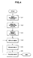
- step S11 host computer 201 reads setting-item file 208 installed in host computer 201.
- step S12 the meaning of setting-item file 208 read in step S11 is analyzed.
- name 403, setting value 404, effective value 405 and setting command 406 for each setting item are extracted, and data structure 601 shown in FIG. 5 is formed.
- step S13 a setting menu peculiar to emulator C is constructed in setting program 205 based on the result of the analysis performed in step S12. That is, when setting-item file 208 is described in the data structure shown in FIG. 3, adjacent data structures 601 shown in FIG. 5 are connected by pointer 606, to form data of the list structure shown in FIG. 5.
- Name 602, setting value 603, effective value 604 and setting command 605 shown in FIG. 5 correspond to name 403, setting value 404, effective value 405 and setting command 406 shown in FIG. 3, respectively.
- step S14 where the menu constructed in setting program 205 in step S13 is displayed on the picture surface of host computer 201.
- the process then proceeds to step S15, where a data input from the user in response to the menu displayed on the picture surface of host computer 201 is awaited.
- step S16 where the value of the corresponding setting item is changed in accordance with the value input in step S15.
- the result is displayed on the picture surface of host computer 201, and setting of various kinds of printing conditions and the like for printer 202 is performed.
- the processing of steps S14 - S16 is repeatedly executed, and the processing is terminated when an end command has been input.
- Various kinds of setting items thus set in host computer 201 are transmitted to printer 202 via cable 209, and are stored in emulator-C setting-item area 210 of non-volatile RAM 203.
- emulator-C setting-item area 210 of non-volatile RAM 203.
- FIG. 6 is a diagram illustrating a menu display according to another embodiment of the present invention.
- reference numeral 701 represents the display picture surface of host computer 201.
- Reference numeral 702 represents an item for setting interface conditions for connecting host computer 201 to printer 202. Two set values, i.e., RS-232C and CENTRO, are present for this item.
- Reference numeral 703 represents a setting item, which is effective only when the interface specification is set to RS-232C, for setting the transfer speed (baud rate) of RS-232C.
- Reference numeral 704 represents a setting item, which is meaningful only when the interface specification is set to RS-232C, for setting whether x on/x off is to be used when performing communication based on RS-232C.
- Reference numeral 705 represents a setting item, which is meaningful only when the interface specification is set to RS-232C, for setting whether ext/ack is to be used when performing communication based on RS-232C. As described above, the setting items 703 - 705 are effective only when the interface specification is set to RS-232C.
- Reference numeral 706 represents a setting item, which is meaningful only when the interface specification is set to CENTRO, for setting the data transfer speed when performing communication between host computer 201 and printer 202 with the specification conforming to CENTRO.
- setting item (C-speed) 706 is displayed with gray characters so as to notify the user that the item cannot be set, and the portion represented by reference numeral 707 is displayed with clear black characters so as to notify the user that the corresponding items can be set.
- the setting items baud rate 703, x on/x off 704, and etx/ack 705 are displayed with gray characters to notify the user that these items cannot be set.
- the setting item C-speed 706 is displayed with black characters.
- FIG. 8 is a cross-sectional view illustrating the internal structure of a laser-beam printer (LBP) 100 to which the present invention can be applied.
- LBP 100 is configured so that character patterns, form data and the like can be registered from a data source (a host computer or the like, not shown).
- main body 100 of the LBP inputs and stores character information (character codes), form information, macro commands and the like supplied from the host computer or the like connected to the LBP, forms character patterns, form patterns and the like in accordance with the above-described information, and forms an image on recording paper, serving as a recording medium.
- Operation panel 300 includes various kinds of switches, an LED (light-emitting diode) display unit and the like for various kinds of operations.
- Printer control unit 101 controls the entire main body 100 of the LBP, and analyzes character information and the like supplied from the host computer.
- Printer control unit 100 mainly converts character information into a video signal representing the corresponding character patterns, and outputs the video signal to laser driver 102.
- Laser driver 102 is a circuit for driving semiconductor laser 103, and switches on and off semiconductor laser 103 in accordance with the input video signal.
- Laser light 104 is deflected in a direction perpendicular to the plane of FIG. 8 by rotating polygonal mirror 105 to scan the surface of electrostatic drum 106.
- an electrostatic image of character patterns is formed on electrostatic drum 106.
- the latent image is developed by developing unit 107 provided around the circumference of electrostatic drum 106, and the developed image is transferred onto recording paper.
- the recording paper comprises cut sheets, which are accommodated in a sheet cassette mounted in main body 100 of the LBP. Each sheet of the recording paper is fed into the apparatus by sheet-feeding roller 109 and conveying rollers 111, and is supplied to electrostatic drum 106.
- the apparatus is not limited to the laser-beam printer, but an ink-jet printer (to be described below) or the like may also be used.
- FIG. 9 is a schematic diagram illustrating an ink-jet recording apparatus (IJRA) to which the present invention can be applied.
- carriage HC which engages helical groove 5004 of lead screw 5005 rotating via driving-force transmission gears 5001 and 5009 in accordance with the forward or reverse rotation of driving motor 5013 includes a pin (not shown), and is reciprocated in the directions of arrows a and b.
- Ink-jet cartridge IJC is mounted on carriage HC.
- Sheet-pressing plate 5002 presses the sheet of recording paper against platen 5000 along the moving direction of carriage HC.
- Photocoupler components 5007 and 5008 serve as home-position detection means for confirming the presence of lever 5006 of carriage HC in the region of these components, and performing, for example, switching of the direction of rotation of motor 5013.
- Member 5016 supports cap member 5022 which caps the front surface of the recording head.
- Reference numeral 5015 represents suction means for sucking the inside of the cap, which performs a suction recovery operation of the recording head via opening 5023 of the cap.
- Reference numeral 5017 represents a cleaning blade.
- Reference numeral 5019 represents a member for making cleaning blade 5017 movable back and forth, which is supported by supporting plate 5018 of the main body of the apparatus.
- the shape of cleaning blade 5017 is not limited to the illustrated shape, but any well-known cleaning blade may, of course, be used.
- Reference numeral 5021 represents a lever for starting suction for a suction recovery operation, which moves in accordance with the movement of cam 5020, which engages carriage HC.
- the driving force of driving motor 5013 is transmitted by known transmission means, such as a clutch or the like, to move lever 5021.
- the apparatus is configured so that each of the above-described capping, cleaning and suction recovery operations is performed at the corresponding position by the function of lead screw 5005 when carriage HC reaches the region of the home-position side. These operations can be performed provided that a desired operation is performed with an appropriate timing.
- FIG. 10 illustrating a control circuit
- interface 1700 for inputting recording signals
- MPU microprocessing unit
- program ROM 1702 for storing control programs executed by MPU 1701
- dynamic RAM 1703 for storing various kinds of data (the above-described recording signals, recording data to be supplied to the head, and the like).
- Gate array 1704 controls the supply of recording data to recording head 1708, and also controls data transfer between interface 1700, MPU 1701 and RAM 1703.
- Carrier motor 1710 carries recording head 1708, and conveyance motor 1709 conveys recording paper.
- Head driver 1705 drives the head.
- Motor drivers 1706 and 1707 drive conveyance motor 1709 and carrier motor 1710, respectively.
- the recording signal when a recording signal has entered interface 1700, the recording signal is converted into recording data for printing by gate array 1704 and MPU 1701. While motor drivers 1706 and 1707 drive the corresponding motors, recording head 1708 is driven in accordance with the recording data transmitted to head driver 1705, whereby printing is performed.
- the components of the present invention can be incorporated in the above-described configuration of control of the ink-jet printer. Accordingly, it is apparent that the present invention can be applied not only to the laser-beam printer, but also to the above-described ink-jet printer or the like.
- the present invention may be applied to a system comprising a plurality of apparatuses, or to an apparatus comprising a single unit.
- the present invention may, of course, be applied to a case in which the invention is achieved by supplying a system or an apparatus with programs for executing the invention.
- a single setting program can deal with addition of setting items peculiar to a newly purchased emulator or the like.
- various kinds of setting items can be set or changed in accordance with a function which has been newly added at the side of a printer.
Landscapes
- Engineering & Computer Science (AREA)
- Theoretical Computer Science (AREA)
- Human Computer Interaction (AREA)
- Physics & Mathematics (AREA)
- General Engineering & Computer Science (AREA)
- General Physics & Mathematics (AREA)
- Accessory Devices And Overall Control Thereof (AREA)
- Record Information Processing For Printing (AREA)
- Digital Computer Display Output (AREA)
- Feedback Control In General (AREA)
- Testing Electric Properties And Detecting Electric Faults (AREA)
- Tests Of Electronic Circuits (AREA)
Applications Claiming Priority (3)
| Application Number | Priority Date | Filing Date | Title |
|---|---|---|---|
| JP29847192A JP2859499B2 (ja) | 1992-11-09 | 1992-11-09 | 印刷システム及び前記システムにおける項目設定方法 |
| JP298471/92 | 1992-11-09 | ||
| JP29847192 | 1992-11-09 |
Publications (2)
| Publication Number | Publication Date |
|---|---|
| EP0597612A1 true EP0597612A1 (de) | 1994-05-18 |
| EP0597612B1 EP0597612B1 (de) | 2000-02-23 |
Family
ID=17860136
Family Applications (1)
| Application Number | Title | Priority Date | Filing Date |
|---|---|---|---|
| EP93308680A Expired - Lifetime EP0597612B1 (de) | 1992-11-09 | 1993-10-29 | Ausgabesteuerverfahren und -gerät |
Country Status (5)
| Country | Link |
|---|---|
| US (1) | US5751922A (de) |
| EP (1) | EP0597612B1 (de) |
| JP (1) | JP2859499B2 (de) |
| DE (1) | DE69327893T2 (de) |
| ES (1) | ES2141752T3 (de) |
Families Citing this family (12)
| Publication number | Priority date | Publication date | Assignee | Title |
|---|---|---|---|---|
| US6327051B1 (en) | 1995-12-22 | 2001-12-04 | Canon Kabushiki Kaisha | Printing control apparatus and method |
| JP2874639B2 (ja) * | 1996-04-05 | 1999-03-24 | 日本電気株式会社 | プリンタシステム |
| JPH1153277A (ja) | 1997-06-02 | 1999-02-26 | Fuji Xerox Co Ltd | 情報処理装置 |
| US20040205544A1 (en) * | 2002-01-03 | 2004-10-14 | International Business Machines Corporation | Inline error highlighting |
| US7143359B2 (en) * | 2002-01-03 | 2006-11-28 | International Business Machines Corporation | Emulating advanced graphical user interface elements in a hypermedia content browser |
| US7216303B2 (en) | 2002-01-03 | 2007-05-08 | International Business Machines Corporation | Menu emulation for content browser clients |
| US20040008360A1 (en) * | 2002-07-11 | 2004-01-15 | Corlene Ankrum | Setting device parameters to values associated with selected device-performable task |
| JP3783665B2 (ja) | 2002-08-05 | 2006-06-07 | ブラザー工業株式会社 | 画像形成装置及びネットワークシステム |
| KR100464092B1 (ko) * | 2002-12-13 | 2005-01-03 | 삼성전자주식회사 | 메뉴 편집 기능을 갖는 프린터 및 그의 메뉴 편집방법 |
| US7747967B2 (en) * | 2004-10-21 | 2010-06-29 | Kyocera Mita Corporation | Differential tree and dialog device settings menu |
| US7778495B2 (en) | 2004-11-05 | 2010-08-17 | Brother Kogyo Kabushiki Kaisha | System and device for image processing |
| KR102039553B1 (ko) * | 2012-08-31 | 2019-11-01 | 삼성전자 주식회사 | 사용자 디바이스에서 입력 문자를 이용한 지능형 서비스 제공 방법 및 장치 |
Citations (2)
| Publication number | Priority date | Publication date | Assignee | Title |
|---|---|---|---|---|
| EP0192021A2 (de) * | 1985-02-21 | 1986-08-27 | International Business Machines Corporation | Eingangs-Ausgangskonfigurationsänderung durch Verwender |
| EP0250777A2 (de) * | 1986-06-13 | 1988-01-07 | International Business Machines Corporation | Verfahren und Vorrichtungen zum Steuern von Druckern |
Family Cites Families (12)
| Publication number | Priority date | Publication date | Assignee | Title |
|---|---|---|---|---|
| JPH0786829B2 (ja) * | 1987-07-31 | 1995-09-20 | 株式会社東芝 | 電子機器装置 |
| US5276795A (en) * | 1989-03-15 | 1994-01-04 | Sun Microsystems, Inc. | Method and apparatus for selecting and executing defaults in a window based display system |
| CA1326563C (en) * | 1989-03-15 | 1994-01-25 | Anthony Hoeber | Method and apparatus for selecting and executing defaults in a window based display system |
| US5075874A (en) * | 1989-04-10 | 1991-12-24 | Eastman Kodak Company | Communications interface for computer output printer |
| US5050098A (en) * | 1989-08-25 | 1991-09-17 | Lexmark International, Inc. | Printer initialization system |
| US5307464A (en) * | 1989-12-07 | 1994-04-26 | Hitachi, Ltd. | Microprocessor and method for setting up its peripheral functions |
| US5268993A (en) * | 1990-06-04 | 1993-12-07 | Minolta Camera Kabushiki Kaisha | Printer |
| US5617518A (en) * | 1990-11-13 | 1997-04-01 | Hitachi, Ltd. | Output control method and system of servers |
| DE69233395T2 (de) * | 1991-03-12 | 2005-07-21 | Canon K.K. | Verfahren und Anordnung zur Datenausgabe |
| US5568594A (en) * | 1991-04-08 | 1996-10-22 | Kabushiki Kaisha Toshiba | Image forming apparatus with improved ability to emulate other image forming apparatuses |
| US5638497A (en) * | 1992-12-18 | 1997-06-10 | Dataproducts Corporation | Virtual printer |
| EP0674787B1 (de) * | 1992-12-18 | 2001-03-07 | Hitachi Koki Imaging Solutions, Inc. | Virtueller drucker |
-
1992
- 1992-11-09 JP JP29847192A patent/JP2859499B2/ja not_active Expired - Lifetime
-
1993
- 1993-10-29 EP EP93308680A patent/EP0597612B1/de not_active Expired - Lifetime
- 1993-10-29 DE DE69327893T patent/DE69327893T2/de not_active Expired - Lifetime
- 1993-10-29 ES ES93308680T patent/ES2141752T3/es not_active Expired - Lifetime
-
1996
- 1996-10-21 US US08/734,310 patent/US5751922A/en not_active Expired - Lifetime
Patent Citations (2)
| Publication number | Priority date | Publication date | Assignee | Title |
|---|---|---|---|---|
| EP0192021A2 (de) * | 1985-02-21 | 1986-08-27 | International Business Machines Corporation | Eingangs-Ausgangskonfigurationsänderung durch Verwender |
| EP0250777A2 (de) * | 1986-06-13 | 1988-01-07 | International Business Machines Corporation | Verfahren und Vorrichtungen zum Steuern von Druckern |
Non-Patent Citations (1)
| Title |
|---|
| "PARAMETER-SPECIFIC EXERCISING OF HARDWARE DEVICES", IBM TECHNICAL DISCLOSURE BULLETIN., vol. 33, no. 8, January 1991 (1991-01-01), NEW YORK US, pages 61 - 64 * |
Also Published As
| Publication number | Publication date |
|---|---|
| US5751922A (en) | 1998-05-12 |
| ES2141752T3 (es) | 2000-04-01 |
| DE69327893D1 (de) | 2000-03-30 |
| JPH06149490A (ja) | 1994-05-27 |
| JP2859499B2 (ja) | 1999-02-17 |
| DE69327893T2 (de) | 2000-08-17 |
| EP0597612B1 (de) | 2000-02-23 |
Similar Documents
| Publication | Publication Date | Title |
|---|---|---|
| EP0597612B1 (de) | Ausgabesteuerverfahren und -gerät | |
| EP0862109B1 (de) | Verfahren und Vorrichtung zur Informationsausgabe | |
| EP0577013B1 (de) | Gerät und Ausgabesteuerungsverfahren | |
| US6567183B1 (en) | Output apparatus and output method | |
| US5899614A (en) | Output method and apparatus | |
| EP0534723B1 (de) | Druckvorrichtung und Verfahren zum Speichern von verschiedenen Druckparameterdaten | |
| KR0155082B1 (ko) | 프린터 드라이버의 데이타 변환방법 | |
| US6397265B1 (en) | Print control apparatus for communicating with a selected external apparatus to control a printer | |
| JP3658025B2 (ja) | 電子機器及び該機器を有するデータ処理システム及び前記機器におけるデータ処理方法 | |
| EP0634731B1 (de) | Ausgabevorrichtung und -verfahren unter Verwendung mehrerer Datenverarbeitungseinrichtungen | |
| US5684930A (en) | Output apparatus and method with font control in plural output modes | |
| JP2871981B2 (ja) | 印刷装置及びその制御方法 | |
| JP3210118B2 (ja) | 印刷制御装置及び印刷制御方法 | |
| JPH06242895A (ja) | 印刷装置及び方法 | |
| JPH0675673A (ja) | インターフェース装置及び該装置を備える印刷装置 | |
| JPH08108600A (ja) | 情報処理装置,周辺装置並びに情報処理装置と周辺装置とを有する情報処理システムおよび情報処理システムの資源情報提示方法 | |
| JPH08267828A (ja) | 印刷装置 | |
| JPH0772991A (ja) | 印刷装置 | |
| JPH0691989A (ja) | 印刷装置及び方法 | |
| JPH06187105A (ja) | データ通信方法及び印刷装置 | |
| JPH0934659A (ja) | プリンタシステム | |
| JPH07125326A (ja) | 印刷装置および印刷制御方法 | |
| KR19980057504A (ko) | 페이지 프린터에서 비규격용지 인쇄방법 | |
| JPH09188017A (ja) | 印刷装置 | |
| JPH064241A (ja) | 印刷方法及び装置 |
Legal Events
| Date | Code | Title | Description |
|---|---|---|---|
| PUAI | Public reference made under article 153(3) epc to a published international application that has entered the european phase |
Free format text: ORIGINAL CODE: 0009012 |
|
| AK | Designated contracting states |
Kind code of ref document: A1 Designated state(s): DE ES FR GB IT |
|
| 17P | Request for examination filed |
Effective date: 19940930 |
|
| 17Q | First examination report despatched |
Effective date: 19961111 |
|
| GRAG | Despatch of communication of intention to grant |
Free format text: ORIGINAL CODE: EPIDOS AGRA |
|
| GRAG | Despatch of communication of intention to grant |
Free format text: ORIGINAL CODE: EPIDOS AGRA |
|
| GRAG | Despatch of communication of intention to grant |
Free format text: ORIGINAL CODE: EPIDOS AGRA |
|
| GRAH | Despatch of communication of intention to grant a patent |
Free format text: ORIGINAL CODE: EPIDOS IGRA |
|
| GRAH | Despatch of communication of intention to grant a patent |
Free format text: ORIGINAL CODE: EPIDOS IGRA |
|
| GRAA | (expected) grant |
Free format text: ORIGINAL CODE: 0009210 |
|
| AK | Designated contracting states |
Kind code of ref document: B1 Designated state(s): DE ES FR GB IT |
|
| REF | Corresponds to: |
Ref document number: 69327893 Country of ref document: DE Date of ref document: 20000330 |
|
| ET | Fr: translation filed | ||
| REG | Reference to a national code |
Ref country code: ES Ref legal event code: FG2A Ref document number: 2141752 Country of ref document: ES Kind code of ref document: T3 |
|
| ITF | It: translation for a ep patent filed | ||
| PLBE | No opposition filed within time limit |
Free format text: ORIGINAL CODE: 0009261 |
|
| 26N | No opposition filed | ||
| REG | Reference to a national code |
Ref country code: GB Ref legal event code: IF02 |
|
| PGFP | Annual fee paid to national office [announced via postgrant information from national office to epo] |
Ref country code: DE Payment date: 20101031 Year of fee payment: 18 |
|
| PGFP | Annual fee paid to national office [announced via postgrant information from national office to epo] |
Ref country code: IT Payment date: 20101014 Year of fee payment: 18 Ref country code: GB Payment date: 20101019 Year of fee payment: 18 |
|
| PGFP | Annual fee paid to national office [announced via postgrant information from national office to epo] |
Ref country code: FR Payment date: 20111109 Year of fee payment: 19 Ref country code: ES Payment date: 20111013 Year of fee payment: 19 |
|
| GBPC | Gb: european patent ceased through non-payment of renewal fee |
Effective date: 20121029 |
|
| REG | Reference to a national code |
Ref country code: FR Ref legal event code: ST Effective date: 20130628 |
|
| PG25 | Lapsed in a contracting state [announced via postgrant information from national office to epo] |
Ref country code: DE Free format text: LAPSE BECAUSE OF NON-PAYMENT OF DUE FEES Effective date: 20130501 Ref country code: GB Free format text: LAPSE BECAUSE OF NON-PAYMENT OF DUE FEES Effective date: 20121029 |
|
| REG | Reference to a national code |
Ref country code: DE Ref legal event code: R119 Ref document number: 69327893 Country of ref document: DE Effective date: 20130501 |
|
| PG25 | Lapsed in a contracting state [announced via postgrant information from national office to epo] |
Ref country code: IT Free format text: LAPSE BECAUSE OF NON-PAYMENT OF DUE FEES Effective date: 20121029 Ref country code: FR Free format text: LAPSE BECAUSE OF NON-PAYMENT OF DUE FEES Effective date: 20121031 |
|
| REG | Reference to a national code |
Ref country code: ES Ref legal event code: FD2A Effective date: 20140115 |
|
| PG25 | Lapsed in a contracting state [announced via postgrant information from national office to epo] |
Ref country code: ES Free format text: LAPSE BECAUSE OF NON-PAYMENT OF DUE FEES Effective date: 20121030 |