EP0597773A1 - Récipient métallique à double parois évacuée et son procédé de fabrication - Google Patents
Récipient métallique à double parois évacuée et son procédé de fabrication Download PDFInfo
- Publication number
- EP0597773A1 EP0597773A1 EP93402745A EP93402745A EP0597773A1 EP 0597773 A1 EP0597773 A1 EP 0597773A1 EP 93402745 A EP93402745 A EP 93402745A EP 93402745 A EP93402745 A EP 93402745A EP 0597773 A1 EP0597773 A1 EP 0597773A1
- Authority
- EP
- European Patent Office
- Prior art keywords
- vessel
- double
- sealing
- vacuum
- walled
- Prior art date
- Legal status (The legal status is an assumption and is not a legal conclusion. Google has not performed a legal analysis and makes no representation as to the accuracy of the status listed.)
- Granted
Links
Images


Classifications
-
- A—HUMAN NECESSITIES
- A47—FURNITURE; DOMESTIC ARTICLES OR APPLIANCES; COFFEE MILLS; SPICE MILLS; SUCTION CLEANERS IN GENERAL
- A47J—KITCHEN EQUIPMENT; COFFEE MILLS; SPICE MILLS; APPARATUS FOR MAKING BEVERAGES
- A47J41/00—Thermally-insulated vessels, e.g. flasks, jugs, jars
- A47J41/02—Vacuum-jacket vessels, e.g. vacuum bottles
- A47J41/022—Constructional details of the elements forming vacuum space
- A47J41/028—Constructional details of the elements forming vacuum space made of metal
-
- A—HUMAN NECESSITIES
- A47—FURNITURE; DOMESTIC ARTICLES OR APPLIANCES; COFFEE MILLS; SPICE MILLS; SUCTION CLEANERS IN GENERAL
- A47J—KITCHEN EQUIPMENT; COFFEE MILLS; SPICE MILLS; APPARATUS FOR MAKING BEVERAGES
- A47J41/00—Thermally-insulated vessels, e.g. flasks, jugs, jars
- A47J41/02—Vacuum-jacket vessels, e.g. vacuum bottles
-
- B—PERFORMING OPERATIONS; TRANSPORTING
- B23—MACHINE TOOLS; METAL-WORKING NOT OTHERWISE PROVIDED FOR
- B23K—SOLDERING OR UNSOLDERING; WELDING; CLADDING OR PLATING BY SOLDERING OR WELDING; CUTTING BY APPLYING HEAT LOCALLY, e.g. FLAME CUTTING; WORKING BY LASER BEAM
- B23K1/00—Soldering, e.g. brazing, or unsoldering
- B23K1/0008—Soldering, e.g. brazing, or unsoldering specially adapted for particular articles or work
- B23K1/001—Sealing small holes in metal containers, e.g. tins
-
- B—PERFORMING OPERATIONS; TRANSPORTING
- B23—MACHINE TOOLS; METAL-WORKING NOT OTHERWISE PROVIDED FOR
- B23K—SOLDERING OR UNSOLDERING; WELDING; CLADDING OR PLATING BY SOLDERING OR WELDING; CUTTING BY APPLYING HEAT LOCALLY, e.g. FLAME CUTTING; WORKING BY LASER BEAM
- B23K1/00—Soldering, e.g. brazing, or unsoldering
- B23K1/008—Soldering within a furnace
-
- F—MECHANICAL ENGINEERING; LIGHTING; HEATING; WEAPONS; BLASTING
- F17—STORING OR DISTRIBUTING GASES OR LIQUIDS
- F17C—VESSELS FOR CONTAINING OR STORING COMPRESSED, LIQUEFIED OR SOLIDIFIED GASES; FIXED-CAPACITY GAS-HOLDERS; FILLING VESSELS WITH, OR DISCHARGING FROM VESSELS, COMPRESSED, LIQUEFIED, OR SOLIDIFIED GASES
- F17C3/00—Vessels not under pressure
- F17C3/02—Vessels not under pressure with provision for thermal insulation
- F17C3/08—Vessels not under pressure with provision for thermal insulation by vacuum spaces, e.g. Dewar flask
-
- B—PERFORMING OPERATIONS; TRANSPORTING
- B23—MACHINE TOOLS; METAL-WORKING NOT OTHERWISE PROVIDED FOR
- B23K—SOLDERING OR UNSOLDERING; WELDING; CLADDING OR PLATING BY SOLDERING OR WELDING; CUTTING BY APPLYING HEAT LOCALLY, e.g. FLAME CUTTING; WORKING BY LASER BEAM
- B23K2101/00—Articles made by soldering, welding or cutting
- B23K2101/04—Tubular or hollow articles
- B23K2101/12—Vessels
-
- F—MECHANICAL ENGINEERING; LIGHTING; HEATING; WEAPONS; BLASTING
- F17—STORING OR DISTRIBUTING GASES OR LIQUIDS
- F17C—VESSELS FOR CONTAINING OR STORING COMPRESSED, LIQUEFIED OR SOLIDIFIED GASES; FIXED-CAPACITY GAS-HOLDERS; FILLING VESSELS WITH, OR DISCHARGING FROM VESSELS, COMPRESSED, LIQUEFIED, OR SOLIDIFIED GASES
- F17C2201/00—Vessel construction, in particular geometry, arrangement or size
- F17C2201/01—Shape
- F17C2201/0104—Shape cylindrical
- F17C2201/0109—Shape cylindrical with exteriorly curved end-piece
-
- F—MECHANICAL ENGINEERING; LIGHTING; HEATING; WEAPONS; BLASTING
- F17—STORING OR DISTRIBUTING GASES OR LIQUIDS
- F17C—VESSELS FOR CONTAINING OR STORING COMPRESSED, LIQUEFIED OR SOLIDIFIED GASES; FIXED-CAPACITY GAS-HOLDERS; FILLING VESSELS WITH, OR DISCHARGING FROM VESSELS, COMPRESSED, LIQUEFIED, OR SOLIDIFIED GASES
- F17C2201/00—Vessel construction, in particular geometry, arrangement or size
- F17C2201/01—Shape
- F17C2201/0104—Shape cylindrical
- F17C2201/0119—Shape cylindrical with flat end-piece
-
- F—MECHANICAL ENGINEERING; LIGHTING; HEATING; WEAPONS; BLASTING
- F17—STORING OR DISTRIBUTING GASES OR LIQUIDS
- F17C—VESSELS FOR CONTAINING OR STORING COMPRESSED, LIQUEFIED OR SOLIDIFIED GASES; FIXED-CAPACITY GAS-HOLDERS; FILLING VESSELS WITH, OR DISCHARGING FROM VESSELS, COMPRESSED, LIQUEFIED, OR SOLIDIFIED GASES
- F17C2201/00—Vessel construction, in particular geometry, arrangement or size
- F17C2201/05—Size
- F17C2201/058—Size portable (<30 l)
-
- F—MECHANICAL ENGINEERING; LIGHTING; HEATING; WEAPONS; BLASTING
- F17—STORING OR DISTRIBUTING GASES OR LIQUIDS
- F17C—VESSELS FOR CONTAINING OR STORING COMPRESSED, LIQUEFIED OR SOLIDIFIED GASES; FIXED-CAPACITY GAS-HOLDERS; FILLING VESSELS WITH, OR DISCHARGING FROM VESSELS, COMPRESSED, LIQUEFIED, OR SOLIDIFIED GASES
- F17C2203/00—Vessel construction, in particular walls or details thereof
- F17C2203/03—Thermal insulations
- F17C2203/0391—Thermal insulations by vacuum
-
- F—MECHANICAL ENGINEERING; LIGHTING; HEATING; WEAPONS; BLASTING
- F17—STORING OR DISTRIBUTING GASES OR LIQUIDS
- F17C—VESSELS FOR CONTAINING OR STORING COMPRESSED, LIQUEFIED OR SOLIDIFIED GASES; FIXED-CAPACITY GAS-HOLDERS; FILLING VESSELS WITH, OR DISCHARGING FROM VESSELS, COMPRESSED, LIQUEFIED, OR SOLIDIFIED GASES
- F17C2203/00—Vessel construction, in particular walls or details thereof
- F17C2203/06—Materials for walls or layers thereof; Properties or structures of walls or their materials
- F17C2203/0602—Wall structures; Special features thereof
- F17C2203/0612—Wall structures
- F17C2203/0626—Multiple walls
- F17C2203/0629—Two walls
-
- F—MECHANICAL ENGINEERING; LIGHTING; HEATING; WEAPONS; BLASTING
- F17—STORING OR DISTRIBUTING GASES OR LIQUIDS
- F17C—VESSELS FOR CONTAINING OR STORING COMPRESSED, LIQUEFIED OR SOLIDIFIED GASES; FIXED-CAPACITY GAS-HOLDERS; FILLING VESSELS WITH, OR DISCHARGING FROM VESSELS, COMPRESSED, LIQUEFIED, OR SOLIDIFIED GASES
- F17C2203/00—Vessel construction, in particular walls or details thereof
- F17C2203/06—Materials for walls or layers thereof; Properties or structures of walls or their materials
- F17C2203/0634—Materials for walls or layers thereof
- F17C2203/0636—Metals
- F17C2203/0639—Steels
- F17C2203/0643—Stainless steels
-
- F—MECHANICAL ENGINEERING; LIGHTING; HEATING; WEAPONS; BLASTING
- F17—STORING OR DISTRIBUTING GASES OR LIQUIDS
- F17C—VESSELS FOR CONTAINING OR STORING COMPRESSED, LIQUEFIED OR SOLIDIFIED GASES; FIXED-CAPACITY GAS-HOLDERS; FILLING VESSELS WITH, OR DISCHARGING FROM VESSELS, COMPRESSED, LIQUEFIED, OR SOLIDIFIED GASES
- F17C2209/00—Vessel construction, in particular methods of manufacturing
- F17C2209/21—Shaping processes
- F17C2209/2109—Moulding
-
- F—MECHANICAL ENGINEERING; LIGHTING; HEATING; WEAPONS; BLASTING
- F17—STORING OR DISTRIBUTING GASES OR LIQUIDS
- F17C—VESSELS FOR CONTAINING OR STORING COMPRESSED, LIQUEFIED OR SOLIDIFIED GASES; FIXED-CAPACITY GAS-HOLDERS; FILLING VESSELS WITH, OR DISCHARGING FROM VESSELS, COMPRESSED, LIQUEFIED, OR SOLIDIFIED GASES
- F17C2270/00—Applications
- F17C2270/05—Applications for industrial use
- F17C2270/0509—"Dewar" vessels
Definitions
- the present invention relates to a metallic double-walled vessel such as a portable thermos, pot, jar or the like.
- a method for producing a metallic evacuated double-walled vessel there are available such conventional methods as, for example, a method wherein the evacuation of the space between an inner and an outer vessel is carried out by means of a chip tube attached to the outer vessel, and the chip tube is then pressure welded and sealed (Japanese Patent Application, laid open number Sho 59-37914, Japanese Patent Application laid open number Sho 59-103633); a method wherein an evacuation opening is provided to the outer vessel, a brazing metal material is piled around the periphery of the evacuation hole, a sealing member is placed on top of this with an interval of space being maintained between the sealing member and the evacuation hole, heat evacuation is carried out in a vacuum heating furnace, after which, the temperature is raised to the melting temperature of the brazing metal material, the sealing member is brazed, and the vessel is thus vacuum sealed (Japanese Patent Application laid open number Sho 58-192516); and a method wherein a small hole or cut-out is punched in the outer vessel, a brazing metal material is
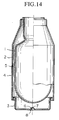
- FIG 14 is provided in order to explain an example of the production method of a conventional metallic evacuated double-walled vessel.
- This figure shows the state of a metallic evacuated double-walled vessel prior to vacuum sealing.
- This prior to vacuum sealing vessel consists of an inner casing 1 which is cylindrical in shape and has a bottom, and an outer casing 4 which consists of a cylindrical outer casing body portion 2 and an outer casing bottom portion 3.
- the mouth portion of outer casing body portion 2 is air tightly joined to the mouth portion of inner casing 1.
- outer casing bottom portion 3 is air tightly joined to the opening at one end of the vessel which is opposite the mouth portion of the outer casing body portion 2.
- a concavity 6 which is indented inward toward inner casing 1 is formed.
- a small hole 7 evacuation hole or slit for evacuation is formed passing through a cavity 5 between the inner casing 1 and the outer casing 4.
- a sealing hot charge 8 such as metallic brazing material, in a paste form is disposed in concavity 6, and the prior-to-sealing vessel is placed in a vacuum heating furnace. Melting and heating of the sealing hot charge 8 is carried out as the inside of the vacuum heating furnace is evacuate to a fixed degree of vacuum. The melted sealing hot charge 8 flows from the periphery therearound into the evacuation hole 7, plugging evacuation hole 7. Following this, sealing hot charge 8 is cooled and hardens, vacuum sealing evacuation hole 7. In this manner, a metallic evacuated double-walled vessel having an evacuated thermal insulating layer between the inner casing 1 and the outer casing 4 is produced (Utility Model Application Hei 2-26837).
- a sealing hot charge 8 in a paste form is disposed about the periphery of concavity 6, the sealing hot charge 8 is melted during vacuum sealing, and flows along the incline of concavity 6 provided to evacuation hole 7, sealing evacuation hole 7. Accordingly, the manner of flow of the melted sealing hot charge 8 changes due to the quantity used, or as a result of the inclination or surface features of the outer casing bottom portion 3 and the concavity 6, the flow of hot charge 8 into evacuation hole 7 becomes unstable, resulting in insufficient sealing. In order to prevent such inconveniences, more sealing hot charge 8 than actually necessary must be used, causing production costs for the vessel to increase.
- Figure 1 is a front cross sectional view of a double-walled vessel prior to sealing, showing a first embodiment of the present invention.
- Figure 2 is a view of the bottom surface of the same prior-to-sealing vessel.
- Figure 3 is a cross sectional view of an essential component of the same prior-to-sealing vessel.
- Figure 4 is a cross sectional view of an essential component showing the state following vacuum sealing of the same vessel.
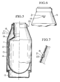
- Figure 5 is a front cross sectional view of a vessel prior to sealing, showing a second embodiment of the present invention.
- Figure 6 is a front view of an essential component of the same prior-to-sealing vessel.
- Figure 7 is a cross sectional view of an essential component of the same prior-to-sealing vessel.
- Figure 8 is a front cross sectional view of a double-walled vessel prior to sealing, showing a third embodiment of the present invention.
- Figure 9 is a view of the bottom surface of the same prior-to-sealing vessel.
- Figure 10 is an enlarged cross sectional view of an essential component of the evacuated double-walled vessel obtained by carrying out vacuum sealing to the same double-walled vessel.
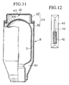
- Figure 11 is a front cross sectional view of a double-walled vessel prior to sealing, showing a fourth embodiment of the present invention.
- Figure 12 is a bottom view showing an enlargement of an essential component of the same double-walled vessel.
- Figure 13 is a front cross sectional view of the double-walled vessel prior to sealing showing a fifth embodiment of the present invention.
- Figure 14 is a front cross sectional view of a prior-to-sealing vessel which is provided to explain the conventional art related to the present invention.
- the present invention was conceived taking into consideration the aforementioned circumstances, and has as its objective the provision of a metallic evacuated double-walled vessel for which it is possible to carry out with surety the placement in an evacuation hole of a sealing hot charge for sealing the evacuation hole, and the sealing of the evacuation hole with the sealing hot charge, at a low cost, thus making possible a reduction in production costs.
- the first invention of the present invention is a production method for a metallic evacuated double-walled vessel characterized in that, in a method for making a metallic evacuated double-walled vessel wherein the vessel consists of a metallic inner and outer vessel and an evacuated thermal insulating layer is formed in the cavity between the inner vessel and the outer vessel, the method comprises the steps of: forming a prior-to-sealing double-walled vessel by joining the mouth portions of the metallic inner and outer vessels to each other in a unitary fashion, forming a concavity in one of either the inner vessel and the outer vessel, and punching an evacuation hole for vacuum evacuation in the concavity; disposing at the time of vacuum heating, a sealing hot charge in a solid form at a position vertically above the evacuation hole leaving a space therebetween; placing the prior-to-sealing vessel in a vacuum heating furnace, and performing vacuum evacuation of the cavity between the inner vessel and the out vessel via the evacuation hole until a fixed degree of vacuum is reached; vacuum sealing the vessel by heating and melting
- This first invention allows vacuum sealing to be carried out with greater surety than that provided by the conventional method wherein vacuum sealing is performed through the flowing of the melted sealing hot charge. Accordingly, by means of this first invention it is possible to lower the rate of defective vacuum sealings, and to improve yield.
- the second invention of the present invention is a production method for a metallic evacuated double-walled vessel characterized in that, in a method for making a metallic evacuated double-walled vessel wherein the vessel consists of a metallic inner and outer vessel and an evacuated thermal insulating layer is formed in the cavity between the inner vessel and the outer vessel, the method comprises the steps of: forming a double-walled vessel by joining together an inner vessel and an outer vessel, one of either the inner vessel and the outer vessel having an evacuation hole; disposing a sealing material consisting of low temperature melting glass, the softening temperature of which is from 200°C to 600°C, in the vicinity of the evacuation opening; placing the double-walled vessel inside a vacuum heating furnace, and vacuum evacuating the cavity between the inner and outer vessels at a temperature lower than the softening temperature of the sealing material; heating the double-walled vessel to a temperature higher than the softening temperature of the sealing material, and sealing the evacuation hole by the allowing the softened sealing material to flow into the evacuation hole.
- the evacuation hole punched in one of either of the inner vessel or the outer vessel of the metallic double-walled vessel is sealed using a sealing material which consists of low temperature melting glass which softens at a temperature of from 200°C to 600°C, it is possible to reduce the temperature for vacuum sealing as compared to the conventional brazing method. For this reason, the temperatures used in the vacuum heating furnace can be lowered, equipment costs are reduced, and the production costs for the article are lowered.
- the low temperature melting glass used in the present invention is advantageous in that, even if oxidants are present on the surface of the metallic double-walled vessel, wettability is not impaired, making it possible to carry out a preferable sealing. Accordingly, it is also possible to omit the process of removing oxidants are removed by heating the surface of the metallic double-walled vessel to a high temperature. Production costs for the evacuated double-walled vessel are thereby further reduced.
- all vacuum evacuation and sealing operations can be carried out at a comparatively low temperatures in the range of from 200°C to 600°C, and the hardness of metallic material such as stainless steel or the like which constructs the vessel can be increased by low temperature annealing.
- the vessel can be made thinner, and the overall weight of the evacuated double-walled vessel can be reduced.
- prior-to-sealing vessel 10 the vessel (hereinafter, referred to as prior-to-sealing vessel 10) shown in Figures 1 through 3 is first prepared.
- This prior-to-sealing vessel 10 consists of a metallic inner casing 11 which is cylindrical in shape and has a bottom, and a metallic outer casing 14 which similarly is cylindrical in shape and has a bottom, the inner casing 11 and outer casing 14 being joined at the mouth portions thereof.
- Outer casing 14 is formed from an outer casing body portion 12 which has a shoulder portion 19 the diameter of which as it approaches the mouth portion gradually reduces in the vicinity of the outer end portion of the mouth portion, and an outer casing bottom portion 13 which is air tightly joined to the opening of outer casing body portion 12 which is opposite the mouth portion thereof.
- Stainless steel is, in particular, preferably used as the metallic material which composes inner casing 11 and outer casing 14.
- a semi-spherical concavity 16 is indented inward toward inner casing 11 at the approximate center portion of outer casing bottom portion 13.
- the diameter Do of concavity 16 is preferably 3 to 15 mm.
- An evacuation hole 17 consisting of a small hole having a diameter A of 0.1 to 2 mm is formed in the approximate center of concavity 16.
- a cylindrical solid sealing hot charge 18 is disposed in concavity 16.
- the diameter d of this solid sealing hot charge 18 is preferably 0.3 to 3 mm, and the length L thereof is within the limits such that A ⁇ L ⁇ Do.
- this solid sealing hot charge 18 is attached in concavity 16 so as to be positioned vertically above evacuation hole 17, with an interval of spacing therebetween.
- the above described prior-to-sealing vessel 10 is contained within a vacuum heating furnace in a state such that the mouth portion is directed downward.
- the vacuum heating process is then carried out. Namely, following vacuum evacuation of cavity 15 to a fixed degree of vacuum via evacuation hole 17 at a temperature below the melting temperature of sealing hot charge 18, the temperature is raised above the melting temperature of sealing hot charge 18, melting sealing hot charge 18 and causing it to drop down onto evacuation hole 17 which is positioned vertically thereunder, and onto the vicinity thereabout.
- FIG. 4 shows the state where evacuation hole 17 has been sealed in this manner by sealing hot charge 18.
- hole diameter A of evacuation hole 17 is less than 0.1 mm, then it is possible that the evacuation of cavity 15 will not be sufficient. Likewise, if hole diameter A is larger than 2.0 mm, due to the surface tension of the melted sealing hot charge 18, it is possible that the hole will not be plugged sufficiently by sealing hot charge 18. Further, provided that sealing hot charge 18 is in a solid form, a metallic brazing material or a low temperature melting glass may also be utilized.
- a metallic evacuated double-walled vessel which consists of metallic inner casing 11 and an outer casing 14 and has an evacuated thermal insulating layer formed between inner casing 11 and outer casing 14, is produced.
- a cylindrical, solid sealing hot charge 18 is attached in concavity 16 so as to be positioned vertically above evacuation hole 17, and the prior-to-sealing vessel 10 is contained then within a vacuum heating furnace.
- cavity 15 is vacuum evacuated to a fixed degree of vacuum via evacuation hole 17 at a temperature below the melting temperature of sealing hot charge 18.
- the temperature is raised above the melting point of sealing hot charge 18, melting sealing hot charge 18 and causing it to drop down under its own weight onto evacuation hole 17 positioned vertically thereunder and onto the vicinity thereabout.
- the position for the provision of concavity 16 is not limited as aforementioned to the outer casing bottom portion 13, but may be provided to the inner casing 11 or to the shoulder portion 19 of outer casing body portion 12, as is the case in a later embodiment.
- the bottom portion of concavity 16 may also be level or inclined.
- the shape of evacuation hole 17 which is punched in concavity 16 may be a slit shaped long hole, or may comprise several small aligned holes. The position at which evacuation hole 17 is punched in concavity 16 is not limited to the approximate center of concavity 16, but may be elsewhere about the vicinity thereof.
- solid sealing hot charge 18 may be other than a cylindrical shape, provided that it is a solid material the length of which is longer than the diameter of evacuation hole 17, and that the shape of which has dimensions which do not interfere with vacuum evacuation when it sealing hot charge 18 disposed directly above evacuation hole 17.
- the cubic volume of sealing hot charge 18 is not limited to a cubic volume as calculated from the above described dimensions. Rather, provided that the cubic volume is with limits which proscribe a minimum value for the cubic volume for the sealing hot charge 18 such that the sealing hot charge 18 has at least a thickness of 0.1 mm and can cover twice the diameter of the minimum cubic volume of evacuation hole 17, and a maximum value for the cubic volume of sealing hot charge 18 such that it does not exceed the inner cubic volume of the concavity so that external impacts are not locally concentrated.
- the prior-to-sealing vessel 20 used in this embodiment differs from the prior-to-sealing vessel 10 used previous embodiment in that a pocket shaped concavity 21 is formed to shoulder portion 19 of the outer casing body portion 12, small evacuation hole 22 is punched in concavity 21, and a cylindrical sealing hot charge 18 is attached vertically above the evacuation hole 22.
- prior-to-sealing vessel 20 is placed upright, namely placed with the mouth portion of the vessel directed upward, and contained within a vacuum heating furnace. Vacuum heating is then carried out.
- cavity 15 is first vacuum evacuated to a fixed degree of vacuum via evacuation hole 22 at a temperature below the melting temperature of sealing hot charge 18. Then, the temperature is raised above the melting temperature of sealing hot charge 18, melting sealing hot charge 18 and causing it to drop down onto evacuation hole 22 which is positioned directly therebelow, and onto the vicinity around evacuation hole 22.
- Sealing hot charge 18 which has dropped down onto evacuation hole 22 and the vicinity therearound collects on evacuation hole 22 and enters into evacuation hole 22 as a result of capillary phenomenon. Following this, sealing hot charge 18 cools and hardens, sealing evacuation hole 22 with surety.
- prior-to-sealing vessel 20 is placed in a vacuum heating furnace with the mouth portion thereof directed upward during vacuum heating, a support device for supporting the prior-to-sealing vessel in the vacuum heating furnace is unnecessary. Thus, the operations of inserting and removing the vessel for vacuum heating are facilitated.
- FIGS 8 through 10 are provided to explain a third embodiment of the production method for a metallic evacuated double-walled vessel according to the present invention.
- the metallic evacuated double-walled vessel produced here is a portable thermos which consists of a stainless steel inner vessel 31 and a stainless steel outer vessel 34 which are joined together, with a cavity 35 between the inner vessel 31 and the outer vessel 34 forming an evacuated thermal insulating layer.
- outer vessel 34 In outer vessel 34, outer vessel bottom member 33 is joined air tightly to the bottom end of approximately cylindrical outer vessel body 32.
- Concavity 40 which is indented to form a semi-spherical shape is formed to the approximate center portion of outer vessel bottom member 33.
- a small evacuation hole 41 is punched in the center of concavity 40.
- the mouth diameter of evacuation hole 41 is preferably 0.1 to 2.0 mm.
- inner vessel 31 and outer vessel body 32 are air tightly joined at the mouth portions thereof, while at the same time, outer vessel bottom member 33 is air tightly joined to outer vessel body 32, forming prior-to-sealing double-walled vessel A (hereinafter, referred to as double-walled vessel).
- double-walled vessel prior-to-sealing double-walled vessel A
- the mouth portion of double-walled vessel A is directed downward, and a rod shaped sealing material 42 is attached inside concavity 40 of outer vessel bottom member 33 with a interval of space maintained between sealing material 42 and evacuation hole 41.
- a low temperature melting glass the softening point of which is from 200°C to 600°C is used in sealing material 42.
- Solder glass derived from B2O3-PbO, B2O3-ZnO, PbO-B2O3-ZnO-SiO2, PbO-B2O3-Al2O3-SiO2, PbO-B2O3-SiO2, or PbO-B2O3-BaO-SiO2 may be used as the low temperature melting glass.
- a material having a coefficient of thermal expansion similar to that of stainless steel which is the material of the double-walled vessel is preferable.
- sealing material 42 may be simply pushed into concavity 40.
- the shape of sealing material 42 is not limited to a rod shape, but may also be a solid shape.
- double-walled vessel A to which sealing material 42 is attached, is transferred to and disposed within a vacuum heating furnace in an inverted position.
- Vacuum heating is carried out by vacuum evacuating the inside of the furnace while heating is performed.
- the temperature for the vacuum heating is set so as to be within the range of 200°C to 600°C and such that sealing material 42 does not soften.
- the gas in the cavity between inner vessel 31 and outer vessel 34 is expelled through evacuation hole 41.
- the temperature inside the furnace is raised to a temperature which is in the range from 200°C to 600°C and which is a temperature above the softening point of sealing material 42.
- Sealing material 42 is softened and drops down under its own weight onto evacuation hole 41 and the vicinity thereabout, sealing evacuation hole 41. Following this vacuum sealing, the vessel is removed from the furnace. As a result, as shown in Figure 10, evacuation hole 41 is sealed with sealing material 42 which consists of low temperature melting glass, thus obtaining a stainless steel thermos (metallic evacuated double-walled vessel) having an evacuated thermal insulating layer 36 between inner vessel 31 and outer vessel 34.
- the double-walled vessel is heated at a temperature in the range of 200°C to 600°C, and the hardness of the stainless steel, which is the material of the double-walled vessel, is increased by low temperature annealing. Accordingly, the thickness of the stainless steel necessary to obtain the required shock and impact resistance is reduced. Thus, the vessel can be made thinner.
- the production method according to the present embodiment by sealing the evacuation hole of the metallic double-walled vessel by using a sealing material consisting of a low temperature melting glass which has a softening temperature in the range of 200° to 600°C, it is possible to reduce the temperature of vacuum sealing as compared to the convention brazing method. For this reason, the temperature utilized within the vacuum heating furnace can be lowered, equipment costs are reduced, and the production costs for the article can be lowered.
- This low temperature melting glass is advantageous in that wettability is not impaired even if oxidants are present on the surface of the double-walled vessel, making it possible to carry out a preferable sealing. Accordingly, it is possible to omit the process for removing oxidants by heating to a high temperature the surface of the double-walled vessel. Thus, the production costs for an evacuated double-walled vessel can be reduced.
- all vacuum evacuation and sealing operations can be carried out at comparatively low temperatures in the range of from 200°C to 600°C, and the hardness of the metallic material such as stainless steel or the like which composes the vessel can be increased by low temperature annealing.
- the vessel can be made thinner, and the overall weight of the evacuated double-walled vessel can be reduced.
- Figures 11 and 12 are provided to explain a fourth embodiment of the production method for a metallic evacuated double-walled vessel according to the present invention.
- the double-walled vessel B shown in these figures is equipped with almost entirely the same structural elements as those shown in Figures 8 and 9.
- Structural elements shown in Figures 11 and 12 which are identical to those in Figures 8 and 9 have been labeled with the same symbols.
- a long groove 43 is formed in the center portion of the bottom surface side of outer vessel bottom member 33, and a slit-shaped long hole 44 (evacuation hole) is formed in the bottom of long groove 43.
- a rod shaped sealing material 42 consisting of low temperature melting glass and having a length which is shorter than the length of the slit shaped long hole 44 is disposed inside long groove 43 of the double-walled vessel B.
- double-walled vessel B is placed inside a vacuum heating furnace, and vacuum heating is carried out while heating to a temperature which is within the range of 200°C to 600°C and is below the temperature at which sealing material 42 softens.
- the temperature inside the furnace is raised to a temperature which is in the range of from 200°C to 600°C and which is a temperature above the softening point of sealing material 42.
- Sealing material 42 is softened and flows onto slit shaped long hole 44, sealing it, and a stainless steel thermos (evacuated double-walled vessel) is thereby obtained.
- FIG. 13 is provided to explain a fifth embodiment of the production method for a metallic evacuated double-walled vessel according to the present invention.
- the double-walled vessel C shown in these figures is equipped with almost entirely the same structural elements as those shown in Figures 8 and 9. Structural elements shown in Figure 13 which are identical to those in Figures 8 and 9 have been labeled with the same symbols.
- a pocket shaped concavity 40 is provided to the shoulder portion of the outer vessel body 32, and a small evacuation hole 41 is formed inside concavity 40.
- Double-walled vessel C is then placed inside a vacuum heating furnace, and, as in the previous example, vacuum heating is carried out while heating to a temperature which is within the range of 200°C to 600°C and is below the temperature at which sealing material 42 softens. After evacuating to a pressure of 1 x 10 ⁇ 2 torr or less, the temperature inside the furnace is raised to a temperature which is in the range of from 200°C to 600°C and which is above the softening point of sealing material 42.
- Sealing material 42 is softened and drops down under its own weight directly onto evacuation hole 41 and the vicinity therearound, sealing evacuation hole 41. After vacuum sealing, the vessel is removed from the furnace, and a stainless steel thermos (evacuated double-walled vessel) is thereby obtained.
Landscapes
- Engineering & Computer Science (AREA)
- Physics & Mathematics (AREA)
- Thermal Sciences (AREA)
- Mechanical Engineering (AREA)
- Food Science & Technology (AREA)
- General Engineering & Computer Science (AREA)
- Thermally Insulated Containers For Foods (AREA)
Priority Applications (1)
| Application Number | Priority Date | Filing Date | Title |
|---|---|---|---|
| EP96202986A EP0755646B1 (fr) | 1992-11-12 | 1993-11-09 | Récipient métallique à double parois évacuée et son procédé de fabrication |
Applications Claiming Priority (4)
| Application Number | Priority Date | Filing Date | Title |
|---|---|---|---|
| JP302621/92 | 1992-11-12 | ||
| JP4302621A JP2774746B2 (ja) | 1992-11-12 | 1992-11-12 | 金属製真空二重容器の製造方法 |
| JP4327048A JP2774748B2 (ja) | 1992-12-07 | 1992-12-07 | 金属製真空二重容器及びその製造方法 |
| JP327048/92 | 1992-12-07 |
Related Child Applications (1)
| Application Number | Title | Priority Date | Filing Date |
|---|---|---|---|
| EP96202986A Division EP0755646B1 (fr) | 1992-11-12 | 1993-11-09 | Récipient métallique à double parois évacuée et son procédé de fabrication |
Publications (2)
| Publication Number | Publication Date |
|---|---|
| EP0597773A1 true EP0597773A1 (fr) | 1994-05-18 |
| EP0597773B1 EP0597773B1 (fr) | 1998-04-22 |
Family
ID=26563196
Family Applications (2)
| Application Number | Title | Priority Date | Filing Date |
|---|---|---|---|
| EP93402745A Expired - Lifetime EP0597773B1 (fr) | 1992-11-12 | 1993-11-09 | Procédé de fabrication d'un récipient métallique à double parois évacuée |
| EP96202986A Expired - Lifetime EP0755646B1 (fr) | 1992-11-12 | 1993-11-09 | Récipient métallique à double parois évacuée et son procédé de fabrication |
Family Applications After (1)
| Application Number | Title | Priority Date | Filing Date |
|---|---|---|---|
| EP96202986A Expired - Lifetime EP0755646B1 (fr) | 1992-11-12 | 1993-11-09 | Récipient métallique à double parois évacuée et son procédé de fabrication |
Country Status (6)
| Country | Link |
|---|---|
| EP (2) | EP0597773B1 (fr) |
| KR (1) | KR100250778B1 (fr) |
| CN (1) | CN1053804C (fr) |
| DE (2) | DE69318107T2 (fr) |
| MY (1) | MY109618A (fr) |
| SG (1) | SG47681A1 (fr) |
Cited By (5)
| Publication number | Priority date | Publication date | Assignee | Title |
|---|---|---|---|---|
| GB2404911A (en) * | 2003-08-15 | 2005-02-16 | Stephen Tew | Insulated containers |
| US7383964B2 (en) | 2003-08-13 | 2008-06-10 | Cool-System Bev. Gmbh | Container with at least one vacuum chamber with an access opening especially a beverage container, such as a beer barrel on the like |
| BE1023257B1 (nl) * | 2015-12-22 | 2017-01-12 | Allibert Hovac Nv | Glazen container voor een isolerende fles |
| CN107477352A (zh) * | 2017-09-13 | 2017-12-15 | 云南电网有限责任公司电力科学研究院 | 一种低漏热低温容器 |
| WO2019007099A1 (fr) * | 2017-07-01 | 2019-01-10 | 佛山市铠斯钛科技有限公司 | Nouveau procédé de fabrication d'un récipient d'isolation thermique sous vide, et récipient d'isolation thermique sous vide ainsi fabriqué |
Families Citing this family (10)
| Publication number | Priority date | Publication date | Assignee | Title |
|---|---|---|---|---|
| JP2000005083A (ja) * | 1998-04-23 | 2000-01-11 | Nippon Sanso Kk | 金属製真空二重壁容器とその製造方法 |
| KR20040011223A (ko) * | 2002-07-29 | 2004-02-05 | 원제돈 | 진공보온병과 이의 제조 방법 |
| DE102004010816B4 (de) * | 2003-08-13 | 2005-08-04 | Cool-System Bev. Gmbh | Behältnis mit wenigstens einer Vakuumkammer mit einer Zugangsöffnung, insbesondere Getränkebehältnis wie Bierfass oder dergleichen |
| RU2263455C1 (ru) * | 2004-06-07 | 2005-11-10 | Государственное образовательное учреждение высшего профессионального образования "Пермский государственный технический университет" | Способ изготовления термоса |
| KR101415603B1 (ko) * | 2013-01-16 | 2014-08-06 | 이영희 | 정수기용 온수통의 진공 실링방법 |
| US20190039810A1 (en) * | 2016-02-05 | 2019-02-07 | Yeti Coolers, Llc | Insulating container and method of forming such a container |
| CN107380740B (zh) * | 2017-07-01 | 2019-08-06 | 佛山市铠斯钛科技有限公司 | 一种高效的保温容器制造方法及其制造的保温容器 |
| CN107380741B (zh) * | 2017-07-01 | 2019-09-10 | 佛山市铠斯钛科技有限公司 | 一种气密性强保温容器的制造方法及其制造的保温容器 |
| CN111417330A (zh) * | 2017-07-07 | 2020-07-14 | 概念集团有限责任公司 | 用于真空绝热制品的接合构造 |
| CN109465601A (zh) * | 2018-11-13 | 2019-03-15 | 西安庄信新材料科技有限公司 | 一种钛无缝管制作钛保温杯的方法 |
Citations (6)
| Publication number | Priority date | Publication date | Assignee | Title |
|---|---|---|---|---|
| US3953757A (en) * | 1975-02-26 | 1976-04-27 | Robert Johan Ney | Solder sealed light bulb |
| US4251252A (en) * | 1978-06-23 | 1981-02-17 | Aladdin Industries, Incorporated | Method for making vacuum insulated container |
| JPS61228688A (ja) * | 1985-04-02 | 1986-10-11 | Nec Corp | 内部ミラ−型ガスレ−ザ管 |
| JPH02215416A (ja) * | 1989-02-16 | 1990-08-28 | Nippon Sanso Kk | 金属製魔法瓶の製造方法 |
| JPH03267023A (ja) * | 1990-03-16 | 1991-11-27 | Nippon Sanso Kk | 金属製魔法瓶の製造方法 |
| EP0497064A1 (fr) * | 1991-02-01 | 1992-08-05 | Nippon Sanso Corporation | Méthode de fabrication de récipient métallique isolant à double paroi |
Family Cites Families (1)
| Publication number | Priority date | Publication date | Assignee | Title |
|---|---|---|---|---|
| US4251595A (en) * | 1979-09-10 | 1981-02-17 | Technology Glass Corporation | Low temperature sealing glasses |
-
1993
- 1993-11-09 DE DE69318107T patent/DE69318107T2/de not_active Expired - Fee Related
- 1993-11-09 EP EP93402745A patent/EP0597773B1/fr not_active Expired - Lifetime
- 1993-11-09 EP EP96202986A patent/EP0755646B1/fr not_active Expired - Lifetime
- 1993-11-09 SG SG1996003695A patent/SG47681A1/en unknown
- 1993-11-09 DE DE69332035T patent/DE69332035T2/de not_active Expired - Fee Related
- 1993-11-10 MY MYPI93002353A patent/MY109618A/en unknown
- 1993-11-11 KR KR1019930023911A patent/KR100250778B1/ko not_active Expired - Fee Related
- 1993-11-12 CN CN93112907A patent/CN1053804C/zh not_active Expired - Lifetime
Patent Citations (8)
| Publication number | Priority date | Publication date | Assignee | Title |
|---|---|---|---|---|
| US3953757A (en) * | 1975-02-26 | 1976-04-27 | Robert Johan Ney | Solder sealed light bulb |
| US4251252A (en) * | 1978-06-23 | 1981-02-17 | Aladdin Industries, Incorporated | Method for making vacuum insulated container |
| JPS61228688A (ja) * | 1985-04-02 | 1986-10-11 | Nec Corp | 内部ミラ−型ガスレ−ザ管 |
| JPH02215416A (ja) * | 1989-02-16 | 1990-08-28 | Nippon Sanso Kk | 金属製魔法瓶の製造方法 |
| JPH03267023A (ja) * | 1990-03-16 | 1991-11-27 | Nippon Sanso Kk | 金属製魔法瓶の製造方法 |
| EP0497064A1 (fr) * | 1991-02-01 | 1992-08-05 | Nippon Sanso Corporation | Méthode de fabrication de récipient métallique isolant à double paroi |
| US5153977A (en) * | 1991-02-01 | 1992-10-13 | Nippon Sanso Corporation | Method for making double-walled insulating metal container |
| US5153977B1 (en) * | 1991-02-01 | 1998-07-28 | Nippon Oxygen Co Ltd | Method for making double-walled insulating metal container |
Non-Patent Citations (3)
| Title |
|---|
| PATENT ABSTRACTS OF JAPAN vol. 011, no. 073 (E - 486) 5 March 1987 (1987-03-05) * |
| PATENT ABSTRACTS OF JAPAN vol. 014, no. 522 (C - 0778) 15 November 1990 (1990-11-15) * |
| PATENT ABSTRACTS OF JAPAN vol. 016, no. 076 (C - 0914) 25 February 1992 (1992-02-25) * |
Cited By (7)
| Publication number | Priority date | Publication date | Assignee | Title |
|---|---|---|---|---|
| US7383964B2 (en) | 2003-08-13 | 2008-06-10 | Cool-System Bev. Gmbh | Container with at least one vacuum chamber with an access opening especially a beverage container, such as a beer barrel on the like |
| GB2404911A (en) * | 2003-08-15 | 2005-02-16 | Stephen Tew | Insulated containers |
| GB2404911B (en) * | 2003-08-15 | 2006-09-20 | Stephen Tew | Containers |
| BE1023257B1 (nl) * | 2015-12-22 | 2017-01-12 | Allibert Hovac Nv | Glazen container voor een isolerende fles |
| WO2017108769A1 (fr) * | 2015-12-22 | 2017-06-29 | Allibert Hovac | Récipient en verre pour flacon isolant |
| WO2019007099A1 (fr) * | 2017-07-01 | 2019-01-10 | 佛山市铠斯钛科技有限公司 | Nouveau procédé de fabrication d'un récipient d'isolation thermique sous vide, et récipient d'isolation thermique sous vide ainsi fabriqué |
| CN107477352A (zh) * | 2017-09-13 | 2017-12-15 | 云南电网有限责任公司电力科学研究院 | 一种低漏热低温容器 |
Also Published As
| Publication number | Publication date |
|---|---|
| KR100250778B1 (ko) | 2000-04-01 |
| SG47681A1 (en) | 1998-04-17 |
| KR940011090A (ko) | 1994-06-20 |
| DE69318107T2 (de) | 1998-10-22 |
| EP0755646B1 (fr) | 2002-06-12 |
| CN1053804C (zh) | 2000-06-28 |
| DE69318107D1 (de) | 1998-05-28 |
| EP0755646A2 (fr) | 1997-01-29 |
| EP0755646A3 (fr) | 1997-06-11 |
| CN1117834A (zh) | 1996-03-06 |
| DE69332035T2 (de) | 2003-01-30 |
| HK1009926A1 (en) | 1999-06-11 |
| DE69332035D1 (de) | 2002-07-18 |
| EP0597773B1 (fr) | 1998-04-22 |
| MY109618A (en) | 1997-03-31 |
Similar Documents
| Publication | Publication Date | Title |
|---|---|---|
| EP0597773A1 (fr) | Récipient métallique à double parois évacuée et son procédé de fabrication | |
| EP0497064A1 (fr) | Méthode de fabrication de récipient métallique isolant à double paroi | |
| US4157779A (en) | Process for producing a metal vacuum bottle | |
| US4251252A (en) | Method for making vacuum insulated container | |
| US6623593B2 (en) | Method of forming an outlet structure of sealed container having a hollow member with a flare-shaped opening portion | |
| HK1010040B (en) | Method for producing a metallic evacuated double-walled vessel | |
| HK1009926B (en) | Metallic evacuated double-walled vessel and production method therefor | |
| HK1010040A1 (en) | Method for producing a metallic evacuated double-walled vessel | |
| JP2774748B2 (ja) | 金属製真空二重容器及びその製造方法 | |
| JPS61106119A (ja) | ステンレス鋼製真空二重容器の製造方法 | |
| US4220462A (en) | Apparatus for making a vacuum insulated container | |
| JP2005166955A (ja) | ハーメチックシールキャップ及びその製造方法 | |
| JPH0698109B2 (ja) | 金属製真空二重構造体及びその製造方法 | |
| JPH0698108B2 (ja) | 金属製真空二重構造体及びその製造方法 | |
| JPH02286111A (ja) | 金属製魔法瓶の製造方法 | |
| JP2637346B2 (ja) | 金属製真空二重容器とその製造方法 | |
| JP2738299B2 (ja) | 金属製真空保温容器の真空封止構造 | |
| CN207587715U (zh) | 一种适用于表面贴装集成电路芯片定位夹具组合 | |
| JPH078395A (ja) | 金属製真空二重容器とその製造方法 | |
| JPS61106120A (ja) | ステンレス鋼製真空二重容器の製造方法 | |
| JPS5931157Y2 (ja) | 金属製魔法瓶 | |
| JPH02215416A (ja) | 金属製魔法瓶の製造方法 | |
| KR820000649B1 (ko) | 금속보온병 제조방법 | |
| JPH0314112Y2 (fr) | ||
| JPH03267023A (ja) | 金属製魔法瓶の製造方法 |
Legal Events
| Date | Code | Title | Description |
|---|---|---|---|
| PUAI | Public reference made under article 153(3) epc to a published international application that has entered the european phase |
Free format text: ORIGINAL CODE: 0009012 |
|
| AK | Designated contracting states |
Kind code of ref document: A1 Designated state(s): DE FR GB SE |
|
| 17P | Request for examination filed |
Effective date: 19941015 |
|
| 17Q | First examination report despatched |
Effective date: 19960711 |
|
| GRAG | Despatch of communication of intention to grant |
Free format text: ORIGINAL CODE: EPIDOS AGRA |
|
| GRAG | Despatch of communication of intention to grant |
Free format text: ORIGINAL CODE: EPIDOS AGRA |
|
| GRAH | Despatch of communication of intention to grant a patent |
Free format text: ORIGINAL CODE: EPIDOS IGRA |
|
| GRAH | Despatch of communication of intention to grant a patent |
Free format text: ORIGINAL CODE: EPIDOS IGRA |
|
| GRAA | (expected) grant |
Free format text: ORIGINAL CODE: 0009210 |
|
| AK | Designated contracting states |
Kind code of ref document: B1 Designated state(s): DE FR GB SE |
|
| DX | Miscellaneous (deleted) | ||
| REF | Corresponds to: |
Ref document number: 69318107 Country of ref document: DE Date of ref document: 19980528 |
|
| ET | Fr: translation filed | ||
| PLBE | No opposition filed within time limit |
Free format text: ORIGINAL CODE: 0009261 |
|
| STAA | Information on the status of an ep patent application or granted ep patent |
Free format text: STATUS: NO OPPOSITION FILED WITHIN TIME LIMIT |
|
| 26N | No opposition filed | ||
| REG | Reference to a national code |
Ref country code: GB Ref legal event code: IF02 |
|
| PGFP | Annual fee paid to national office [announced via postgrant information from national office to epo] |
Ref country code: SE Payment date: 20021106 Year of fee payment: 10 Ref country code: GB Payment date: 20021106 Year of fee payment: 10 |
|
| PGFP | Annual fee paid to national office [announced via postgrant information from national office to epo] |
Ref country code: FR Payment date: 20021108 Year of fee payment: 10 |
|
| PGFP | Annual fee paid to national office [announced via postgrant information from national office to epo] |
Ref country code: DE Payment date: 20021114 Year of fee payment: 10 |
|
| PG25 | Lapsed in a contracting state [announced via postgrant information from national office to epo] |
Ref country code: GB Free format text: LAPSE BECAUSE OF NON-PAYMENT OF DUE FEES Effective date: 20031109 |
|
| PG25 | Lapsed in a contracting state [announced via postgrant information from national office to epo] |
Ref country code: SE Free format text: LAPSE BECAUSE OF NON-PAYMENT OF DUE FEES Effective date: 20031110 |
|
| PG25 | Lapsed in a contracting state [announced via postgrant information from national office to epo] |
Ref country code: DE Free format text: LAPSE BECAUSE OF NON-PAYMENT OF DUE FEES Effective date: 20040602 |
|
| EUG | Se: european patent has lapsed | ||
| GBPC | Gb: european patent ceased through non-payment of renewal fee |
Effective date: 20031109 |
|
| PG25 | Lapsed in a contracting state [announced via postgrant information from national office to epo] |
Ref country code: FR Free format text: LAPSE BECAUSE OF NON-PAYMENT OF DUE FEES Effective date: 20040730 |
|
| REG | Reference to a national code |
Ref country code: FR Ref legal event code: ST |