EP0598391A2 - Lautsprecher und dessen Verwendung in einem Fernsehempfänger - Google Patents
Lautsprecher und dessen Verwendung in einem Fernsehempfänger Download PDFInfo
- Publication number
- EP0598391A2 EP0598391A2 EP93118507A EP93118507A EP0598391A2 EP 0598391 A2 EP0598391 A2 EP 0598391A2 EP 93118507 A EP93118507 A EP 93118507A EP 93118507 A EP93118507 A EP 93118507A EP 0598391 A2 EP0598391 A2 EP 0598391A2
- Authority
- EP
- European Patent Office
- Prior art keywords
- speaker
- television receiver
- acoustic pipe
- bass
- wall
- Prior art date
- Legal status (The legal status is an assumption and is not a legal conclusion. Google has not performed a legal analysis and makes no representation as to the accuracy of the status listed.)
- Granted
Links
Images




Classifications
-
- H—ELECTRICITY
- H04—ELECTRIC COMMUNICATION TECHNIQUE
- H04N—PICTORIAL COMMUNICATION, e.g. TELEVISION
- H04N5/00—Details of television systems
- H04N5/64—Constructional details of receivers, e.g. cabinets or dust covers
-
- H—ELECTRICITY
- H04—ELECTRIC COMMUNICATION TECHNIQUE
- H04N—PICTORIAL COMMUNICATION, e.g. TELEVISION
- H04N5/00—Details of television systems
- H04N5/64—Constructional details of receivers, e.g. cabinets or dust covers
- H04N5/642—Disposition of sound reproducers
Definitions
- the present invention relates to a speaker apparatus used audio-visual appliances represented by television receivers, and a television receiver using the same, and more particularly to a speaker apparatus useful in a television receiver of high sound quality and high image quality, and a television receiver using the same.
- An acoustic apparatus disposing a horn or an acoustic pipe before a speaker for leading the sound waves emitted by the speaker to an opening has been widely used hitherto because of the advantages as compared with the constitution without using horn or acoustic pipe, such as acquisition of high sound pressure output and radiation of sound waves in a specific direction.
- an acoustic pipe mounting a speaker is disposed along a cathode-ray tube for image display, and the television cabinet is located along the acoustic pipe, so that the television receiver is small and slim.
- absorption members and reflection plates are disposed depending on the length and shape of the acoustic pipe, and the acoustic characteristic is improved.
- the magnetic circuit of the speaker is too close to the cathode-ray tube, and the image is disturbed by the leakage magnetic flux from the magnetic circuit.
- a preferred embodiment of the invention comprises: a speaker, an acoustic pipe disposed at the front side of the speaker, the acoustic pipe having a slender rectangular opening end, with the opening end disposed as being suited to the shape of the space enclosed by the outer wall of a cathode-ray tube and the inner wall of a cabinet, and a different acoustic pipe (hereinafter we call it a sound leading part 8) constituted with a space enclosed between the outer wall of the cathode-ray tube and the inner wall of the cabinet, from the opening end of the acoustic pipe to the front side of the cabinet.
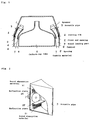
- Fig. 1 is a plan sectional view of a television receiver incorporating a first embodiment of a speaker apparatus according to the invention.
- Fig. 2 is a partially magnified perspective view relating to the speaker and acoustic pipe in Fig. 1.
- Fig. 3 is a perspective view of a television receiver incorporating a second embodiment of a speaker apparatus according to the invention.
- Fig. 4 is a magnified view around a bass-reflex port for enhancing the bass register in Fig. 3.
- Fig. 5 is a comparative diagram of sound pressure and frequency characteristics of the second embodiment and the prior art.
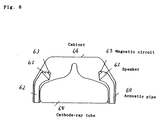
- Fig. 6 is a plan sectional view of a television receiver incorporating a third embodiment of a speaker apparatus according to the invention.
- Fig. 7 is a sectional view showing the constitution of the speaker in Fig. 6.
- Fig. 8 is a sectional view of a magnetic circuit of the speaker in Fig. 7.
- FIG. 1 The diagram shows a plan sectional view of a television receiver incorporating a first embodiment of a speaker apparatus according to the invention.
- a speaker 1 for radiating sound waves provided with an acoustic pipe 3 for guiding the sound waves toward the front end opening 2.
- the television receiver is represented, for the sake of simplicity of drawing, by a television cabinet 4 and a cathode-ray tube 5 disposed at its front side.
- the acoustic pipe 3 is joined to the television cabinet 4 near the front end opening 2 with the front end opening 2 disposed as being suited to the shape of the space enclosed by the outer wall of a cathod-ray tube and the inner wall of a cabinet, by a fitting rib 6, and a cushion material 7 is provided against the cathode-ray tube 5 as buffer means.
- a sound leading part 8 makes use of the hollow space between the television cabinet 4 and cathode-ray tube 5, and an opening 9 for the television receiver is provided at the front side.
- Fig. 2 This is a partly magnified view of the portion relating to the speaker 1 and acoustic pipe 3 in Fig. 1, and a sound absorption material 21 and a reflection plate 22 are shown.
- the speaker apparatus of the invention as shown in Fig. 1 and Fig. 2, even in the television receiver having a slim opening 9 at the front surface of the receiver, since the hollow space surrounded by the cabinet 4 and cathode-ray tube 5 is utilized as the sound leading part 8 for guiding the sound waves radiated from the front end opening 2 of the acoustic pipe 3, the area of the opening 9 at the front face of the television receiver can be widened so that the sound waves may be distributed easily, and the sound quality of the speaker apparatus is enhanced, while the breadth of the television receiver may be made slimmer.
- the sound absorbing material 21 and reflection plate 22 provided inside the acoustic pipe 3 can be disposed in consideration of the length of the sound leading part 8 and the internal structure of the acoustic pipe 3, and it is constituted to prevent propagation of sound waves along the outer wall of the cathode-ray tube 5 by disposing the cushion material 7 at the abutting areas of the front end opening 2 of the acoustic pipe 3 and the outer wall side of the cathode-ray tube 5, also to prevent propagation of sound waves along the inner wall of the cabinet 4 by joining the front end opening 2 of the acoustic pipe 3 and the inner wall side of the cabinet 4 through a fitting rib 6.
- the junction by this fitting rib 6 acts to strengthen the rigidity of the cabinet 4, and the sound quality of the speaker apparatus may be further enhanced.
- the sectional area of the sound leading part 8 is designed larger than the sectional area of the front end opening 2 of the acoustic pipe 3, and therefore the attenuation of sound waves radiated from the speaker 1 through the acoustic pipe 3 is very small, which also contributes to realization of high sound quality.
- the acoustic pipe having a slender opening and a nearly rectangular section for guiding the sound waves is disposed at the front side of the speaker, the front end opening of the acoustic pipe is joined to the outer wall side of the cathode-ray tube and the inner wall side of the cabinet, and a large hollow part enclosed by the outer wall side of the cathode-ray tube and the inner side wall of the cabinet from the junction to the front opening of the cabinet is used as the bass register sound leading part of sound waves, so that the television receiver may be further reduced in size and thickness, while acoustic reproduction of high sound quality and high sound pressure is realized.
- FIG. 3 This is a perspective view of a second embodiment of a speaker apparatus according to the invention.
- an acoustic pipe 33 having a slender and nearly rectangular opening 32 for guiding sound waves is disposed at the front side of a speaker 31 for radiating sound waves.
- a bass-reflex port 35 for enhancing the bass register having an opening 34 is disposed closely to one side of the rectangular side wall for composing the acoustic pipe 33.
- the acoustic pipe 33 and the bass-reflex port 35 for enhancing the bass register are coupled together by means of a wall 36 shared by the both, and a sound absorption material 37 for forming the remaining portion of the wall of the bass-reflex port 35 for enhancing the bass register. That is, at least part of the wall for composing the bass-reflex port is made of sound absurption material.
- a sound absorption material 38 is disposed, and a reflection plate 39 is also provided.
- a tweeter 40 for reproducing the treble register is provided in the sound wave passing route of the speaker 31.
- FIG. 4. This is a magnified view near the bass-reflex port 35 for enhancing the bass register shown in Fig. 3.
- FIG. 5 This is a comparative diagram of the sound pressure and frequency characteristics of the second embodiment of the speaker apparatus of the invention and the speaker apparatus employing the conventional acoustic pipe, in which the characteristic curve a denotes the conventional speaker apparatus, and the characteristic curve b represents the invention.
- the opening of the acoustic pipe is a slender rectangular form, and the opening of the bass-reflex port for enhancing the bass register is disposed closely to the opening of the acoustic pipe.
- the sound waves radiated from the bass-reflex port for enhancing the bass register contain not only low frequency components but also medium and high frequency components. Since the phase relation with the medium and high frequency components radiated from the opening of the acoustic pipe is not constant, enhancing and canceling of the synthesized sound pressure of the both occur, and a sound pressure and frequency characteristic extreme in the difference between the peak and dip as indicated by characteristic curve a in Fig. 5 occurs.
- the sound absorption material 37 disposed near the front opening of the bass-reflex port 35 for enhancing the bass register acts to eliminate the stationary waves occurring inside the acoustic pipe 33, and absorb the medium and high frequency components radiated from the bass-reflex report for enhancing the bass register, and hence there is no interference to the medium and high frequency components radiated from the opening 32 of the acoustic pipe 33, so that a flat sound pressure-frequency characteristic as in characteristic curve b in Fig. 5 is obtained.
- the sound absorption material 37 also acts to remove stationary waves inside the acoustic pipe 33, and therefore the more natural acoustic reproduction which was extremely difficult in the conventional apparatus is realized without attenuating the low frequency components radiated from the bass-reflex port 35 for enhancing the bass register.
- the bass-reflex port 35 for enhancing the bass register is composed of the same wall surface as the wall surface of the acoustic pipe 33, but same effects are obtained by composing to dispose the bass-reflex port 35 for enhancing the bass register closely to the acoustic pipe 33.
- the bass-reflex port 35 for enhancing the bass register is disposed at one side of the acoustic pipe 33, but similar effects can be achieved when disposing the bass-reflex port 35 for enhancing the bass register at both sides of the acoustic pipe 33.
- the acoustic pipe having a nearly rectangular section for guiding the sound waves is disposed, and part of the wall of the bass-reflex port for enhancing the bass register disposed closely to one side or both sides of the wall of the acoustic pipe by using a sound absorption material, so that the television receiver may be further reduced in size and thickness, while acoustic reproduction of high sound quality and high sound pressure is realized.
- FIG. 6 This is a plan sectional view showing the outline of a television receiver incorporating a third embodiment of a speaker apparatus according to the invention.
- a speaker 61 for radiating sound waves at the front side of a speaker 61 for radiating sound waves, an acoustic pipe 62 having a slender and nearly rectangular opening for guiding sound waves is disposed.
- the speaker 61 has a magnetic circuit 63 which is an important element.
- the television receiver is represented by a cabinet 64 and a cathode-ray tube 65 for the sake of simplicity.
- Fig. 7 is a sectional view showing the construction of the speaker 61.
- the magnetic circuit 63 is composed of a columnar center pole 71, a plate 72 mounting the center pole 71 in the middle of the yoke of the bottom, a ring-shaped magnet 73 mounted at the inner side of the upper part of the plate 72, and a magnetic gap 74.
- a frame 75 is fixed on the magnetic circuit 63, and in the open peripheral part of the frame 75 there is affixed the outer circumference of a diaphragm 77 having a voice coil 76 moving up and down without contact in the magnetic tape 74 coupled in the central part.
- the voice coil 76 is supported by a damper 78, and a dust cap 79 is adhered to the diaphragm 77 above the voice coil 76.
- Fig. 8 is a sectional view of the magnetic circuit 63, showing the line of magnetic force of the magnet 73 magnetized in the radial direction, and a leakage magnetic flux 82.
- the line of magnetic force of the magnet 73 passes through the magnetic gap 74 while hardly escaping outside.
- the speaker 61 is composed by forming the magnetic circuit 63 greatly reducing the leakage magnetic flux 82 by using the ring-shaped magnet 73, magnetized in the radial direction, and the acoustic pipe 62 having a slender opening and rectangular form for guiding the sound waves is coupled to the speaker 61, and is disposed closer to the cathode-ray tube 65 of the television receiver, and this is made possible by the fact that the effect of the leakage magnetic flux 82 from the magnetic circuit 63 on the cathode-ray tube 65 can be practically ignored. Therefore, by using the speaker apparatus according to the invention, the receiver is slimmer, and it is also possible to mount on a Hi-Vision receiver of an extended screen with a large aspect ratio, and Hi-Vision receiver of high sound quality and high grade can be presented.
- the constitution of the magnetic circuit 63 is simple, and the shield cover for prevention of leakage magnetic flux is not needed, thereby contributing to reduction of weight.
Landscapes
- Engineering & Computer Science (AREA)
- Multimedia (AREA)
- Signal Processing (AREA)
- Details Of Audible-Bandwidth Transducers (AREA)
- Obtaining Desirable Characteristics In Audible-Bandwidth Transducers (AREA)
Priority Applications (1)
| Application Number | Priority Date | Filing Date | Title |
|---|---|---|---|
| EP96113700A EP0748116B1 (de) | 1992-11-18 | 1993-11-16 | Fernsehempfänger |
Applications Claiming Priority (9)
| Application Number | Priority Date | Filing Date | Title |
|---|---|---|---|
| JP30858792A JP3239485B2 (ja) | 1992-11-18 | 1992-11-18 | スピーカ装置およびそれを用いたテレビジョン受像機 |
| JP308586/92 | 1992-11-18 | ||
| JP4308586A JPH06165280A (ja) | 1992-11-18 | 1992-11-18 | スピーカ装置およびそれを用いたテレビジョン受像機 |
| JP30858792 | 1992-11-18 | ||
| JP308587/92 | 1992-11-18 | ||
| JP30858692 | 1992-11-18 | ||
| JP2099293 | 1993-02-09 | ||
| JP20992/93 | 1993-02-09 | ||
| JP02099293A JP3331657B2 (ja) | 1993-02-09 | 1993-02-09 | スピーカ装置およびそれを用いたテレビジョン受像機 |
Related Child Applications (1)
| Application Number | Title | Priority Date | Filing Date |
|---|---|---|---|
| EP96113700A Division EP0748116B1 (de) | 1992-11-18 | 1993-11-16 | Fernsehempfänger |
Publications (3)
| Publication Number | Publication Date |
|---|---|
| EP0598391A2 true EP0598391A2 (de) | 1994-05-25 |
| EP0598391A3 EP0598391A3 (de) | 1995-03-08 |
| EP0598391B1 EP0598391B1 (de) | 2001-02-07 |
Family
ID=27283249
Family Applications (2)
| Application Number | Title | Priority Date | Filing Date |
|---|---|---|---|
| EP96113700A Expired - Lifetime EP0748116B1 (de) | 1992-11-18 | 1993-11-16 | Fernsehempfänger |
| EP93118507A Expired - Lifetime EP0598391B1 (de) | 1992-11-18 | 1993-11-16 | Fernsehempfänger |
Family Applications Before (1)
| Application Number | Title | Priority Date | Filing Date |
|---|---|---|---|
| EP96113700A Expired - Lifetime EP0748116B1 (de) | 1992-11-18 | 1993-11-16 | Fernsehempfänger |
Country Status (5)
| Country | Link |
|---|---|
| US (1) | US5455867A (de) |
| EP (2) | EP0748116B1 (de) |
| KR (1) | KR0126896B1 (de) |
| CN (1) | CN1050491C (de) |
| DE (2) | DE69329918T2 (de) |
Cited By (9)
| Publication number | Priority date | Publication date | Assignee | Title |
|---|---|---|---|---|
| EP0700210A3 (de) * | 1994-08-30 | 1996-03-27 | Toshiba Kk | |
| GB2310559A (en) * | 1996-02-23 | 1997-08-27 | Nokia Mobile Phones Ltd | Loudspeaker housing arrangements |
| GB2317069A (en) * | 1996-09-06 | 1998-03-11 | Lg Electronics Inc | Loudspeaker system structure for video appliance |
| WO1999062293A1 (en) * | 1998-05-28 | 1999-12-02 | Matsushita Electric Industrial Co., Ltd. | Speaker apparatus and television set |
| EP1039748A3 (de) * | 1999-03-26 | 2001-02-14 | Aiwa Co., Ltd. | Fernsehempfänger |
| US6335974B1 (en) * | 1997-03-19 | 2002-01-01 | Sony Corporation | Speaker system for television receiver with sound ducts and perforated panels |
| EP1318675A3 (de) * | 2001-12-07 | 2004-04-21 | Sony Corporation | Anzeigegerät |
| WO2004047434A1 (en) * | 2002-11-15 | 2004-06-03 | Koninklijke Philips Electronics N.V. | Device having at least one loudspeaker and at least one coil |
| WO2010096230A1 (en) * | 2009-02-19 | 2010-08-26 | Bose Corporation | Acoustic waveguide mechanical vibration damping |
Families Citing this family (10)
| Publication number | Priority date | Publication date | Assignee | Title |
|---|---|---|---|---|
| KR100195535B1 (ko) * | 1995-11-06 | 1999-06-15 | 구자홍 | 영상표시기기의 화면 떨림 방지 장치 |
| US5631449A (en) * | 1995-11-13 | 1997-05-20 | Delta Electronics, Inc. | Audio transmission device for mounting in a monitor of a computer system |
| US5822443A (en) * | 1996-04-22 | 1998-10-13 | Samsung Electronics Co., Ltd. | Speaker system for a television |
| KR100188281B1 (ko) * | 1996-04-22 | 1999-06-01 | 윤종용 | 텔레비젼용 스피커 시스템 |
| CN103957495A (zh) * | 2014-04-30 | 2014-07-30 | 郑润柏 | 一种基于环轴导相管应用的音箱结构 |
| CN111405418B (zh) | 2014-09-30 | 2022-11-04 | 苹果公司 | 具有减小的由来自表面的反射导致的音频染色的扬声器 |
| USRE49437E1 (en) | 2014-09-30 | 2023-02-28 | Apple Inc. | Audio driver and power supply unit architecture |
| CN106162458A (zh) * | 2016-07-19 | 2016-11-23 | 南京大学 | 一种扬声器声传导腔体装置 |
| US10911863B2 (en) | 2016-09-23 | 2021-02-02 | Apple Inc. | Illuminated user interface architecture |
| US10631071B2 (en) | 2016-09-23 | 2020-04-21 | Apple Inc. | Cantilevered foot for electronic device |
Family Cites Families (5)
| Publication number | Priority date | Publication date | Assignee | Title |
|---|---|---|---|---|
| JPS542647Y2 (de) * | 1971-03-10 | 1979-02-05 | ||
| JPS6449500A (en) * | 1987-08-20 | 1989-02-23 | Victor Company Of Japan | Magnetic circuit |
| EP0361445A3 (de) * | 1988-09-28 | 1991-05-22 | Yamaha Corporation | Akustisches Gerät |
| JPH0324900A (ja) * | 1989-06-21 | 1991-02-01 | Onkyo Corp | スピーカ装置 |
| US5229555A (en) * | 1990-03-30 | 1993-07-20 | Matsushita Electric Industrial Co., Ltd. | Speaker system and tv with the same |
-
1993
- 1993-11-16 DE DE69329918T patent/DE69329918T2/de not_active Expired - Fee Related
- 1993-11-16 DE DE69329925T patent/DE69329925T2/de not_active Expired - Fee Related
- 1993-11-16 EP EP96113700A patent/EP0748116B1/de not_active Expired - Lifetime
- 1993-11-16 EP EP93118507A patent/EP0598391B1/de not_active Expired - Lifetime
- 1993-11-17 KR KR1019930024434A patent/KR0126896B1/ko not_active Expired - Fee Related
- 1993-11-17 US US08/153,186 patent/US5455867A/en not_active Expired - Fee Related
- 1993-11-18 CN CN93115069A patent/CN1050491C/zh not_active Expired - Fee Related
Cited By (16)
| Publication number | Priority date | Publication date | Assignee | Title |
|---|---|---|---|---|
| US5710394A (en) * | 1994-08-30 | 1998-01-20 | Kabushiki Kaisha Toshiba | Television set speaker system |
| EP0700210A3 (de) * | 1994-08-30 | 1996-03-27 | Toshiba Kk | |
| GB2310559B (en) * | 1996-02-23 | 2000-09-20 | Nokia Mobile Phones Ltd | Audio output apparatus for a mobile communication device |
| GB2310559A (en) * | 1996-02-23 | 1997-08-27 | Nokia Mobile Phones Ltd | Loudspeaker housing arrangements |
| GB2317069A (en) * | 1996-09-06 | 1998-03-11 | Lg Electronics Inc | Loudspeaker system structure for video appliance |
| GB2317069B (en) * | 1996-09-06 | 1999-04-07 | Lg Electronics Inc | Dome loudspeaker system structure for video appliance |
| US6335974B1 (en) * | 1997-03-19 | 2002-01-01 | Sony Corporation | Speaker system for television receiver with sound ducts and perforated panels |
| WO1999062293A1 (en) * | 1998-05-28 | 1999-12-02 | Matsushita Electric Industrial Co., Ltd. | Speaker apparatus and television set |
| AU753686B2 (en) * | 1998-05-28 | 2002-10-24 | Matsushita Electric Industrial Co., Ltd. | Speaker apparatus and television set |
| US6519348B1 (en) | 1998-05-28 | 2003-02-11 | Matsushita Electric Industrial Co., Ltd. | Speaker apparatus and television set |
| EP1039748A3 (de) * | 1999-03-26 | 2001-02-14 | Aiwa Co., Ltd. | Fernsehempfänger |
| EP1318675A3 (de) * | 2001-12-07 | 2004-04-21 | Sony Corporation | Anzeigegerät |
| US6807051B2 (en) | 2001-12-07 | 2004-10-19 | Sony Corporation | Display apparatus |
| WO2004047434A1 (en) * | 2002-11-15 | 2004-06-03 | Koninklijke Philips Electronics N.V. | Device having at least one loudspeaker and at least one coil |
| WO2010096230A1 (en) * | 2009-02-19 | 2010-08-26 | Bose Corporation | Acoustic waveguide mechanical vibration damping |
| US8002078B2 (en) | 2009-02-19 | 2011-08-23 | Bose Corporation | Acoustic waveguide vibration damping |
Also Published As
| Publication number | Publication date |
|---|---|
| US5455867A (en) | 1995-10-03 |
| KR0126896B1 (ko) | 1997-12-29 |
| DE69329918T2 (de) | 2001-05-31 |
| EP0748116B1 (de) | 2001-02-07 |
| CN1050491C (zh) | 2000-03-15 |
| CN1089772A (zh) | 1994-07-20 |
| EP0748116A1 (de) | 1996-12-11 |
| DE69329925T2 (de) | 2001-05-31 |
| KR940013187A (ko) | 1994-06-25 |
| EP0598391B1 (de) | 2001-02-07 |
| EP0598391A3 (de) | 1995-03-08 |
| DE69329918D1 (de) | 2001-03-15 |
| DE69329925D1 (de) | 2001-03-15 |
Similar Documents
| Publication | Publication Date | Title |
|---|---|---|
| US5455867A (en) | Speaker apparatus and television receiver using the same | |
| EP1206162B1 (de) | Lautsprechergerät | |
| US6335974B1 (en) | Speaker system for television receiver with sound ducts and perforated panels | |
| JP2683128B2 (ja) | テレビジヨン受信機用受動スピーカボツクス | |
| US6205229B1 (en) | Television having a device for preventing vibration of speaker | |
| JP3063214B2 (ja) | スピーカ装置およびそれを用いたテレビジョン受像機 | |
| JPS59183581A (ja) | スピ−カシステム | |
| JPH1098789A (ja) | スピーカ装置 | |
| JPH0879886A (ja) | ダンパレススピーカ | |
| JPH06165280A (ja) | スピーカ装置およびそれを用いたテレビジョン受像機 | |
| JP3123103B2 (ja) | スピーカ装置 | |
| JPH11150775A (ja) | スピーカ装置およびこれを用いたテレビジョン受像機 | |
| KR200217562Y1 (ko) | 텔레비전용스피커장치 | |
| CA2483437C (en) | Speaker apparatus | |
| JPH06217391A (ja) | スピーカ装置 | |
| KR200194908Y1 (ko) | 스피커의 캐비넷 구조 | |
| JP3331657B2 (ja) | スピーカ装置およびそれを用いたテレビジョン受像機 | |
| JPH08107594A (ja) | スピーカ装置 | |
| JP3125519B2 (ja) | スピーカ | |
| JPH1066182A (ja) | スピーカ装置 | |
| JPH0728457B2 (ja) | スピーカ装置およびそれを用いたテレビジョン受像機 | |
| JPH06165276A (ja) | スピーカ装置およびそれを用いたテレビジョン受像機 | |
| JPH0837693A (ja) | スピーカ装置およびそれを用いたテレビジョン受像機 | |
| JPH04165798A (ja) | スピーカ装置およびそれを用いたテレビジョン受像機 | |
| JPH10322790A (ja) | スピーカ |
Legal Events
| Date | Code | Title | Description |
|---|---|---|---|
| PUAI | Public reference made under article 153(3) epc to a published international application that has entered the european phase |
Free format text: ORIGINAL CODE: 0009012 |
|
| AK | Designated contracting states |
Kind code of ref document: A2 Designated state(s): DE GB |
|
| PUAL | Search report despatched |
Free format text: ORIGINAL CODE: 0009013 |
|
| AK | Designated contracting states |
Kind code of ref document: A3 Designated state(s): DE GB |
|
| 17P | Request for examination filed |
Effective date: 19950614 |
|
| 17Q | First examination report despatched |
Effective date: 19960419 |
|
| RTI1 | Title (correction) |
Free format text: TELEVISION RECEIVER |
|
| GRAG | Despatch of communication of intention to grant |
Free format text: ORIGINAL CODE: EPIDOS AGRA |
|
| GRAG | Despatch of communication of intention to grant |
Free format text: ORIGINAL CODE: EPIDOS AGRA |
|
| GRAH | Despatch of communication of intention to grant a patent |
Free format text: ORIGINAL CODE: EPIDOS IGRA |
|
| GRAH | Despatch of communication of intention to grant a patent |
Free format text: ORIGINAL CODE: EPIDOS IGRA |
|
| GRAA | (expected) grant |
Free format text: ORIGINAL CODE: 0009210 |
|
| AK | Designated contracting states |
Kind code of ref document: B1 Designated state(s): DE GB |
|
| XX | Miscellaneous (additional remarks) |
Free format text: TEILANMELDUNG 96113700.7 EINGEREICHT AM 27/08/96. |
|
| REF | Corresponds to: |
Ref document number: 69329918 Country of ref document: DE Date of ref document: 20010315 |
|
| EN | Fr: translation not filed | ||
| PLBE | No opposition filed within time limit |
Free format text: ORIGINAL CODE: 0009261 |
|
| STAA | Information on the status of an ep patent application or granted ep patent |
Free format text: STATUS: NO OPPOSITION FILED WITHIN TIME LIMIT |
|
| REG | Reference to a national code |
Ref country code: GB Ref legal event code: IF02 |
|
| 26N | No opposition filed | ||
| PGFP | Annual fee paid to national office [announced via postgrant information from national office to epo] |
Ref country code: DE Payment date: 20061109 Year of fee payment: 14 |
|
| PGFP | Annual fee paid to national office [announced via postgrant information from national office to epo] |
Ref country code: GB Payment date: 20061115 Year of fee payment: 14 |
|
| GBPC | Gb: european patent ceased through non-payment of renewal fee |
Effective date: 20071116 |
|
| PG25 | Lapsed in a contracting state [announced via postgrant information from national office to epo] |
Ref country code: DE Free format text: LAPSE BECAUSE OF NON-PAYMENT OF DUE FEES Effective date: 20080603 |
|
| PG25 | Lapsed in a contracting state [announced via postgrant information from national office to epo] |
Ref country code: GB Free format text: LAPSE BECAUSE OF NON-PAYMENT OF DUE FEES Effective date: 20071116 |