EP0598800B1 - Enveloppe et enveloppement pour des composants a fibre optique - Google Patents
Enveloppe et enveloppement pour des composants a fibre optique Download PDFInfo
- Publication number
- EP0598800B1 EP0598800B1 EP92917534A EP92917534A EP0598800B1 EP 0598800 B1 EP0598800 B1 EP 0598800B1 EP 92917534 A EP92917534 A EP 92917534A EP 92917534 A EP92917534 A EP 92917534A EP 0598800 B1 EP0598800 B1 EP 0598800B1
- Authority
- EP
- European Patent Office
- Prior art keywords
- inner housing
- sheet
- fibre optic
- housing
- flexible material
- Prior art date
- Legal status (The legal status is an assumption and is not a legal conclusion. Google has not performed a legal analysis and makes no representation as to the accuracy of the status listed.)
- Expired - Lifetime
Links
Images


Classifications
-
- G—PHYSICS
- G02—OPTICS
- G02B—OPTICAL ELEMENTS, SYSTEMS OR APPARATUS
- G02B6/00—Light guides; Structural details of arrangements comprising light guides and other optical elements, e.g. couplings
- G02B6/24—Coupling light guides
- G02B6/26—Optical coupling means
- G02B6/28—Optical coupling means having data bus means, i.e. plural waveguides interconnected and providing an inherently bidirectional system by mixing and splitting signals
- G02B6/2804—Optical coupling means having data bus means, i.e. plural waveguides interconnected and providing an inherently bidirectional system by mixing and splitting signals forming multipart couplers without wavelength selective elements, e.g. "T" couplers, star couplers
- G02B6/2821—Optical coupling means having data bus means, i.e. plural waveguides interconnected and providing an inherently bidirectional system by mixing and splitting signals forming multipart couplers without wavelength selective elements, e.g. "T" couplers, star couplers using lateral coupling between contiguous fibres to split or combine optical signals
- G02B6/2835—Optical coupling means having data bus means, i.e. plural waveguides interconnected and providing an inherently bidirectional system by mixing and splitting signals forming multipart couplers without wavelength selective elements, e.g. "T" couplers, star couplers using lateral coupling between contiguous fibres to split or combine optical signals formed or shaped by thermal treatment, e.g. couplers
-
- G—PHYSICS
- G02—OPTICS
- G02B—OPTICAL ELEMENTS, SYSTEMS OR APPARATUS
- G02B6/00—Light guides; Structural details of arrangements comprising light guides and other optical elements, e.g. couplings
- G02B6/24—Coupling light guides
- G02B6/36—Mechanical coupling means
-
- G—PHYSICS
- G02—OPTICS
- G02B—OPTICAL ELEMENTS, SYSTEMS OR APPARATUS
- G02B6/00—Light guides; Structural details of arrangements comprising light guides and other optical elements, e.g. couplings
- G02B6/24—Coupling light guides
- G02B6/36—Mechanical coupling means
- G02B6/3628—Mechanical coupling means for mounting fibres to supporting carriers
- G02B6/3632—Mechanical coupling means for mounting fibres to supporting carriers characterised by the cross-sectional shape of the mechanical coupling means
- G02B6/3636—Mechanical coupling means for mounting fibres to supporting carriers characterised by the cross-sectional shape of the mechanical coupling means the mechanical coupling means being grooves
Definitions
- This invention relates to the packaging of fibre optic components.
- the invention is described herein with particular reference to the packaging of optical fibre couplers but it will be readily appreciated that the principles of the invention are readily applicable to the packaging of any fibre optic component.
- Optical fibre couplers are presently supplied in a package which is designed both to physically protect the component and to prevent the ingress of moisture and other contaminants to the component.
- the coupler is disposed in an inner cylindrical housing formed of two half silica tubes which are machined to tight dimensional tolerances. These half tubes are brought together and attached together with adhesive.
- the resultant capsule includes respective adhesive deposits which serve to anchor the optical fibre component to the inner surface of the capsule and to seal the ends through which the fibres extend. Additional adhesive may be applied to the ends of the capsule to stabilise the fibres over a wide temperature range.
- the capsule is placed within a stainless steel outer casing which is in turn filled with an elastomer compound. The stainless steel outer casing is provided to give additional strength and protection to the optical component assembly.
- Optical fibre couplers are required to have lifetimes approaching 40 years and to withstand extensive environmental variations. Even though the silica capsule is sealed with adhesive, it has been found through intensive simulated environmental testing that these adhesives are not consistently impervious to moisture over extended periods of time. Test samples have been detected where moisture has ingressed the capsule and affected coupler performance.
- the invention provides a fibre optic component package comprising:
- the invention further provides, in another aspect, a method of packaging a fibre optic component comprising:
- the sheet is preferably a metal foil of any suitably compliant metal, for example tin, nickel, gold, aluminium, monel or an appropriate alloy.
- the foil is advantageously of a thickness in the range 0.01 to 50 micron.
- the foil is preferably wrapped about the inner housing so as to be overlapped longitudinally of the housing.
- the inner housing may be of generally tubular form, e.g. a capsule formed from two half tubes of silica or other appropriate material.
- Adhesive means is preferably provided to maintain the housing and optical fibres as an assembly. Where the inner housing is a tube, this adhesive means preferably includes adhesive deposits to seal the ends of the tube.
- the package may further comprise an outer casing, e.g. a tubular casing, of material such as stainless steel, selected to provide physical protection for the package.
- an outer casing e.g. a tubular casing, of material such as stainless steel, selected to provide physical protection for the package.
- the assembly of the inner housing and the surrounding moisture impervious layer may be retained in the casing in a suitable filling such as silicone elastomer.
- the sealant adhesive is preferably an epoxy compound.
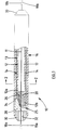
- the illustrated fibre optic component package 10 includes the component itself 11, an inner housing 12 for supporting the component comprising an elongate tubular capsule of silica, a substantially moisture impervious layer 13 including a metal foil wrap 14 providing a sheet of flexible material about housing 12, and an outer casing 16.
- Component 11 may be a fused biconical taper fibre optic coupler and respective pairs of optical fibres 18a, 19a and 18b, 19b then extend from the ends of package 10.
- Inner housing or capsule 12 is formed of two half tubes 12a, 12b of silica glass which are butted at their longitudinal edges and glued along these edges to form a tubular enclosure 17 for the coupler.
- Silica half tube 12b is slightly longer than half tube 12a and respective deposits of adhesive 20 at the ends of half tube 12b locate fibres 18, 19, and therefore coupler 11, centrally of the capsule.
- Adhesive deposits 20 also seal the ends of the capsule and provide additional adhesion between the two halves.
- Capsule 12 is typically formed in a final step on the coupler production machine: the two half tubes, with adhesive along their edges, are brought together about a new coupler and the adhesive deposits 20 applied while the fibres 18, 19 are positioned under tension by adjustable clamp devices. The adhesive is cured before the coupler is removed for further processing.
- Foil wrap 14 is substantially moisture impervious and is typically of thickness about 10 to 30 micron, for example 25 micron, and preferably in the range 0.01 to 50 micron.
- the foil may be formed of any suitably compliant metal, for example tin, nickel, gold, aluminium, monel or an appropriate alloy.
- the foil is circumferentially overlapped at 15 ( Figure 2).
- the overlapped portion is sealed by a suitable sealant such as epoxy which may also serve to bond the foil to the inner housing 12.
- Moisture ingress at the ends of the tubular wrap, defined by edge 25, is resisted by the disposition of sealant epoxy in the region 26.
- the epoxy compound preferably bonds to the foil 14, housing 12 and adhesive deposits 20.
- the package 10 is completed by a filling 28 of a low shear strength silicone elastomer within sleeve 16, according to known practice, and by suitable end caps 30 defining ports 32 for the fibres.
- the metal selected for foil 14 should not have a galvanic action with the material of sleeve 16 as, over extended periods of time, water may then penetrate the sleeve.
- Sleeve 16 may be stainless steel or other suitable material. If sleeve 16 is stainless steel, a suitable material for the foil 14 is tin.
- the capsule 12 might be transported from the coupler production machine and first painted along its exterior cylindrical surfaces with the selected epoxy compound.
- the painted capsule might then be placed in foil 14' folded into a U-section in a groove 42 of a wrapping form 40, with one side of the foil projecting slightly higher than the other.
- Two moving wedges (not shown) would then wrap first the short side and then the long side of the foil onto the painted capsule to complete wrap 14. Excess epoxy compound would be squeezed into the overlap region at the completion of the wrap.
- end fillings 26 might be provided by applying additional epoxy compound to each end of the wrap either before or after completion of folding.
- the selected epoxy compound may be applied to the inner surface of the foil before wrapping.
- the preferred arrangement is that at least a portion of the sealant adhesive is wrapped by the foil and that the sealant adhesive serves to bond the foil 14 and to provide a barrier against moisture ingress to the fibre optic component 11.
- the epoxy compound fills at least those regions at edges of the foil, for example, at the respective axial ends of the wrap and at the region 15 ( Figure 2) where the longitudinal edges overlap.
- the epoxy compound substantially fills the enclosed volume between the foil wrap and housing 12, ie forms a thin layer between the foil wrap and housing 12.
- the package On the completion of wrapping, the package would be removed from the form and placed in an oven for thermal curing of the epoxy compound.
- the wrapped capsule is placed in stainless steel sleeve 16, which is then filled with silicone elastomer in the known manner, and provided with end caps 30.
- the illustrated package arrangement provides a significant improvement in sealing of the inner silica capsule 12 without unacceptably adding to the manufacturing cost of the package, and without significantly increasing its weight. This is achieved without risking problems with thermal coefficient mis-matches: thermal expansion will not be a problem as the metal foil is a very thin metal layer and will be constrained by the much larger mass of the silica capsule.
- the arrangement provides full epoxy/metal protection around the sealed capsule and allows the metal foil to be added to the silica capsule in a wrapping action which avoids the retention of air bubbles, which would not be the case if a metal tube was brought about the capsule.
- water vapour will need to penetrate reasonable lengths of epoxy material 26 before even reaching the innermost housing 12 which in itself is sealed.
- the metal foil wrap 14, and its manner of application, is such that any small holes in the adhesive at the longitudinal butt joins between the half tubes 12a, 12b will be sealed up by the foil and by the added epoxy compound.
- the present applicant has found that, in the long term, such small holes can be the source of moisture breaches.
- the inner housing 12 might not wholly encircle the fibre optic component(s).
Landscapes
- Physics & Mathematics (AREA)
- General Physics & Mathematics (AREA)
- Optics & Photonics (AREA)
- Packaging Of Annular Or Rod-Shaped Articles, Wearing Apparel, Cassettes, Or The Like (AREA)
- Optical Couplings Of Light Guides (AREA)
- Light Guides In General And Applications Therefor (AREA)
- Packages (AREA)
- Wrappers (AREA)
- Optical Fibers, Optical Fiber Cores, And Optical Fiber Bundles (AREA)
Claims (20)
- Emballage (10) de composant de fibre optique comprenantun ou plusieurs composants (11) de fibre optique;un boîtier interne (12) supportant le ou les composant(s), une ou plusieurs fibres optiques (18, 19) associées à ou aux composant(s) s'étendant du boîtier; etune enceinte pour le boîtier interne, l'enceinte comprenanti) une couche (13) qui est substantiellement imperméable à l'humidité y compris à la vapeur d'eau et qui entoure ledit boîtier interne, ladite couche comprenant une feuille (14) en un matériau flexible substantiellement imperméable à l'humidité enveloppée autour du boîtier; etii) un adhésif scellant imperméable à l'humidité qui sert à lier ladite feuille de matériau flexible et qui remplit au moins les régions situées aux bords de ladite feuille aux extrémités axiales de l'enveloppe et dans la région (15) où les bords longitudinaux se chevauchent.
- Emballage de composant de fibre optique selon la revendication 1, dans laquelle ladite feuille de matériau flexible est un feuillard (14) en métal en tout matériau adapté conformé.
- Emballage de composant de fibre optique selon la revendication 2, dans laquelle le feuillard possède une épaisseur située dans la plage de 0.01 à 50 micromètres.
- Emballage de composant de fibre optique selon l'une quelconque des revendications précédentes, dans laquelle ledit boîtier interne (12) est de façon générale allongée et ladite feuille est enveloppée autour du boîtier interne de sorte à être superposée longitudinalement du boîtier.
- Emballage de composant de fibre optique selon l'une quelconque des revendications précédentes dans laquelle ladite feuille (14) d'un matériau flexible enferme un volume autour dudit boîtier interne et ledit adhésif scellant remplit substantiellement ce volume enfermé.
- Emballage de composant de fibre optique selon l'une quelconque des revendications précédentes, dans laquelle ledit adhésif (20) scellant est un composé epoxy.
- Emballage de composant de fibre optique selon l'une quelconque des revendications précédentes, dans laquelle le boîtier (12) interne possède une forme générale tubulaire.
- Emballage de composant de fibre optique selon la revendication 7, dans laquelle le boîtier (12) interne comprend une capsule formée de deux demi-tubes.
- Emballage de composant de fibre optique selon l'une quelconque des revendications précédentes, comprenant en outre des moyens (20) adhésifs maintenant le boîtier et les fibres optiques comme un assemblage, ladite couche s'étendant également autour de tels moyens adhésifs.
- Emballage de composant de fibre optique selon la revendication 9 dans laquelle les moyens adhésifs comprennent des dépôts adhésifs pour sceller les extrémités des tubes.
- Emballage de composant de fibre optique selon l'une quelconque des revendications précédentes, comprenant en outre un carter externe pour fournir une protection physique pour l'emballage.
- Emballage de composant de fibre optique selon la revendication 9 dans laquelle l'assemblage du boîtier interne et de l'enceinte est retenu dans ledit carter dans un matériau de remplissage adapté.
- Procédé pour emballer un composant (11) de fibre optique comprenant :supporter le composant dans un boîtier interne (12), avec une ou plusieurs fibres optiques (18, 19) associées aux composants s'étendant du boîtier; etenfermer ledit boîtier dans une enceinte, ladite enceinte comprenant :une couche (13) qui est substantiellement imperméable à l'humidité y compris à la vapeur d'eau, ladite couche comprenant une feuille (14) d'un matériau flexible substantiellement imperméable à l'humidité enveloppée autour du boîtier; etun adhésif scellant substantiellement imperméable à l'humidité qui sert à lier ladite feuille de matériau flexible et qui remplit au moins les régions (26) au bord de ladite feuille aux extrémités axiales de l'enveloppe et dans la région (15) où des bords longitudinaux se chevauchent.
- Procédé selon la revendication 13, dans lequel ladite étape d'application comprend l'étape consistant à appliquer l'adhésif scellant à l'extérieur du boîtier interne (12) ou à la feuille (14) de matériau flexible substantiellement imperméable à l'humidité, et à envelopper le boîtier interne y compris au moins une portion de l'adhésif scellant appliqué dans Ladite feuille de matériau flexible.
- Procédé selon la revendication 13 ou 14, dans lequel la feuille (14) de matériau flexible est un feuillard métallique de tout métal adapté conformé.
- Procédé selon la revendication 15, dans lequel ledit feuillard possède une épaisseur située dans la plage de 0.01 à 50 micromètres.
- Procédé selon l'une quelconque des revendications 14 à 16, dans lequel ladite feuille de matériau flexible est enveloppée autour du boîtier interne de sorte à être superposé longitudinalement du boîtier.
- Procédé selon l'une quelconque des revendications 13 à 17, dans lequel l'adhésif est utilisé pour maintenir le boîtier et les fibres optiques comme un assemblage.
- Procédé selon l'une quelconque des revendications 13 à 18, comprenant en outre l'étape consistant à enfermer le boîtier interne enveloppé dans un carter extérieur pour fournir une protection physique pour l'emballage.
- Procédé selon la revendication 19 comprenant l'étape consistant à retenir l'assemblage du boîtier interne et de l'enceinte dans ledit carter dans un matériau de remplissage adapté.
Applications Claiming Priority (3)
| Application Number | Priority Date | Filing Date | Title |
|---|---|---|---|
| AU7797/91 | 1991-08-16 | ||
| AUPK779791 | 1991-08-16 | ||
| PCT/AU1992/000425 WO1993004389A1 (fr) | 1991-08-16 | 1992-08-13 | Conditionnement de composants a fibre optique |
Publications (3)
| Publication Number | Publication Date |
|---|---|
| EP0598800A1 EP0598800A1 (fr) | 1994-06-01 |
| EP0598800A4 EP0598800A4 (en) | 1994-08-17 |
| EP0598800B1 true EP0598800B1 (fr) | 1997-07-09 |
Family
ID=3775628
Family Applications (1)
| Application Number | Title | Priority Date | Filing Date |
|---|---|---|---|
| EP92917534A Expired - Lifetime EP0598800B1 (fr) | 1991-08-16 | 1992-08-13 | Enveloppe et enveloppement pour des composants a fibre optique |
Country Status (8)
| Country | Link |
|---|---|
| US (2) | USRE37692E1 (fr) |
| EP (1) | EP0598800B1 (fr) |
| JP (1) | JPH07501407A (fr) |
| AT (1) | ATE155251T1 (fr) |
| AU (1) | AU650365B2 (fr) |
| CA (1) | CA2115545C (fr) |
| DE (1) | DE69220799T2 (fr) |
| WO (1) | WO1993004389A1 (fr) |
Families Citing this family (22)
| Publication number | Priority date | Publication date | Assignee | Title |
|---|---|---|---|---|
| US5533161A (en) * | 1993-11-05 | 1996-07-02 | Honeywell Inc. | Wrap around fiber optic component package and packaging method |
| US6000858A (en) * | 1996-07-12 | 1999-12-14 | Bloom; Cary | Apparatus for, and method of, forming a low stress tight fit of an optical fiber to an external element |
| US5971629A (en) | 1996-07-12 | 1999-10-26 | Bloom; Cary | Apparatus and method bonding optical fiber and/or device to external element using compliant material interface |
| US5805757A (en) * | 1996-12-10 | 1998-09-08 | Bloom; Cary | Apparatus and method for preserving optical characteristics of a fiber optic device |
| US5871559A (en) * | 1996-12-10 | 1999-02-16 | Bloom; Cary | Arrangement for automated fabrication of fiber optic devices |
| US5815619A (en) * | 1996-12-10 | 1998-09-29 | Bloom; Cary | Fiber optic connector hermetically terminated |
| US5948134A (en) * | 1996-09-24 | 1999-09-07 | Bloom; Cary | Apparatus for forming a fiber optic coupler by dynamically adjusting pulling speed and heat intensity |
| US6177985B1 (en) | 1996-10-01 | 2001-01-23 | Cary Bloom | Apparatus and method for testing optical fiber system components |
| US5764348A (en) * | 1996-10-01 | 1998-06-09 | Bloom; Cary | Optical switching assembly for testing fiber optic devices |
| US6003341A (en) | 1996-12-10 | 1999-12-21 | Bloom; Cary | Device for making fiber couplers automatically |
| US5917975A (en) * | 1996-12-10 | 1999-06-29 | Bloom; Cary | Apparatus for, and method of, forming a low stress tight fit of an optical fiber to an external element |
| US6074101A (en) * | 1996-12-10 | 2000-06-13 | Bloom; Cary | Apparatus for, and method of, forming a low stress tight fit of an optical fiber to an external element |
| GB9912746D0 (en) * | 1999-06-01 | 1999-08-04 | Cit Alcatel | A submarine casing |
| US6561701B1 (en) * | 2000-08-11 | 2003-05-13 | Alliance Fiber Optics Products, Inc. | Packaging and sealing of multi-port fiber optic device |
| US6865334B2 (en) * | 2003-06-28 | 2005-03-08 | General Dynamics Advanced Information Systems, Inc. | Termination assembly for use in optical fiber hydrophone array |
| US6934451B2 (en) * | 2003-06-28 | 2005-08-23 | General Dynamics Advanced Information Systems, Inc. | Mount for use in optical fiber hydrophone array |
| US6879545B2 (en) * | 2003-06-28 | 2005-04-12 | General Dynamics Advanced Information Systems, Inc. | Woven fiber protection cable assembly for use in optical fiber hydrophone array |
| US6870997B2 (en) * | 2003-06-28 | 2005-03-22 | General Dynamics Advanced Information Systems, Inc. | Fiber splice tray for use in optical fiber hydrophone array |
| US6904222B2 (en) * | 2003-06-28 | 2005-06-07 | General Dynamics Advanced Information Systems, Inc. | Optical fiber splice protection apparatus for use in optical fiber hydrophone array |
| US7027695B2 (en) * | 2003-06-28 | 2006-04-11 | General Dynamics Advanced Information Systems, Inc. | Fiber transition segment for use in optical fiber hydrophone array |
| WO2006019376A1 (fr) * | 2004-07-16 | 2006-02-23 | Waters Investments Limited | Raccord de tube et procede de soudage de tubes |
| US6974261B1 (en) | 2003-12-22 | 2005-12-13 | Itt Manufacturing Enterprises, Inc. | Optical bonding structure |
Family Cites Families (8)
| Publication number | Priority date | Publication date | Assignee | Title |
|---|---|---|---|---|
| JPS6066211A (ja) * | 1983-09-21 | 1985-04-16 | Nippon Telegr & Teleph Corp <Ntt> | 密閉型保護ケ−ス |
| GB2164469B (en) * | 1984-09-14 | 1988-12-21 | Stc Plc | Optical fibre cables |
| IT1184648B (it) * | 1985-06-26 | 1987-10-28 | Pirelli Cavi Spa | Linea sottomarina per telecomunicazioni a firbre ottiche |
| JPS6290604A (ja) * | 1985-10-17 | 1987-04-25 | Optic Daiichi Denko Co Ltd | 光フアイバケ−ブルの端末処理方法 |
| US4844575A (en) * | 1987-04-10 | 1989-07-04 | American Telephone And Telegraph Company, At&T Bell Laboratories | Optical fiber cable |
| GB2215081B (en) * | 1988-02-11 | 1992-05-20 | Stc Plc | Optical fibre communications cable |
| US5071221A (en) * | 1988-08-05 | 1991-12-10 | Mitsubishi Petrochemical Company Limited | Water penetration preventive cable |
| US5217808A (en) * | 1989-11-29 | 1993-06-08 | At&T Bell Laboratories | Water blocked cable portion and methods of making same |
-
1992
- 1992-08-13 US US09/241,709 patent/USRE37692E1/en not_active Expired - Fee Related
- 1992-08-13 AT AT92917534T patent/ATE155251T1/de not_active IP Right Cessation
- 1992-08-13 DE DE69220799T patent/DE69220799T2/de not_active Expired - Fee Related
- 1992-08-13 AU AU24325/92A patent/AU650365B2/en not_active Ceased
- 1992-08-13 WO PCT/AU1992/000425 patent/WO1993004389A1/fr not_active Ceased
- 1992-08-13 EP EP92917534A patent/EP0598800B1/fr not_active Expired - Lifetime
- 1992-08-13 CA CA002115545A patent/CA2115545C/fr not_active Expired - Fee Related
- 1992-08-13 US US08/193,187 patent/US5602952A/en not_active Ceased
- 1992-08-13 JP JP5503958A patent/JPH07501407A/ja active Pending
Also Published As
| Publication number | Publication date |
|---|---|
| CA2115545A1 (fr) | 1993-03-04 |
| AU650365B2 (en) | 1994-06-16 |
| US5602952A (en) | 1997-02-11 |
| JPH07501407A (ja) | 1995-02-09 |
| USRE37692E1 (en) | 2002-05-07 |
| EP0598800A4 (en) | 1994-08-17 |
| AU2432592A (en) | 1993-03-16 |
| DE69220799D1 (de) | 1997-08-14 |
| EP0598800A1 (fr) | 1994-06-01 |
| DE69220799T2 (de) | 1998-01-29 |
| ATE155251T1 (de) | 1997-07-15 |
| CA2115545C (fr) | 2003-11-18 |
| WO1993004389A1 (fr) | 1993-03-04 |
Similar Documents
| Publication | Publication Date | Title |
|---|---|---|
| EP0598800B1 (fr) | Enveloppe et enveloppement pour des composants a fibre optique | |
| JP2614018B2 (ja) | 光ファイバ導入部の気密封止構造と気密封止方法 | |
| CA2061693C (fr) | Materiau et methode de renforcement de coupleurs optiques | |
| CN103887688B (zh) | 分布反馈光纤激光器的封装结构 | |
| US5970194A (en) | Optical fiber having hermetically sealable section | |
| WO1998026317A1 (fr) | Appareil et procede pour assurer la fixation a faibles contraintes d'une fibre optique a un element externe | |
| US4902091A (en) | Light waveguide feedthrough for optoelectronic modules and method for their manufacture | |
| EP0553606A1 (fr) | Méthode et arrangement pour épissurer des guide d'ondes optiques | |
| CA2404093C (fr) | Dispositif de conditionnement de composants optiques | |
| JP2579648B2 (ja) | 光フアイバーケーブル端子およびその形成方法 | |
| CN105697392A (zh) | 潜油泵作业过程中多参数在线监测控制系统及制作方法 | |
| US5734767A (en) | Fiber optic coupler | |
| JPH0527139A (ja) | 光導波回路モジユール | |
| JPS59135414A (ja) | 光フアイバ結合器のパツケ−ジ装置およびその製造方法 | |
| US6085001A (en) | Fiber optic coupler | |
| JP3085344B2 (ja) | 光モジュール | |
| US5805752A (en) | Environment-proof fiber optic coupler | |
| CN213633905U (zh) | 一种光纤耦合器 | |
| JPH10300969A (ja) | 光ファイバの融着接続部に対する保護体及びその形成方法 | |
| US7083334B2 (en) | Hermetically sealed optical fiber ferrule assembly supporting multiple optical fibers | |
| US20020076175A1 (en) | Packaging for fiber optic devices | |
| US6561701B1 (en) | Packaging and sealing of multi-port fiber optic device | |
| GB2377766A (en) | Optic fibre assembly hermetically sealed in a feedthrough | |
| JP3590126B2 (ja) | ファイバー型光部品の実装構造 | |
| JPH023521Y2 (fr) |
Legal Events
| Date | Code | Title | Description |
|---|---|---|---|
| PUAI | Public reference made under article 153(3) epc to a published international application that has entered the european phase |
Free format text: ORIGINAL CODE: 0009012 |
|
| 17P | Request for examination filed |
Effective date: 19940218 |
|
| AK | Designated contracting states |
Kind code of ref document: A1 Designated state(s): AT BE CH DE DK ES FR GB GR IE IT LI LU MC NL SE |
|
| A4 | Supplementary search report drawn up and despatched | ||
| AK | Designated contracting states |
Kind code of ref document: A4 Designated state(s): AT BE CH DE DK ES FR GB GR IE IT LI LU MC NL SE |
|
| 17Q | First examination report despatched |
Effective date: 19960116 |
|
| GRAG | Despatch of communication of intention to grant |
Free format text: ORIGINAL CODE: EPIDOS AGRA |
|
| GRAH | Despatch of communication of intention to grant a patent |
Free format text: ORIGINAL CODE: EPIDOS IGRA |
|
| GRAH | Despatch of communication of intention to grant a patent |
Free format text: ORIGINAL CODE: EPIDOS IGRA |
|
| GRAA | (expected) grant |
Free format text: ORIGINAL CODE: 0009210 |
|
| AK | Designated contracting states |
Kind code of ref document: B1 Designated state(s): AT BE CH DE DK ES FR GB GR IE IT LI LU MC NL SE |
|
| PG25 | Lapsed in a contracting state [announced via postgrant information from national office to epo] |
Ref country code: NL Free format text: LAPSE BECAUSE OF FAILURE TO SUBMIT A TRANSLATION OF THE DESCRIPTION OR TO PAY THE FEE WITHIN THE PRESCRIBED TIME-LIMIT Effective date: 19970709 Ref country code: LI Free format text: LAPSE BECAUSE OF FAILURE TO SUBMIT A TRANSLATION OF THE DESCRIPTION OR TO PAY THE FEE WITHIN THE PRESCRIBED TIME-LIMIT Effective date: 19970709 Ref country code: IT Free format text: LAPSE BECAUSE OF FAILURE TO SUBMIT A TRANSLATION OF THE DESCRIPTION OR TO PAY THE FEE WITHIN THE PRESCRIBED TIME-LIMIT;WARNING: LAPSES OF ITALIAN PATENTS WITH EFFECTIVE DATE BEFORE 2007 MAY HAVE OCCURRED AT ANY TIME BEFORE 2007. THE CORRECT EFFECTIVE DATE MAY BE DIFFERENT FROM THE ONE RECORDED. Effective date: 19970709 Ref country code: GR Free format text: LAPSE BECAUSE OF FAILURE TO SUBMIT A TRANSLATION OF THE DESCRIPTION OR TO PAY THE FEE WITHIN THE PRESCRIBED TIME-LIMIT Effective date: 19970709 Ref country code: ES Free format text: THE PATENT HAS BEEN ANNULLED BY A DECISION OF A NATIONAL AUTHORITY Effective date: 19970709 Ref country code: DK Effective date: 19970709 Ref country code: CH Free format text: LAPSE BECAUSE OF FAILURE TO SUBMIT A TRANSLATION OF THE DESCRIPTION OR TO PAY THE FEE WITHIN THE PRESCRIBED TIME-LIMIT Effective date: 19970709 Ref country code: BE Effective date: 19970709 Ref country code: AT Effective date: 19970709 |
|
| REF | Corresponds to: |
Ref document number: 155251 Country of ref document: AT Date of ref document: 19970715 Kind code of ref document: T |
|
| REG | Reference to a national code |
Ref country code: CH Ref legal event code: EP |
|
| REF | Corresponds to: |
Ref document number: 69220799 Country of ref document: DE Date of ref document: 19970814 |
|
| PG25 | Lapsed in a contracting state [announced via postgrant information from national office to epo] |
Ref country code: LU Free format text: LAPSE BECAUSE OF NON-PAYMENT OF DUE FEES Effective date: 19970831 |
|
| PG25 | Lapsed in a contracting state [announced via postgrant information from national office to epo] |
Ref country code: IE Free format text: LAPSE BECAUSE OF NON-PAYMENT OF DUE FEES Effective date: 19970909 |
|
| PG25 | Lapsed in a contracting state [announced via postgrant information from national office to epo] |
Ref country code: SE Effective date: 19971009 |
|
| ET | Fr: translation filed | ||
| NLV1 | Nl: lapsed or annulled due to failure to fulfill the requirements of art. 29p and 29m of the patents act | ||
| REG | Reference to a national code |
Ref country code: CH Ref legal event code: PL |
|
| PG25 | Lapsed in a contracting state [announced via postgrant information from national office to epo] |
Ref country code: MC Free format text: LAPSE BECAUSE OF NON-PAYMENT OF DUE FEES Effective date: 19980228 |
|
| PLBE | No opposition filed within time limit |
Free format text: ORIGINAL CODE: 0009261 |
|
| 26N | No opposition filed | ||
| REG | Reference to a national code |
Ref country code: GB Ref legal event code: IF02 |
|
| PGFP | Annual fee paid to national office [announced via postgrant information from national office to epo] |
Ref country code: DE Payment date: 20070809 Year of fee payment: 16 |
|
| PGFP | Annual fee paid to national office [announced via postgrant information from national office to epo] |
Ref country code: GB Payment date: 20070809 Year of fee payment: 16 |
|
| PGFP | Annual fee paid to national office [announced via postgrant information from national office to epo] |
Ref country code: FR Payment date: 20070808 Year of fee payment: 16 |
|
| GBPC | Gb: european patent ceased through non-payment of renewal fee |
Effective date: 20080813 |
|
| REG | Reference to a national code |
Ref country code: FR Ref legal event code: ST Effective date: 20090430 |
|
| PG25 | Lapsed in a contracting state [announced via postgrant information from national office to epo] |
Ref country code: FR Free format text: LAPSE BECAUSE OF NON-PAYMENT OF DUE FEES Effective date: 20080901 Ref country code: DE Free format text: LAPSE BECAUSE OF NON-PAYMENT OF DUE FEES Effective date: 20090303 |
|
| PG25 | Lapsed in a contracting state [announced via postgrant information from national office to epo] |
Ref country code: GB Free format text: LAPSE BECAUSE OF NON-PAYMENT OF DUE FEES Effective date: 20080813 |