EP0599171B1 - Verfahren zur Regelung und/oder Überwachung eines Hydraulikspeichers - Google Patents
Verfahren zur Regelung und/oder Überwachung eines Hydraulikspeichers Download PDFInfo
- Publication number
- EP0599171B1 EP0599171B1 EP93118436A EP93118436A EP0599171B1 EP 0599171 B1 EP0599171 B1 EP 0599171B1 EP 93118436 A EP93118436 A EP 93118436A EP 93118436 A EP93118436 A EP 93118436A EP 0599171 B1 EP0599171 B1 EP 0599171B1
- Authority
- EP
- European Patent Office
- Prior art keywords
- pressure
- piston
- storage means
- gas
- charging
- Prior art date
- Legal status (The legal status is an assumption and is not a legal conclusion. Google has not performed a legal analysis and makes no representation as to the accuracy of the status listed.)
- Expired - Lifetime
Links
- 238000000034 method Methods 0.000 title claims abstract description 25
- 238000012544 monitoring process Methods 0.000 title claims abstract description 17
- 238000004512 die casting Methods 0.000 claims abstract description 25
- 238000003860 storage Methods 0.000 claims description 43
- 238000005266 casting Methods 0.000 claims description 34
- 239000012530 fluid Substances 0.000 claims description 17
- 230000008569 process Effects 0.000 claims description 8
- 238000001746 injection moulding Methods 0.000 claims description 4
- 230000001105 regulatory effect Effects 0.000 claims description 3
- 238000007689 inspection Methods 0.000 claims 1
- 238000012423 maintenance Methods 0.000 claims 1
- 238000003825 pressing Methods 0.000 claims 1
- 238000001514 detection method Methods 0.000 abstract description 2
- 238000002347 injection Methods 0.000 abstract 1
- 239000007924 injection Substances 0.000 abstract 1
- 239000007789 gas Substances 0.000 description 43
- IJGRMHOSHXDMSA-UHFFFAOYSA-N Atomic nitrogen Chemical compound N#N IJGRMHOSHXDMSA-UHFFFAOYSA-N 0.000 description 26
- 229910052757 nitrogen Inorganic materials 0.000 description 13
- 230000015654 memory Effects 0.000 description 6
- 230000008859 change Effects 0.000 description 5
- 230000006870 function Effects 0.000 description 5
- 238000006073 displacement reaction Methods 0.000 description 4
- 238000011156 evaluation Methods 0.000 description 4
- 239000002184 metal Substances 0.000 description 4
- 238000010438 heat treatment Methods 0.000 description 3
- 239000004604 Blowing Agent Substances 0.000 description 2
- 238000010586 diagram Methods 0.000 description 2
- 239000007788 liquid Substances 0.000 description 2
- 229910001338 liquidmetal Inorganic materials 0.000 description 2
- 239000000256 polyoxyethylene sorbitan monolaurate Substances 0.000 description 2
- 239000003380 propellant Substances 0.000 description 2
- 239000000523 sample Substances 0.000 description 2
- 230000001960 triggered effect Effects 0.000 description 2
- 229910000831 Steel Inorganic materials 0.000 description 1
- 230000006835 compression Effects 0.000 description 1
- 238000007906 compression Methods 0.000 description 1
- 230000003247 decreasing effect Effects 0.000 description 1
- 238000005187 foaming Methods 0.000 description 1
- 239000011261 inert gas Substances 0.000 description 1
- 230000007257 malfunction Effects 0.000 description 1
- 238000004519 manufacturing process Methods 0.000 description 1
- 238000005259 measurement Methods 0.000 description 1
- 230000036316 preload Effects 0.000 description 1
- 238000002360 preparation method Methods 0.000 description 1
- 238000000926 separation method Methods 0.000 description 1
- 230000003068 static effect Effects 0.000 description 1
- 239000010959 steel Substances 0.000 description 1
- 230000007704 transition Effects 0.000 description 1
- 230000003936 working memory Effects 0.000 description 1
Images


Classifications
-
- B—PERFORMING OPERATIONS; TRANSPORTING
- B22—CASTING; POWDER METALLURGY
- B22D—CASTING OF METALS; CASTING OF OTHER SUBSTANCES BY THE SAME PROCESSES OR DEVICES
- B22D17/00—Pressure die casting or injection die casting, i.e. casting in which the metal is forced into a mould under high pressure
- B22D17/20—Accessories: Details
- B22D17/32—Controlling equipment
Definitions
- the invention relates to a method for regulation and / or Monitoring a hydraulic accumulator on a die casting or Injection molding machine according to the generic term of Claim 1.
- the casting unit is driven usually through one or more hydraulic accumulators.
- the drive piston moving the casting piston must therefore in the transition from the slow forward phase to rapid mold filling phase can be accelerated.
- This container will Called a pressure accumulator or hydraulic accumulator.
- a such a pressure accumulator consists of a normal version Steel bottle in which an inert gas, in particular Nitrogen is included as a blowing agent.
- the high pressure pump of the machine hydraulics promotes the Hydraulic fluid in the accumulator against the pressure of the trapped gas. This "return promotion” happens until the maximum pressure that can be set on the pump also is reached in memory. Liquid and nitrogen are available under the same pressure, the so-called storage pressure.
- the pressure energy stored in the pressure accumulator is available Opening of the shot valve for driving the drive piston and thus the casting piston. This will turn it off volume of liquid flowing out of the pressure accumulator Nitrogen replaced, d. H. the nitrogen expands and causes a drop in pressure. To reduce this pressure drop in relative to keep narrow limits, one measures those under storage pressure Amount of nitrogen to be kept correspondingly large, which is indicated by a or more additional nitrogen bottles happening on Casting drive attached and connected to the pressure accumulator are.
- the pressure accumulator is usually used for die casting machines built as a so-called piston accumulator.
- piston accumulator separates one Pressure accumulator movable piston the pressurized gas (nitrogen) from the hydraulic fluid. Through this flying piston it is avoided that the nitrogen in the Hydraulic fluid can swirl. Furthermore, one Foaming or a carryover of nitrogen into the Hydraulic system of such as a piston accumulator trained pressure accumulator not possible.
- multipliers are used.
- a Piston ratio achieved an increase in casting pressure.
- the multiplier device can be a separate one Pressure accumulator can be assigned, as is cited in the Literature Brunnhuber (op. Cit.) Is shown on page 75.
- Such a multi-stage pressurization is also from DE PS 20 21 182.
- the state of the accumulator charge of the accumulator is an important factor in the die casting process.
- the Biasing of the respective pressure accumulator by regulating the Maximum pressure on a hydraulic pump can be changed.
- the Position of the piston in the pressure accumulator or piston accumulator determines the hydraulic quantity pumped into the piston accumulator and the compressed gas compressed as a blowing agent.
- This "loading process" of the pressure accumulator can be based on a Charging curve to be tracked by a first Starting position of the piston (pre-charging point) to a second Position of the piston (operating point) runs.
- the invention aims to improve the described Operating conditions. Because the state of the pressure accumulator decisive influence on the quality of the die-cast parts may have the object of the invention, a To improve these settings.
- the method according to the invention aims at regulation and / or monitoring of the pressure accumulator in particular a die casting machine, this principle also on one Injection molding machine is usable.
- a key concept of the invention is that Operating point of the pressure accumulator for a most precise detection or is subjected to monitoring and regulation.
- the Operating point of an accumulator through a series of various influencing variables that are changed in particular by the state of the precharge pressure and the Gas volume can be influenced.
- By changing the Various parameters in the system can also be Change the operating point of the pressure accumulator since it is not is determined solely by the storage pressure of the propellant. For example, the memory pressure alone does not determine reliable the operating point, since this is also crucial by the storage volume or the hydraulic volume or the Position of the piston in the working memory is determined.
- the invention is based on the automatic monitoring and Regulation of the hydraulic accumulator of a die casting machine described.
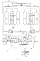
- the casting drive 1 shown in Figure 1 is used for Actuation of a casting set 2, consisting of a Casting chamber 3 with contained metal melt 4 and one Pouring plunger 5 for inserting the molten metal 4 into one mold cavity shown in detail.
- the casting piston 5 is over a casting piston rod 6 connected to the casting drive 1.
- the Casting drive 1 consists of a front press cylinder 7 and a plunger 8 guided therein, which acts as a drive piston 8 serves for the associated piston rod 6.
- the press cylinder 7 has a front cylinder space 9 and a rear Cylinder chamber 10 separated by the plunger 8 are.
- the front cylinder space 9 is with a Print medium connection 11 connected.
- the press cylinder 7 closes one Multiplier device 12, in which an axial displaceable multiplier piston 13 is arranged.
- the multiplier piston 13 divides the associated cylinder space 14 in a front cylinder space 15 and a rear Cylinder chamber 16.
- the multiplier piston 13 has one first piston rod 17 extending towards the casting set 2 which is characterized by the cylinder wall of the Multiplier cylinder housing in the rear cylinder chamber 10 of the press cylinder 7 extends.
- the Multiplierorkn 13 a rear piston rod 18, the also into one via the multiplier cylinder housing rear cylinder space 19 of an additional connection housing 20 extends.
- the multiplier piston 13 with front Piston rod 17 and rear piston rod 18 is replaced by a central longitudinal bore 21 penetrates, in which a Check valve 22 is located.
- Pressure accumulator 23, 24 provided, the so-called Piston accumulator, each with a piston 25 movable therein, 26 are formed. Located below the piston 25, 26 the hydraulic fluid 27, 28, above the respective Piston 25, 26 which is generally designed as nitrogen Pressure medium 29, 30. To increase the gas volume of the pressure medium enlarge, each pressure accumulator 23, 24 are two additional nitrogen bottles 31, 31 'and 32, 32' assigned.
- the pressure accumulator 23 is a Connection line 33 and a control valve 34 with the rear Cylinder chamber 19 of the connection housing 20, the pressure accumulator 24 via the connecting line 35 and a control valve 36 with the rear cylinder chamber 16 of the multiplier cylinder 14 connected.
- the casting piston After the slow advance has ended, the casting piston accelerated at high speed for the mold filling stroke. This is done by a switchover point using a Control cam 41 on the casting piston rod 6. Das The control cam signal is sent to a computer 43 via a line 42 supplied with an output signal or via a line 44 Provides momentum to the shot valve 34. This impulse opens the shot valve 34 so that the hydraulic fluid 27th abruptly from the pressure accumulator 23 into the pressure chamber 19 and thus in the pressure chamber 10 to accelerate the plunger 8 can reach.
- the position of the operating point is for the pressure accumulators 23, 24 for a more detailed explanation in Fig. 2 in an example shown.
- the operating point of a pressure accumulator through different Influencing variables are changed.
- the upper diagram in Fig. 2 is on the abscissa the volume V and on the Ordinate the pressure p of the gaseous pressure medium (Nitrogen) as shown in the cylinder space 29, 30 and the additional tanks 31, 32 in FIG. 1.
- the lower half of the figure in FIG. 2 is the pressure accumulator 23, 24 shown, with a first piston position 25 ', 26' in Pre-charging point 46 and a second piston position 25, 26 in Operating point 47.
- the two points 46, 47 are by the Charging curve 48 connected.
- the piston 25, 26 is located in the precharge point 46 lowest position, d. H. all hydraulic fluid 27, 28 is at the end of the casting process from the respective Printing cylinders 23, 24 have been pressed out.
- the hydraulic fluid 27, 28 must be pumped back into the pressure accumulators 23, 24 so that the pistons 25, 26 move in these pressure accumulators.
- This displacement of the pistons 25, 26 compresses the gas 29, 30 in the exemplary embodiment according to FIG. 2, for example from a volume of 60 liters to a volume of 44 liters, ie 16 liters of hydraulic medium become in the pressure accumulator 23, 24 pressed in.
- This compression of the pressure medium 29, 30 increases the pressure of this gas from the pressure p 0 of z. B. 110 bar to the pressure p B of 150 bar along the charging curve 48.
- the precharge point 46 is therefore characterized by the size V 0 , p 0 , the operating point 47 is characterized by the compressed volume V B and the compressed pressure p B.
- This loading process of the respective pressure accumulator 23, 24 takes place along the loading curve 48 in FIG. 2.
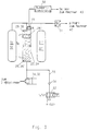
- FIG 3 shows an exemplary embodiment for monitoring or regulating the pressure accumulator 23, 24.
- the position of the separating piston 25, 26 in the pressure accumulator can be measured by means of an ultrasonic displacement sensor 49.
- An analog travel signal s K is available at the output of evaluation electronics 50 and is fed to computer 43.
- the Gas pressure of the pressure medium 29, 30 or the pressure in the Gas bottles 31, 32 measured and this value also the Computer 43 supplied.
- the superordinate computer an evaluation of the exact position of the pressure piston 25, 26 in the operating point 47 or in Precharge point 46 (lower position of the piston 25 ', 26') make.
- the hydraulic valve 52 is for the application the pressure accumulator 23, 24 with pressure medium by means of a Pressure pump 53 shown.
- a check valve 54 in a feed line 55 prevents backflow of the Print medium.
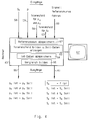
- FIG. 4 An overview of the operation of the computer 43 is in Fig. 4 shown.
- an assignment of the pressure p to the actual value of the piston travel s KIst is stored in the computer 43 each time the hydraulic accumulator is loaded . It makes sense here if the values of the piston travel s K are saved at the same pressures as when the reference data were recorded, ie the actual values of the piston travel s KIst are stored as a function of the pressure, for example in the following table: bar mm p s IS 110 s K (0) 115 s K (1) 120 ⁇ 125 ⁇ etc. 150 s K (n)
- This comparison in the computer is shown in FIG. 4 below arrow 61, ie the computer compares the actual values of the piston travel with corresponding setpoints of the piston travel over the distance of the loading curve. It should be noted that this comparison is made via points 1 to n of the measured values of the charging curve.
- FIG. 4 shows the essential content of the task of the computer 43, the values of the inputs 56 to 60 being recorded.
- the reference data are stored in the computer
- the tolerance fields are formed and target data are generated
- the actual data 64 are stored and in a further step 65 a comparison is made.
- the outputs on the computer are a piston travel curve s K of the separating piston as a function of the pressure (arrow 61) and an actual setpoint comparison of the precharge pressure p 0 at the precharge point 46 (arrow 66).
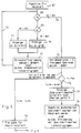
- the restart takes place when the machine is switched on (position 67).
- an actual setpoint comparison of the precharge pressure p 0 is carried out in position 68. If the actual value is not equal to the target value of the precharge pressure (position 69), these values are compared in the computer 43. If P 0 is greater than P 0Soll (position 70), the display 61 shows that p 0 is too large. Likewise, a display is shown on the screen 61 in the case of a comparison P 0 actual less than p 0 set (position 71). Both times, the nitrogen precharge is changed accordingly (position 72 in FIG. 5) or automatic compensation takes place in a separate subroutine.
- This process takes place in a circulation loop 73 until the actual value of the precharge pressure p 0 corresponds to the entered target value, so that the program embarks on the computer path 74 from the starting point 68. In position 75, it is accordingly determined that the precharge pressures p 0 are in order and that the automatic storage tank charging is enabled.
- the piston travel s K of the separating piston 25, 26 is monitored as a function of the gas pressure p V (position 76 in the flowchart).
- s K f (p) ).
- position 77 shows on screen 61 'that the storage bottles 31, 32 are filled, for example, with hydraulic medium due to a leaking separating piston. In this way, the machine is switched off at position 78 to remedy the fault.
- the storage bottles 31, 32 can be emptied from the hydraulic medium manually or by means of an automatic emptying in a subroutine.
- position 79 enables the machine start.
- the monitoring takes place before the casting cycle is triggered after the release for the machine start (position 79).
- position 80 determines whether the mold is closed. Then the pressure accumulator monitoring starts at position 81.
- position 82 it is first checked whether the pressure P B of the operating point 47 is OK. If it is determined in position 83 that the operating point is too small or too large, then in position 84 if the operating point p B is too small, a display is shown on the screen 61 'that the operating point p B is to be increased by a manual change of setting on the die casting machine , or that this pressure p B has to be increased automatically via a subroutine.
- a display on the screen 61 ' is carried out as an error indication that the operating pressure p B can be reduced by a manual change of setting on the die casting machine, which can also be carried out automatically if necessary. This takes place via the computer loop 86 until the operating point is in order, which is indicated under position 87.
- the precharge pressure p 0 is too small, which can be caused by gas loss in the pressure accumulator 29 to 32.
- the cause of gas heating is indicated by reference number 92, the cause of gas loss by reference number 93.
- the mold is opened at position 94, as a result of which the machine start is interrupted and the precharge pressure p 0 is to be changed manually or by means of a subroutine at position 95.
- position 96 releases the metal metering and thus triggers a shot via the shot valves 34, 36.
- FIGS. 7 shows how the precharge pressure p 0 can be automatically set to the correct value.
- the same parts are identified with the same reference numerals as in the previous figures. For this purpose, reference is made in particular to FIGS. 1 and 3.
- Two valves 97, 98 are actuated by means of a control unit (not shown in more detail in FIG. 7) or a control unit connected in parallel to the computer 43.
- a control unit not shown in more detail in FIG. 7
- additional compressed gas is supplied from a transportable compressed gas bottle 99 to the pressure accumulators 23, 24 including the gas bottles 31, 32 via the line 100, the precharge pressure p 0 being able to increase.
- the valve 97 is de-energized by the pressure measuring device 51, so that the access to the pressure bottle 99 is closed.
- the actual value of the precharge pressure p 0 is accordingly measured by means of the pressure sensor 51 with evaluation in the computer 43. This measurement signal is fed to the control device (not shown in more detail) in order to actuate the valve 97.
- the valve 98 is in turn switched off via the control device (not shown) when the measured actual value of the precharge pressure p 0 corresponds to the target value p 0Soll . This is again done by means of the pressure sensor 51.
- valves 102, 103 are provided, via which the hydraulic fluid via line 104 or 105 can be drained.
- the valves 102, 103 only be switched on for as long as long as in the Drain lines 104, 105 hydraulic fluid is present.
- the idling of the Drain lines 104, 105 through preloaded check valves 106, 107 prevented.
- the distinction between whether draining in the discharge lines 104, 105 Hydraulic fluid or compressed gas is located, for example by means of a temperature probe 108, 109. With current of gas at this measuring point creates a jump Temperature difference used as an evaluation signal and is passed to a corresponding control device.
- This control process is schematic with the lines 110, 111 indicated.
- temperature probes 108, 109 can electronic medium sensors 112, 113 are also used, their output signal in turn via a control device 112 ', 113' via lines 110, 111 to valves 102, 103 be fed.
- a control device 112 ', 113' via lines 110, 111 to valves 102, 103 be fed.
- the electrical resistance measured between two sensor pins 114, 115 the electrical resistance measured.
- When applied the sensor pins 114, 115 with from the gas bottles 31, 32 hydraulic fluid 27, 28 to be drained is the measured one electrical resistance less than when flowing through it Line or the sensor with compressed gas.
- the invention is not based on that described and illustrated Embodiment limited. It only became an example described for use in a die casting machine. Of course, this can also be used for a Use injection molding machine.
Landscapes
- Engineering & Computer Science (AREA)
- Mechanical Engineering (AREA)
- Supply Devices, Intensifiers, Converters, And Telemotors (AREA)
- Injection Moulding Of Plastics Or The Like (AREA)
- Fluid-Pressure Circuits (AREA)
Description
- Fig. 1
- eine prinzipielle Darstellung des Gießantriebs für eine Druckgießmaschine mit einem zusätzlichen Multiplikatorsystem,
- Fig. 2
- die Darstellung der Betriebsweise eines Kolben-Druckspeichers,
- Fig. 3
- ein Ausführungsbeispiel zur Erfassung der Lage des Kolbens im Druckspeicher,
- Fig. 4
- eine Übersicht über die Arbeitsweise eines Rechners in einem Regelkreis,
- Fig. 5
- ein Flußdiagramm für die Überwachung des Neustarts einer Maschine,
- Fig. 6
- ein Flußdiagramm für die Überwachung vor der Auslösung des Gießzyklus,
- Fig. 7
- eine schematische Darstellung für eine automatische Kompensation des Treibmittel-Druckes und
- Fig. 8
- eine schematische Darstellung der Anlage zur Entfernung von Lecköl in den Druckgasspeichern.
- Toleranzfeld für den Vorladedruck p0 sowie für den Betriebsdruck pB (Pfeil 56);
- Toleranzfeld für den Speicherkolbenhub sK (Pfeil 57).
| sKRef | sKsoll | |
| sK(0) | sK(0)min - sK(0)max | |
| sK(1) | sK(1)min - sK(1)max | |
| ··· | ··· | |
| sK(n) | sK(n)min - sK(n)max |
| bar | mm |
| p | sKIst |
| 110 | sK(0) |
| 115 | sK(1) |
| 120 | ··· |
| 125 | ··· |
| usw. | |
| 150 | sK(n) |
- Vorladedruck p0 zu groß aufgrund falscher Vorladung;
- Vorladedruck p0 zu klein aufgrund falscher Vorladung;
- das Gasvolumen des Druckmediums 29, 30 im Druckspeicher 23, 24 sowie in den Gasflaschen 31, 32 ist aufgrund einer teilweise Füllung mit Hydraulikmedium falsch, was durch einen undichten Trennkolben 25, 26 erfolgen kann;
- der Gasraum des Gasmediums ist undicht;
- das Gasvolumen hat sich unzulässig erwärmt;
- der Betriebsdruck pB des Gasvolumens an der Druckgießmaschine ist falsch eingestellt;
- es herrscht ein Druckverlust im Hydrauliksystem des Hydraulikmediums 27, 28.
Claims (12)
- Verfahren zur Überwachung und/oder Regelung eines hydraulischen Druckspeichers an einer Druckgieß- oder Spritzgießmaschine, wobei der Antrieb einer Gießeinheit (2) über eine hydraulische Kolben-/Zylindereinheit (7, 12) erfolgt, die von einem aufgeladenen, hydraulischen, als Kolbenspeicher ausgebildeten Druckspeicher (23, 24) beaufschlagt wird, wobei dem Kolbenspeicher (23, 24) ein Gasspeicher (29 - 32) mit gasförmigem Druckmedium zugeordnet ist, welches als Antriebsmittel für den Trennkolben (25, 26) des Kolbenspeichers (23, 24) dient, wobei der Trennkolben (25, 26) im aufgeladenen Zustand des Kolbenspeichers (23, 24) einen bestimmten "Betriebszustand" (47) und im entladenen Zustand des Kolbenspeichers (23, 24) einen bestimmten "Vorladezustand" (46) einnimmt, dadurch gekennzeichnet, daß der "Betriebszustand" des aufgeladenen Kolbenspeichers (23, 24) als "Betriebspunkt" (47) mit Angaben von Istwerten über den Druck pB, dem Gasvolumen VB und gegebenenfalls weiteren Parametern und der "Vorladezustand" des entladenen Kolbenspeichers als "Vorladepunkt" (46) mit Angaben von Istwerten über den Druck p0, dem Gasvolumen V0 und gegebenenfalls weiteren Parametern in einem Rechner (43) erfaßt werden und daß diese Istwerte im Rechner (43) mit vorgegebenen Sollwerten unter Einhaltung von Toleranzgrenzen verglichen werden und daß bei unzulässiger Abweichung der Istwerte von den Sollwerten eine manuelle oder automatische Korrektur und/oder eine Fehleranzeige (Monitor 61') des jeweiligen Betriebszustandes erfolgt.
- Verfahren nach Anspruch 1, dadurch gekennzeichnet, daß eine Fehlerkorrektur des Istwertes des "Betriebspunktes" (47) und/oder des "Vorladepunktes" (46) während eines Arbeitszyklus oder im nächstfolgenden Arbeitszyklus erfolgt.
- Verfahren nach Anspruch 1, dadurch gekennzeichnet, daß das Gasvolumen im Kolbenspeicher (23, 24) durch eine Wegerfassung (sK) bzw. Positionserfassung (sK) des Trennkolbens (25, 26) erfolgt, wobei ein Ultraschall-Wegaufnehmer (49) Verwendung findet.
- Verfahren nach Anspruch 1, dadurch gekennzeichnet, daß der Druck im Kolbenspeicher (23, 24) bzw. der Gasdruck des Druckmediums (29, 30) in dem, dem Kolbenspeicher (23, 24) nachgeschalteten Gasspeicher (29 - 32) mittels eines Drucksensors (51) erfaßt und dem Rechner (43) zugeführt wird.
- Verfahren nach einem oder mehreren der vorhergehenden Ansprüche, dadurch gekennzeichnet, daß im Rechner (43) eine Referenzkurve oder Ladekurve (48) für den Ladedruck p zwischen dem Vorladepunkt (46) (p0, V0) und dem Betriebspunkt (47) (PB, VB) bei der Herstellung guter Teile eingegeben wird, daß bei jedem erneuten Ladevorgang ein Istwert/Sollwertvergleich mit Toleranzfeldern mit dieser Referenzkurve (48) und bei unzulässiger Abweichung ein Fehlersignal und/oder eine Korrekturregelung während des Arbeitszyklus oder im darauffolgenden Arbeitszyklus erfolgt.
- Verfahren nach einem der vorhergehenden Ansprüche, dadurch gekennzeichnet, daß eine automatische Einstellung des Vorladedrucks p0 auf einen richtigen Wert vorgesehen ist, wobei mittels einer Steuereinheit wenigstens ein erstes Ventil (97) zwischen dem Gasspeicher (29 - 32) des Kolbenspeicher (25, 26) und einem zusätzlichen Druckgasspeicher (99) derart angesteuert wird, daß der Druck auf den Vorladedruck p0 erhöht wird, wobei das Ventil (97) nach Erreichen des Vorladedrucks p0 schließt und daß ein zweites ansteuerbares Ventil (98) zum Gasspeicher (29 - 32) vorgesehen ist, um gegebenenfalls einen über dem Vorladedruck (p0) liegenden erhöhten Druck zu reduzieren.
- Verfahren nach Anspruch 6, dadurch gekennzeichnet, daß dem Gasspeicher (29 - 32) eine weitere Ventilanordnung (102, 103) in einer separaten Ablaßleitung (104, 105) zugeordnet ist, daß ein Abfluß von Hydraulikflüssigkeit (27, 28) aus dem Gasspeicher (29 - 32) erfaßt und einer Steuereinrichtung (108', 109', 112', 113') zugeleitet wird und daß die Ventilanordnung (102, 103) nach dem Entleeren der Hydraulikflüssigkeit (27, 28) aus dem Gasspeicher (29 - 32) schließt.
- Verfahren nach Anspruch 7, dadurch gekennzeichnet, daß der Gasfluß durch die Ablaßleitung (104, 105) mittels eines Temperaturfühlers (108, 109) oder mittels eines elektronischen Mediumfühlers (112, 113) überwacht wird.
- Verfahren nach einem der vorhergehenden Ansprüche, dadurch gekennzeichnet, daß an einer Druckgießmaschine zum Gießantrieb des Preßkolbens (8) und/oder des Multiplikatorkolbens (13) jeweils eine Kolben/Zylindereinheit (7, 12) vorgesehen ist, die von je einem Kolbenspeicher (23, 24) mit Hydraulik-Druckmedium (27, 28) beaufschlagt wird und daß jedem Kolbenspeicher (23, 24) ein oder mehrere Gasspeicher (31, 32 bzw. 31', 32') zugeordnet sind.
- Verfahren nach Anspruch 9, dadurch gekennzeichnet, daß jedem Kolbenspeicher (23, 24) zwei Gasspeicher (31, 32 bzw. 31', 32') zugeordnet sind.
- Verfahren nach einem der vorhergehenden Ansprüche, dadurch gekennzeichnet, daß die Erkennung aller möglichen Fehler im Speichersystem im Betriebszustand der Druckgießmaschine erfolgt und damit Stillstandszeiten für die manuelle Prüfung der Hydraulik-Speicheranlage entfallen.
- Verfahren nach einem der vorhergehenden Ansprüche, dadurch gekennzeichnet, daß die Kompensation der mittels des Rechners festgestellten Fehler im Speichersystem im Betriebszustand der Druckgießmaschine erfolgt.
Applications Claiming Priority (2)
| Application Number | Priority Date | Filing Date | Title |
|---|---|---|---|
| DE4239240A DE4239240A1 (de) | 1992-11-21 | 1992-11-21 | Verfahren zur Regelung und/oder Überwachung eines Hydraulikspeichers |
| DE4239240 | 1992-11-21 |
Publications (2)
| Publication Number | Publication Date |
|---|---|
| EP0599171A1 EP0599171A1 (de) | 1994-06-01 |
| EP0599171B1 true EP0599171B1 (de) | 1998-02-04 |
Family
ID=6473381
Family Applications (1)
| Application Number | Title | Priority Date | Filing Date |
|---|---|---|---|
| EP93118436A Expired - Lifetime EP0599171B1 (de) | 1992-11-21 | 1993-11-15 | Verfahren zur Regelung und/oder Überwachung eines Hydraulikspeichers |
Country Status (3)
| Country | Link |
|---|---|
| EP (1) | EP0599171B1 (de) |
| AT (1) | ATE162969T1 (de) |
| DE (2) | DE4239240A1 (de) |
Cited By (1)
| Publication number | Priority date | Publication date | Assignee | Title |
|---|---|---|---|---|
| DE102013009614A1 (de) * | 2013-06-06 | 2014-12-11 | Hydac Electronic Gmbh | Ultraschall-Wegmesssystem und Verfahren zur Ultraschall-Wegmessung |
Families Citing this family (2)
| Publication number | Priority date | Publication date | Assignee | Title |
|---|---|---|---|---|
| JP3332871B2 (ja) * | 1998-11-02 | 2002-10-07 | 東芝機械株式会社 | ダイカストマシンの射出制御方法および装置 |
| CN108372283B (zh) * | 2018-04-13 | 2024-04-19 | 宁波力劲科技有限公司 | 一种压铸机抽芯装置的抽芯方法 |
Family Cites Families (9)
| Publication number | Priority date | Publication date | Assignee | Title |
|---|---|---|---|---|
| AT46843B (de) * | 1909-06-07 | 1911-03-10 | Archibald Elmer Hopkins & Olin | Maschine zum Einwickeln von Zuckerwerk. |
| DE2021182C3 (de) * | 1970-04-30 | 1978-03-30 | Maschinenfabrik Weingarten Ag, 7987 Weingarten | Vorrichtung zum Einstellen der Preßkolbengeschwindigkeiten und -drücke bei Druckgießmaschinen mit Drei-Phasen-System, insbesondere bei Kaltkammer-Druckgießmaschinen |
| DE2906897A1 (de) * | 1979-02-22 | 1980-09-04 | Bosch Gmbh Robert | Verfahren zur ueberwachung eines gasdruckspeichers und anordnung zu dessen durchfuehrung |
| US4493362A (en) * | 1982-05-27 | 1985-01-15 | Ex-Cell-O Corporation | Programmable adaptive control method and system for die-casting machine |
| JPS5943280A (ja) * | 1982-09-06 | 1984-03-10 | Kobe Steel Ltd | バルブ用アクチユエ−タ |
| JPS5987965A (ja) * | 1982-11-12 | 1984-05-21 | Ube Ind Ltd | 成形機用アキユムレ−タガス圧の制御方法 |
| JPS59174332A (ja) * | 1983-03-23 | 1984-10-02 | Toshiba Mach Co Ltd | 射出工程の圧力監視装置 |
| DE3879285T2 (de) * | 1987-06-13 | 1993-07-01 | Honda Motor Co Ltd | Hydraulisches kontrollverfahren fuer werkzeuge. |
| US4954063A (en) * | 1988-03-29 | 1990-09-04 | Toshiba Kikai Kabushiki Kaisha | Injection pressure control apparatus for a die cast machine and an injection mold machine |
-
1992
- 1992-11-21 DE DE4239240A patent/DE4239240A1/de not_active Withdrawn
-
1993
- 1993-11-15 EP EP93118436A patent/EP0599171B1/de not_active Expired - Lifetime
- 1993-11-15 AT AT93118436T patent/ATE162969T1/de not_active IP Right Cessation
- 1993-11-15 DE DE59308105T patent/DE59308105D1/de not_active Expired - Fee Related
Cited By (1)
| Publication number | Priority date | Publication date | Assignee | Title |
|---|---|---|---|---|
| DE102013009614A1 (de) * | 2013-06-06 | 2014-12-11 | Hydac Electronic Gmbh | Ultraschall-Wegmesssystem und Verfahren zur Ultraschall-Wegmessung |
Also Published As
| Publication number | Publication date |
|---|---|
| DE4239240A1 (de) | 1994-05-26 |
| EP0599171A1 (de) | 1994-06-01 |
| ATE162969T1 (de) | 1998-02-15 |
| DE59308105D1 (de) | 1998-03-12 |
Similar Documents
| Publication | Publication Date | Title |
|---|---|---|
| DE69826092T2 (de) | Verfahren und vorrichtung zum einspritzen von brennstoff in einen motor | |
| DE3128072A1 (de) | Pruefstand zum pruefen von einspritzduesen | |
| DE4431871B4 (de) | Verfahren und Vorrichtung zur Erfassung einer Anomalität im Hydrauliksystem einer Formteilmaschine | |
| DE102004023150A1 (de) | Einspritzsystem und Gießverfahren einer Gießmaschine | |
| DE3101280A1 (de) | Fahrzeughoehenlageneinstellungs- oder fahrzeugnivelliersystem | |
| DE19744636C2 (de) | Steuerverfahren für eine Spritzgießmaschine | |
| EP0576795B1 (de) | Verfahren und Vorrichtung zur Prozesssteuerung einer Druckgiessmaschine | |
| DE19952708B4 (de) | Einspritzsteuerverfahren und Einrichtung einer Druckgussmaschine | |
| DE102012016838A1 (de) | Hydraulische Steuerschaltung für eine hydraulisch betätigte Gießeinheit | |
| EP0064146B1 (de) | Einspritzsystem zum Einspritzen zweier Brennstoffe durch eine Einspritzdüse | |
| DE102020205073A1 (de) | Dosiereinrichtung und Verfahren zum Dosieren einer Flüssigkeit | |
| EP0599171B1 (de) | Verfahren zur Regelung und/oder Überwachung eines Hydraulikspeichers | |
| DE2505648A1 (de) | Einspritzvorrichtung fuer spritzgussmaschinen | |
| DE2544794A1 (de) | Hydraulische presse mit konstantspeicher | |
| EP0749887A1 (de) | Druckmittelbetriebene Steuerungseinrichtung für eine Servolenkung und eine Kupplung sowie Verfahren zum Betreiben derselben | |
| DE1758615C2 (de) | Druckgießmaschine mit Multiplikator | |
| CH688993A5 (de) | Giessverfahren mit einer Spritzgiessmaschine. | |
| DE102004038801B4 (de) | Verfahren und Vorrichtung zur Erkennung von Gaseinschlüssen in einem zähflüssigen Medium | |
| DE102021208552B3 (de) | Verfahren und Steuergerät zum Bestimmen von Drücken in einem Druckmittelzylinder eines Getriebes | |
| AT515780B1 (de) | Verfahren zum Überwachen der Bewegung einer Kolben-Zylinder-Einheit | |
| DE19514644C2 (de) | Verfahren zum Schließen des Formwerkzeugs einer Spritzpreßvorrichtung | |
| DE2447964B2 (de) | Verfahren und Vorrichtung zum Druckgießen mit einer horizontalen Kaltkammermaschine | |
| DE2405105A1 (de) | Verfahren und vorrichtung zum absperren von druckspeichern | |
| DE2060681A1 (de) | Vorrichtung zur Steuerung des Druckverlaufes am Einpressteil von Giessmaschinen | |
| EP2884092B1 (de) | Vorrichtung und Verfahren zum Justieren eines Durchflusses eines Einspritzventils |
Legal Events
| Date | Code | Title | Description |
|---|---|---|---|
| PUAI | Public reference made under article 153(3) epc to a published international application that has entered the european phase |
Free format text: ORIGINAL CODE: 0009012 |
|
| AK | Designated contracting states |
Kind code of ref document: A1 Designated state(s): AT CH DE ES FR GB IT LI NL |
|
| 17P | Request for examination filed |
Effective date: 19940712 |
|
| 17Q | First examination report despatched |
Effective date: 19960617 |
|
| GRAG | Despatch of communication of intention to grant |
Free format text: ORIGINAL CODE: EPIDOS AGRA |
|
| GRAG | Despatch of communication of intention to grant |
Free format text: ORIGINAL CODE: EPIDOS AGRA |
|
| GRAH | Despatch of communication of intention to grant a patent |
Free format text: ORIGINAL CODE: EPIDOS IGRA |
|
| GRAH | Despatch of communication of intention to grant a patent |
Free format text: ORIGINAL CODE: EPIDOS IGRA |
|
| GRAA | (expected) grant |
Free format text: ORIGINAL CODE: 0009210 |
|
| AK | Designated contracting states |
Kind code of ref document: B1 Designated state(s): AT CH DE ES FR GB IT LI NL |
|
| PG25 | Lapsed in a contracting state [announced via postgrant information from national office to epo] |
Ref country code: NL Free format text: LAPSE BECAUSE OF FAILURE TO SUBMIT A TRANSLATION OF THE DESCRIPTION OR TO PAY THE FEE WITHIN THE PRESCRIBED TIME-LIMIT Effective date: 19980204 Ref country code: IT Free format text: LAPSE BECAUSE OF FAILURE TO SUBMIT A TRANSLATION OF THE DESCRIPTION OR TO PAY THE FEE WITHIN THE PRE;WARNING: LAPSES OF ITALIAN PATENTS WITH EFFECTIVE DATE BEFORE 2007 MAY HAVE OCCURRED AT ANY TIME BEFORE 2007. THE CORRECT EFFECTIVE DATE MAY BE DIFFERENT FROM THE ONE RECORDED.SCRIBED TIME-LIMIT Effective date: 19980204 Ref country code: GB Free format text: LAPSE BECAUSE OF FAILURE TO SUBMIT A TRANSLATION OF THE DESCRIPTION OR TO PAY THE FEE WITHIN THE PRESCRIBED TIME-LIMIT Effective date: 19980204 Ref country code: ES Free format text: THE PATENT HAS BEEN ANNULLED BY A DECISION OF A NATIONAL AUTHORITY Effective date: 19980204 |
|
| REF | Corresponds to: |
Ref document number: 162969 Country of ref document: AT Date of ref document: 19980215 Kind code of ref document: T |
|
| REG | Reference to a national code |
Ref country code: CH Ref legal event code: EP |
|
| REF | Corresponds to: |
Ref document number: 59308105 Country of ref document: DE Date of ref document: 19980312 |
|
| RAP2 | Party data changed (patent owner data changed or rights of a patent transferred) |
Owner name: MUELLER WEINGARTEN AG |
|
| ET | Fr: translation filed | ||
| NLT2 | Nl: modifications (of names), taken from the european patent patent bulletin |
Owner name: MUELLER WEINGARTEN AG |
|
| NLV1 | Nl: lapsed or annulled due to failure to fulfill the requirements of art. 29p and 29m of the patents act | ||
| GBV | Gb: ep patent (uk) treated as always having been void in accordance with gb section 77(7)/1977 [no translation filed] |
Effective date: 19980204 |
|
| PG25 | Lapsed in a contracting state [announced via postgrant information from national office to epo] |
Ref country code: AT Free format text: LAPSE BECAUSE OF NON-PAYMENT OF DUE FEES Effective date: 19981115 |
|
| PG25 | Lapsed in a contracting state [announced via postgrant information from national office to epo] |
Ref country code: LI Free format text: LAPSE BECAUSE OF NON-PAYMENT OF DUE FEES Effective date: 19981130 Ref country code: CH Free format text: LAPSE BECAUSE OF NON-PAYMENT OF DUE FEES Effective date: 19981130 |
|
| PLBE | No opposition filed within time limit |
Free format text: ORIGINAL CODE: 0009261 |
|
| STAA | Information on the status of an ep patent application or granted ep patent |
Free format text: STATUS: NO OPPOSITION FILED WITHIN TIME LIMIT |
|
| 26N | No opposition filed | ||
| REG | Reference to a national code |
Ref country code: CH Ref legal event code: PL |
|
| PGFP | Annual fee paid to national office [announced via postgrant information from national office to epo] |
Ref country code: DE Payment date: 20021028 Year of fee payment: 10 |
|
| PGFP | Annual fee paid to national office [announced via postgrant information from national office to epo] |
Ref country code: FR Payment date: 20021123 Year of fee payment: 10 |
|
| PG25 | Lapsed in a contracting state [announced via postgrant information from national office to epo] |
Ref country code: DE Free format text: LAPSE BECAUSE OF NON-PAYMENT OF DUE FEES Effective date: 20040602 |
|
| PG25 | Lapsed in a contracting state [announced via postgrant information from national office to epo] |
Ref country code: FR Free format text: LAPSE BECAUSE OF NON-PAYMENT OF DUE FEES Effective date: 20040730 |
|
| REG | Reference to a national code |
Ref country code: FR Ref legal event code: ST |