EP0599328A2 - Butée d'embrayage - Google Patents
Butée d'embrayage Download PDFInfo
- Publication number
- EP0599328A2 EP0599328A2 EP93119052A EP93119052A EP0599328A2 EP 0599328 A2 EP0599328 A2 EP 0599328A2 EP 93119052 A EP93119052 A EP 93119052A EP 93119052 A EP93119052 A EP 93119052A EP 0599328 A2 EP0599328 A2 EP 0599328A2
- Authority
- EP
- European Patent Office
- Prior art keywords
- clutch release
- bearing device
- detent
- release bearing
- sleeve
- Prior art date
- Legal status (The legal status is an assumption and is not a legal conclusion. Google has not performed a legal analysis and makes no representation as to the accuracy of the status listed.)
- Granted
Links
- 230000005540 biological transmission Effects 0.000 description 2
- 230000000717 retained effect Effects 0.000 description 1
- 238000005096 rolling process Methods 0.000 description 1
Images
Classifications
-
- F—MECHANICAL ENGINEERING; LIGHTING; HEATING; WEAPONS; BLASTING
- F16—ENGINEERING ELEMENTS AND UNITS; GENERAL MEASURES FOR PRODUCING AND MAINTAINING EFFECTIVE FUNCTIONING OF MACHINES OR INSTALLATIONS; THERMAL INSULATION IN GENERAL
- F16D—COUPLINGS FOR TRANSMITTING ROTATION; CLUTCHES; BRAKES
- F16D23/00—Details of mechanically-actuated clutches not specific for one distinct type
- F16D23/12—Mechanical clutch-actuating mechanisms arranged outside the clutch as such
- F16D23/14—Clutch-actuating sleeves or bearings; Actuating members directly connected to clutch-actuating sleeves or bearings
- F16D23/143—Arrangements or details for the connection between the release bearing and the diaphragm
- F16D23/144—With a disengaging thrust-ring distinct from the release bearing, and secured to the diaphragm
- F16D23/146—Arrangements for the connection between the thrust-ring and the release bearing
-
- Y—GENERAL TAGGING OF NEW TECHNOLOGICAL DEVELOPMENTS; GENERAL TAGGING OF CROSS-SECTIONAL TECHNOLOGIES SPANNING OVER SEVERAL SECTIONS OF THE IPC; TECHNICAL SUBJECTS COVERED BY FORMER USPC CROSS-REFERENCE ART COLLECTIONS [XRACs] AND DIGESTS
- Y10—TECHNICAL SUBJECTS COVERED BY FORMER USPC
- Y10S—TECHNICAL SUBJECTS COVERED BY FORMER USPC CROSS-REFERENCE ART COLLECTIONS [XRACs] AND DIGESTS
- Y10S192/00—Clutches and power-stop control
- Y10S192/01—Removable members
Definitions
- This invention relates to a clutch release bearing device mainly used for a power train of a vehicle.
- a conventional clutch release bearing device is disclosed in the Japanese Patent Laid Open No. 62(1987)-37522.
- the clutch release bearing device disclosed in the prior art comprises a first member connected with a clutch, release fork through a bearing mechanism and a second member which retains a clutch spring.
- the first member and the second member can engage and disengage each other.
- a wall portion of the first member engages with a shoulder portion of the second member through a detent member.
- the detent member is expanded in a groove of the second member by a stroke of a sleeve member, the first member is disengaged from the second member.
- the first member must be moved in the left direction in the FIGURES in order to expand the detent member. Therefore when the first member and the second member are disengaged each other, the first member is requested to move in the reciprocally horizontal direction. Consequently the clutch release bearing device is incovenient for its assembly.
- the clutch release bearing device comprises a clearance in the axial direction between the first member and the second member. Therefore the first member must be always pulled toward the right direction in the FIGURES by the clutch release fork. In addition, the first member and the second member are engaged each other by the two points through the detent member. Therefore, each of the first member and the second member needs the durability.
- the clutch release bearing device needs a precise size of an outside diameter of the sleeve member in order to certainly disengage the first member from the second member.
- a clutch release bearing device in accordance with this invention comprises a first member for connected with a clutch release fork and which includes a bearing mechanism, a second member slidably disposed on the first member and for which retains a clutch spring, a sleeve member which is mounted on the first member and a detent member which engages the first member and the second member, wherein the first member includes a groove portion, the sleeve member includes a restrict portion and the detent member is engaged with the groove portion and contacted with the restrict portion.
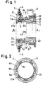
- a clutch release bearing device 1 comprises a first member 2, a second member 3, a sleeve member 4 and a detent member 5.
- the first member 2 includes an inner race 21 which is axially slidably mounted on an input shaft of a transmission (not shown in the FIGURES).
- the first member 2 further includes an outer race 22 which is formed in the cylindrical shaped configuration.
- the outer race 22 is connected with a clutch release fork 6 which is connected with a clutch release cylinder (not shown in the FIGURES).
- the outer race 22 can be rotatable relative to the inner race 21 through a plurality of balls 23 as rolling elements of the bearing mechanism which are disposed between the inner race and the outer race.
- a groove portion 21a for engaging with a detent member 5 (described later) is disposed on an outer circumference of the inner race 21.
- the second member 3 is formed in the cylindrical shaped configuration and mounted on the outer circumference of the inner race 21.
- a diaphragm spring 7 as a clutch spring of a clutch mechanism (not shown in the FIGURES) is supported on the outer circumference of the second member 3.
- the second member 3 has a first slot 3a for engaging with the sleeve member 4 (described later) and a second slot 3b for engaging with the detent member 5 (described later) .
- a projecting portion 3c for functioning as a fulcrum portion of an operation of a tool 10 (described later) is formed on a side portion of the second member 3.
- the sleeve member 4 is formed in the cylindrical shaped configuration and axially slidably disposed on the outer circumference of the inner race 21.
- the sleeve member 4 includes a first groove 4a and the inner race 21 has a groove 21b.
- the sleeve member 4 is slidably supported on an outer circumference of the Inner race 21 through a ring 8 which is disposed in the first groove 4a and the groove 21b so as not to detach the sleeve member 4 from the inner race 21.
- the sleeve member 4 can be inserted into the first slot 3a.
- the sleeve member 4 has a restrict portion 4b for contacting with the detent member 5 and a cut portion 4c into which the detent member 5 can expand.
- a second groove 4d for engaging with the tool 10 is disposed on an outer circumference of the sleeve member 4.
- the detent member 5 has mainly a circular shaped configuration 5a in section and is formed in the incomplete ring shaped configuration with a cut portion on the circumference.
- the detent member 5 includes a plurality of sectional semicircular portions 5b each of which is formed by cutting out the rest semicircular portion.
- the detent member 5 is supported in the second slot 3b so as to be expanded and further engaged with the groove portion 21a. Furthermore, the detent member 5 is contacted with the restrict portion 4b of the sleeve member 4.
- the second slot 3b comprises a plurality of through portions in the radial direction of the second member 3 so as to engage with the circular portions 5a.
- the second slot 3b further includes a plurality of unthrough portions for engaging with the semicircular portions 5b.
- a dish spring 9 is disposed between the inner race 21 and the sleeve member 4.
- the sleeve member 4 is always biassed by the dish spring 9 in a direction shown as an arrow B (indicates the direction which the first member 2 is engaged with the second member 3) in the FIG. 1 so as to contact the restrict portion 4b with the detent member 5.
- FIG. 1 a condition of the clutch release bearing device 1 which is assembled is shown.
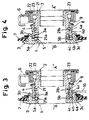
- the tool 10 is fit into the second groove 4d et the end thereof and the sleeve member 4 is slid in a direction shown as an arrow A (indicates the direction which the first member 2 is disengaged from the second member 3) against the elastic force of the dish spring 9 by rotating the tool 10 in the clockwise direction in FIG. 3 in such a manner that the projecting portion 3c acts as a fulcrum portion.
- the restrict portion 4b of the sleeve member 4 is disengaged from the detent member 5 and the detent member 5 is opposite to the cut portion 4c of the sleeve member 4.
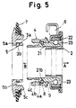
- the circular portions 5a are disengaged from the groove portion 21a and the detent member 5 is expanded into the cut portion 4c by the outer circumference of the inner race 21. Therefore the first member 2 is completely disengaged from the second member 3 shown in FIG. 5 by the further slide movement of the first member 2.
- the sleeve member 4 and the dish spring 9 are continued to be mounted on the first member 2 and the detent member 5 is supported on the second member 3.
- the first member 2 and the second member 3 which are shown in FIG. 5 are assembled, the first member 2 is slid in the arrow B direction so as to insert the inner race 21 into the inner circumference and fit the sleeve member 4 into the first slot 3a. Therefore the detent member 5 is expanded by the outer circumference of the inner race 21 and the circular portions 5a of the detent member 5 engage with the groove portion 21a. Consequently, the detent member 5 is opposite to the restrict portion 4b. Further the inner race 21 includes an inclination at the left thereof so as that the detent member 5 easily goes up the outer circumference of the inner race 21. Consequently, the inner race 21 of the first member 2 engages with the second member 3 through the detent member 5 as shown in FIG. 1.
- the clutch release bearing device 1 of the invention can be disassembled into the first member 2 and the second member 3, the clutch release bearing device 1 is convenient for the mounting operation of the transmission and the clutch mechanism. Further, when the first member 2 and the second member 3 are disengaged, the sleeve member 4 may be slid merely in the arrow A direction without slid in the arrow B direction. Moreover, since the sleeve member 4 is moved by the tool 10, the first member 2 and the second member 3 are completely disengaged. Furthermore, the sleeve member 4 does not need the precise size in relation to the detent member 5 and the sleeve member 4 and the detent member 5 are easily manufactured.
- the clutch release bearing device 1 when the clutch release bearing device 1 is assembled, the detent member 5 is retained with three points indicated as arrows P, Q and R shown in FIG. 1.
- Each of the arrows P, Q and R indicates respectively the radial force operated from the sleeve member 4, the axial force operated from the second member 3 and the oblique force to the axial direction operated from the first member 2. Therefore the clutch release bearing device 1 of the invention can decrease the stress which is generated between the detent member 5 and each of the sleeve member 4, the second member 3 and the first member 2. Consequently, the above elements do not have to have the strength.
- the clutch release bearing device 1 when the clutch release bearing device 1 is assembled, the clutch release bearing device 1 does not comprise a clearance between the first member 2 and the second member 3 in the axial direction (shown as the arrow A and the arrow B of the FIG.1). Therefore the first member 2 does not have to be pulled in the arrow A direction of the FIG. 1 by the clutch release fork 6.
- a clutch release bearing device includes a first member for connected with a clutch release fork and which includes a bearing mechanism, a second member slidably disposed on the first member and for which retains a clutch spring, a sleeve member which is mounted on the first member and a detent member which engages the first member and the second member, wherein the first member includes a groove portion, the sleeve member includes a restrict portion and the detent member is engaged with the groove portion and contacted with the restrict portion.
Landscapes
- Engineering & Computer Science (AREA)
- General Engineering & Computer Science (AREA)
- Mechanical Engineering (AREA)
- Mechanical Operated Clutches (AREA)
Applications Claiming Priority (2)
| Application Number | Priority Date | Filing Date | Title |
|---|---|---|---|
| JP31810792A JP3232720B2 (ja) | 1992-11-27 | 1992-11-27 | クラツチレリーズベアリング組立体 |
| JP318107/92 | 1992-11-27 |
Publications (3)
| Publication Number | Publication Date |
|---|---|
| EP0599328A2 true EP0599328A2 (fr) | 1994-06-01 |
| EP0599328A3 EP0599328A3 (fr) | 1994-10-12 |
| EP0599328B1 EP0599328B1 (fr) | 1997-07-30 |
Family
ID=18095574
Family Applications (1)
| Application Number | Title | Priority Date | Filing Date |
|---|---|---|---|
| EP93119052A Expired - Lifetime EP0599328B1 (fr) | 1992-11-27 | 1993-11-25 | Butée d'embrayage |
Country Status (4)
| Country | Link |
|---|---|
| US (1) | US5423405A (fr) |
| EP (1) | EP0599328B1 (fr) |
| JP (1) | JP3232720B2 (fr) |
| DE (1) | DE69312647T2 (fr) |
Cited By (2)
| Publication number | Priority date | Publication date | Assignee | Title |
|---|---|---|---|---|
| FR2751387A1 (fr) * | 1996-07-17 | 1998-01-23 | Exedy Corp | Mecanisme de retenue d'anneau en fil metallique et dispositif de debrayage pour un embrayage du type a traction |
| CN114135593A (zh) * | 2022-02-08 | 2022-03-04 | 深圳市悦成汽车技术有限公司 | 一种双离合器分离结构 |
Families Citing this family (9)
| Publication number | Priority date | Publication date | Assignee | Title |
|---|---|---|---|---|
| US5653322A (en) * | 1996-01-30 | 1997-08-05 | Borg-Warner Automotive, Inc. | Two piece clutch assembly having twist lock joint |
| US5653323A (en) * | 1996-02-21 | 1997-08-05 | L & S Bearing Co. | Clutch release bearing assembly |
| US6179470B1 (en) * | 1998-08-19 | 2001-01-30 | Hoffco/Comet Industries, Inc. | Self-lubricating bearing |
| US6371266B1 (en) | 2000-04-28 | 2002-04-16 | Eaton Corporation | Modular pull-type release system |
| US6634866B2 (en) | 2001-08-17 | 2003-10-21 | Borgwarner, Inc. | Method and apparatus for providing a hydraulic transmission pump assembly having a one way clutch |
| US6588559B2 (en) | 2001-09-18 | 2003-07-08 | Borgwarner, Inc. | Two-way clutch biasing assembly |
| US6554113B2 (en) | 2001-09-20 | 2003-04-29 | Borgwarner, Inc. | Torque limiting accessory drive assembly |
| WO2015120129A1 (fr) * | 2014-02-05 | 2015-08-13 | Eaton Corporation | Cartouche de palier sollicitée par ressort de compresseur à suralimentation |
| DE102017221153A1 (de) * | 2017-11-27 | 2019-05-29 | Ford Global Technologies, Llc | Lageranordnung und Lenkgetriebe |
Family Cites Families (17)
| Publication number | Priority date | Publication date | Assignee | Title |
|---|---|---|---|---|
| DE2944648A1 (de) * | 1979-11-06 | 1981-05-14 | Skf Kugellagerfabriken Gmbh, 8720 Schweinfurt | Vorrichtung zum befestigen einer achse o.dgl. in einer nabe und anwendung derselben |
| DE3150150A1 (de) * | 1981-12-18 | 1983-06-30 | Fichtel & Sachs Ag, 8720 Schweinfurt | Ausruecksystem fuer eine gezogene reibungskupplung mit verriegelungseinrichtung |
| GB2131515B (en) * | 1982-11-19 | 1986-09-03 | Automotive Products Plc | A friction clutch for a vehicle |
| FR2557234B1 (fr) * | 1983-12-27 | 1989-03-31 | Valeo | Montage de butee de debrayage, et butee de debrayage propre a un tel montage |
| JPS60245837A (ja) * | 1984-05-07 | 1985-12-05 | オートモーチブ プロダクツ ピーエルシー | 摩擦クラツチ・レリーズ機構 |
| FR2576649B1 (fr) * | 1985-01-28 | 1987-04-30 | Skf Cie Applic Mecanique | Dispositif de butee d'embrayage tiree et procede de mise en place associe |
| GB8514600D0 (en) * | 1985-06-10 | 1985-07-10 | Automotive Prod Plc | Friction clutch |
| FR2588051B1 (fr) * | 1985-06-28 | 1987-12-18 | Valeo | Montage de butee de debrayage, notamment pour vehicule automobile |
| FR2588336B1 (fr) * | 1985-10-09 | 1990-01-26 | Fraymon Sa | Montage de butee de debrayage notamment pour vehicules automobiles |
| GB2195413B (en) * | 1986-09-24 | 1990-10-17 | Automotive Products Plc | A friction clutch for a vehicle |
| DE3632884C2 (de) * | 1986-09-27 | 1995-04-27 | Fichtel & Sachs Ag | Gezogene Membranfederkupplung mit Schnappverbindung |
| US4947975A (en) * | 1987-06-04 | 1990-08-14 | Kabushiki Kaisha Daikin Seisakusho | Release bearing mechanism of a clutch |
| FR2629884B1 (fr) * | 1988-04-08 | 1991-03-08 | Valeo | Butee de debrayage notamment pour vehicule automobile |
| JP2574928B2 (ja) * | 1990-05-24 | 1997-01-22 | 株式会社エクセディ | プルタイプクラッチのレリーズ機構 |
| JPH04105638U (ja) * | 1991-02-21 | 1992-09-11 | 株式会社大金製作所 | プルタイプクラツチ用レリーズ装置 |
| KR930004649A (ko) * | 1991-08-17 | 1993-03-22 | 원본미기재 | 당김형태 마찰 클러치의 부정합체계 |
| JPH06237522A (ja) * | 1993-02-08 | 1994-08-23 | Mitsubishi Electric Corp | 直列コンデンサ保護装置 |
-
1992
- 1992-11-27 JP JP31810792A patent/JP3232720B2/ja not_active Expired - Fee Related
-
1993
- 1993-11-25 DE DE69312647T patent/DE69312647T2/de not_active Expired - Fee Related
- 1993-11-25 EP EP93119052A patent/EP0599328B1/fr not_active Expired - Lifetime
- 1993-11-26 US US08/157,293 patent/US5423405A/en not_active Expired - Lifetime
Cited By (3)
| Publication number | Priority date | Publication date | Assignee | Title |
|---|---|---|---|---|
| FR2751387A1 (fr) * | 1996-07-17 | 1998-01-23 | Exedy Corp | Mecanisme de retenue d'anneau en fil metallique et dispositif de debrayage pour un embrayage du type a traction |
| CN114135593A (zh) * | 2022-02-08 | 2022-03-04 | 深圳市悦成汽车技术有限公司 | 一种双离合器分离结构 |
| CN114135593B (zh) * | 2022-02-08 | 2022-05-10 | 深圳市悦成汽车技术有限公司 | 一种双离合器分离结构 |
Also Published As
| Publication number | Publication date |
|---|---|
| JP3232720B2 (ja) | 2001-11-26 |
| DE69312647D1 (de) | 1997-09-04 |
| EP0599328A3 (fr) | 1994-10-12 |
| US5423405A (en) | 1995-06-13 |
| DE69312647T2 (de) | 1998-01-29 |
| JPH06159390A (ja) | 1994-06-07 |
| EP0599328B1 (fr) | 1997-07-30 |
Similar Documents
| Publication | Publication Date | Title |
|---|---|---|
| SU1577707A3 (ru) | Фрикционное сцепление дл транспортного средства | |
| US4399898A (en) | Device for releasably securing a shaft in a hub | |
| EP0599328B1 (fr) | Butée d'embrayage | |
| US5318162A (en) | Release apparatus for pull-type friction clutches | |
| EP0044691B1 (fr) | Dispositif de débrayage par traction | |
| US4109773A (en) | Release bearing assemblies for vehicle clutches | |
| KR920000378B1 (ko) | 클러치의 릴리즈 베아링 기구 | |
| EP0150815A1 (fr) | Dispositif de débrayage | |
| US5014840A (en) | Release bearing mechanism of a clutch | |
| US5979626A (en) | One-way clutch | |
| JPS63145827A (ja) | クラツチのレリ−ズベアリング機構 | |
| US5979629A (en) | Clutch pressing assembly | |
| EP0167287A1 (fr) | Embrayage à friction | |
| US4344517A (en) | Clutch release device | |
| US5758757A (en) | Wire ring retaining collar and release device for a pull type clutch mechanism | |
| US6371266B1 (en) | Modular pull-type release system | |
| ES8404477A1 (es) | Tope de desembrague autocentrable. | |
| GB2211264A (en) | A clutch release mechanism | |
| JP2002364671A (ja) | クラッチレリーズ軸受用調心ばね | |
| JPH09151962A (ja) | プルタイプクラッチ用レリーズ装置 | |
| JPH0728420Y2 (ja) | クラッチのレリーズベアリング機構 | |
| JP2729311B2 (ja) | クラッチレリーズ用軸受ユニット | |
| JPH10176724A (ja) | クラッチレリーズ軸受装置 | |
| US5240097A (en) | Pull-type clutch | |
| JPH077628Y2 (ja) | スナップリング支持カラー |
Legal Events
| Date | Code | Title | Description |
|---|---|---|---|
| PUAI | Public reference made under article 153(3) epc to a published international application that has entered the european phase |
Free format text: ORIGINAL CODE: 0009012 |
|
| AK | Designated contracting states |
Kind code of ref document: A2 Designated state(s): DE FR |
|
| PUAL | Search report despatched |
Free format text: ORIGINAL CODE: 0009013 |
|
| AK | Designated contracting states |
Kind code of ref document: A3 Designated state(s): DE FR |
|
| 17P | Request for examination filed |
Effective date: 19940928 |
|
| 17Q | First examination report despatched |
Effective date: 19950720 |
|
| GRAG | Despatch of communication of intention to grant |
Free format text: ORIGINAL CODE: EPIDOS AGRA |
|
| GRAH | Despatch of communication of intention to grant a patent |
Free format text: ORIGINAL CODE: EPIDOS IGRA |
|
| GRAH | Despatch of communication of intention to grant a patent |
Free format text: ORIGINAL CODE: EPIDOS IGRA |
|
| GRAA | (expected) grant |
Free format text: ORIGINAL CODE: 0009210 |
|
| AK | Designated contracting states |
Kind code of ref document: B1 Designated state(s): DE FR |
|
| REF | Corresponds to: |
Ref document number: 69312647 Country of ref document: DE Date of ref document: 19970904 |
|
| ET | Fr: translation filed | ||
| PLBE | No opposition filed within time limit |
Free format text: ORIGINAL CODE: 0009261 |
|
| STAA | Information on the status of an ep patent application or granted ep patent |
Free format text: STATUS: NO OPPOSITION FILED WITHIN TIME LIMIT |
|
| 26N | No opposition filed | ||
| PGFP | Annual fee paid to national office [announced via postgrant information from national office to epo] |
Ref country code: FR Payment date: 19981110 Year of fee payment: 6 |
|
| PGFP | Annual fee paid to national office [announced via postgrant information from national office to epo] |
Ref country code: DE Payment date: 19981207 Year of fee payment: 6 |
|
| PG25 | Lapsed in a contracting state [announced via postgrant information from national office to epo] |
Ref country code: FR Free format text: LAPSE BECAUSE OF NON-PAYMENT OF DUE FEES Effective date: 20000731 |
|
| PG25 | Lapsed in a contracting state [announced via postgrant information from national office to epo] |
Ref country code: DE Free format text: LAPSE BECAUSE OF NON-PAYMENT OF DUE FEES Effective date: 20000901 |
|
| REG | Reference to a national code |
Ref country code: FR Ref legal event code: ST |