EP0599331A1 - Ascenceur propulsé par un moteur linéaire - Google Patents
Ascenceur propulsé par un moteur linéaire Download PDFInfo
- Publication number
- EP0599331A1 EP0599331A1 EP93119059A EP93119059A EP0599331A1 EP 0599331 A1 EP0599331 A1 EP 0599331A1 EP 93119059 A EP93119059 A EP 93119059A EP 93119059 A EP93119059 A EP 93119059A EP 0599331 A1 EP0599331 A1 EP 0599331A1
- Authority
- EP
- European Patent Office
- Prior art keywords
- elevator
- primary
- motor
- counterweight
- shaft
- Prior art date
- Legal status (The legal status is an assumption and is not a legal conclusion. Google has not performed a legal analysis and makes no representation as to the accuracy of the status listed.)
- Granted
Links
- 238000004804 winding Methods 0.000 claims abstract description 28
- 230000006698 induction Effects 0.000 claims abstract description 5
- 239000004020 conductor Substances 0.000 claims abstract 4
- 229920001971 elastomer Polymers 0.000 claims description 2
- 239000011810 insulating material Substances 0.000 claims 1
- XEEYBQQBJWHFJM-UHFFFAOYSA-N Iron Chemical compound [Fe] XEEYBQQBJWHFJM-UHFFFAOYSA-N 0.000 description 4
- 229910000831 Steel Inorganic materials 0.000 description 3
- 239000004411 aluminium Substances 0.000 description 3
- XAGFODPZIPBFFR-UHFFFAOYSA-N aluminium Chemical compound [Al] XAGFODPZIPBFFR-UHFFFAOYSA-N 0.000 description 3
- 229910052782 aluminium Inorganic materials 0.000 description 3
- 238000010276 construction Methods 0.000 description 3
- 239000010959 steel Substances 0.000 description 3
- 239000004744 fabric Substances 0.000 description 2
- 239000000463 material Substances 0.000 description 2
- RYGMFSIKBFXOCR-UHFFFAOYSA-N Copper Chemical compound [Cu] RYGMFSIKBFXOCR-UHFFFAOYSA-N 0.000 description 1
- 238000012512 characterization method Methods 0.000 description 1
- 239000010949 copper Substances 0.000 description 1
- 229910052802 copper Inorganic materials 0.000 description 1
- 238000010586 diagram Methods 0.000 description 1
- 239000003365 glass fiber Substances 0.000 description 1
- 238000009434 installation Methods 0.000 description 1
- 229910052742 iron Inorganic materials 0.000 description 1
- 238000004519 manufacturing process Methods 0.000 description 1
- 238000005096 rolling process Methods 0.000 description 1
- 229920006395 saturated elastomer Polymers 0.000 description 1
Images

Classifications
-
- H—ELECTRICITY
- H02—GENERATION; CONVERSION OR DISTRIBUTION OF ELECTRIC POWER
- H02K—DYNAMO-ELECTRIC MACHINES
- H02K41/00—Propulsion systems in which a rigid body is moved along a path due to dynamo-electric interaction between the body and a magnetic field travelling along the path
- H02K41/02—Linear motors; Sectional motors
- H02K41/025—Asynchronous motors
-
- B—PERFORMING OPERATIONS; TRANSPORTING
- B66—HOISTING; LIFTING; HAULING
- B66B—ELEVATORS; ESCALATORS OR MOVING WALKWAYS
- B66B11/00—Main component parts of lifts in, or associated with, buildings or other structures
- B66B11/04—Driving gear ; Details thereof, e.g. seals
- B66B11/0407—Driving gear ; Details thereof, e.g. seals actuated by an electrical linear motor
Definitions
- the present invention relates to a linear motor according to the introductory part of claim 1 and to an elevator according to the introductory part of claim 6.
- the operating power of an elevator is generally obtained from a rotating electromotor, used to drive an elevator car suspended on a hoisting rope.
- the hoisting rope passes via a traction sheave rotated by the electromotor and possibly via deflecting pulleys, a counterweight being suspended at the other end of the hoisting rope.
- the electromotor is coupled either directly or via a gear to the shaft of the traction sheave.
- the elevator machine i.e. the electromotor, gear and possibly the operating system of the electromotor, as well as the elevator control unit are placed in a separate space, a machine room, which is normally built on top of the elevator shaft.
- a problem with equipment using a linear motor is the mounting and supporting of the long secondary component.
- the secondary circuit is normally composed of several successive elements joined together and suitably attached to supporting structures.
- the secondary part may have a length of several tens of metres, which makes it difficult to assemble and install the secondary part on site in the elevator shaft.
- the linear motor should not occupy too much of the cross-sectional area of the elevator shaft, because otherwise the space saved through the omission of a machine room would be wasted in the elevator shaft. In a tall building, even a slight increase in the cross-sectional area of the shaft may take up more floor area than a machine room.
- the object of the invention is to create a new linear motor which is easy to install and assemble even in the case of long motors and which can be reliably attached to supporting structures without complex supporting elements.
- a further object of the invention is to produce a new elevator operated by a linear motor whose secondary circuit is easy to install in the shaft and occupies only a minimal portion of its cross-sectional area. To achieve this, the invention is characterized by the features presented in the characterization parts of claims 1 and 6.
- the solution of the invention permits easy production of long secondary components for linear motors.
- the flexible band-like secondary circuit can be manufactured as a full-length component in the factory and rolled up for transport. Installation of the secondary component in the elevator shaft is easy as there is no need to join successive parts together but the band is only attached by its ends to supporting structures.
- the flat structure of the band does not take up any extra space in the depthwise direction of the shaft, and the motor can be accommodated within the counterweight.
- the secondary component of the linear motor is fitted between the two halves of a split stator, the secondary component is light as it is possible to use a construction without an iron circuit.
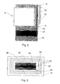
- the elevator car As shown in fig. 1, the elevator car 1, supported by hoisting ropes 2, travels in an elevator shaft.
- the hoisting ropes 2 are attached to the overhead beam 3 of the car frame supporting the elevator car.
- the hoisting ropes pass over a deflecting pulley 4 mounted in the upper part of the elevator shaft, the other end of the ropes being attached to a counterweight 5.
- the elevator shaft is provided with guide rails 6 and 7 for the elevator car 1 and the counterweight 5.
- the guides of the car and counterweight lean against the guide rails, preventing their lateral motion.
- the primary winding 8 of the linear motor Fitted in the counterweight is the primary winding 8 of the linear motor.
- the primary winding is manufactured as a double structure, so that the motor has separate windings on the side facing the shaft wall and on the side facing the elevator car. Between the two halves of the primary winding there is an air gap extending vertically through the counterweight, the band-like secondary winding being so fitted that it runs through this air gap.
- the band 9 forming the secondary winding of the motor is attached with elastic fixing elements 10 to the top and bottom of the shaft, so that the secondary component always remains tensioned to a suitable tightness. In this case the secondary component is so mounted that it runs centrally through the counterweight, the hoisting ropes being placed on either side of it.
- Other alternatives regarding the placement of the secondary winding are also possible within the framework of the invention.
- the counterweight 5 is provided with magnetic brakes 13. Via a cable 12 attached to the counterweight, the primary winding of the motor is linked with an elevator control unit interface 15 provided in the shaft wall. The elevator car is likewise connected to the interface 15 via a trailing cable 14. The power required by the primary side of the linear motor is supplied via cable 12 and the motor is controlled by a motor drive system placed in the elevator control unit.
- the linear motor is an induction motor, in which the primary winding induces a short-circuit current in the secondary windings. The speed of the motor is adjusted by varying the supply frequency and/or voltage of the frequency converter or inverter feeding the motor.
- Fig. 2 illustrates the structural principle of the linear motor of the invention.
- the stator which in the elevator application presented in fig. 1 is placed in the counter-weight, consists of two parallel plate-shaped halves 21 and 22 placed at a distance from each other.
- the frame of the primary winding is composed of sheets to form the magnetic circuit of the motor, and it is provided with grooves 23 oriented in a direction perpendicular to the travel direction of the motor, the primary windings being placed in these grooves.
- the secondary component 9 of the motor Between the two halves of the primary side is the secondary component 9 of the motor, a band-shaped element extending in its lengthwise direction outside the primary part.
- the width of the band 9 is substantially of the same order with that of the stator core packet of stampings
- the band consists of a mesh or fabric 24 forming a supporting structure, made e.g. of glass fibre or steel wire. Attached to either side of the supporting structure is a conducting plexus 25 made of aluminium or copper, forming the secondary winding of the motor.
- the secondary winding can also be made from conducting rods connected together at their ends to form a short-circuit winding.
- the primary and secondary parts are separated by an air gap.
- the structure formed by the supporting structure and the winding is flexible in the lengthwise direction, whereas in its widthwise direction it is substantially straight and inflexible.
- Fig. 3 presents a diagram representing another embodiment of the invention.
- the primary part of the motor consists of an annular iron core 31 in which the primary winding 32 is so fitted that it encircles the opening 33 formed inside the core.
- the winding is annular, so no end connections are needed.
- Fitted inside the primary part is a band-shaped secondary part 34 which consists of several layers and is movable relative to the primary part, an air gap 38 being provided between the primary and secondary parts.
- the secondary winding of the linear motor consists of conducting aluminium bars 35 forming the outer layers of the secondary part, facing the primary winding. The bars are connected together at their ends to form a short-circuit winding.
- steel bars 36 On either side of the band-shaped secondary part, under the aluminium bars, are steel bars 36 forming the iron part of the magnetic circuit of the secondary component of the motor. Between the steel bars, in the middle of the secondary band, is a mesh or fabric 37 which constitutes the supporting structure of the band and is saturated e.g. with rubber to isolate the magnetic circuits of the two halves of the secndary part from each other.
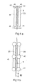
- Fig. 4 illustrates an arrangement designed to maintain a constant air gap between the primary and secondary parts of the linear motor in the motor structure presented in fig. 2.
- the motor is depicted in top view and in fig. 4b) in lateral view, as seen from the direction of the plane of the secondary part.
- Attached to the two halves 22 and 23 of the primary part are roller guides 41 and 42 which rotate on their axles, rolling along the level surfaces 43 and 44 of the secondary part.
- the secondary band has been made somewhat wider than the secondary winding itself, the edges being made of a material resistant to the wear caused by the roller guides. Alternatively, the edges of the band are coated with wear-resistant material in the areas receiving the pressure of the roller guides.
- a corresponding guide structure is also used in connection with the embodiment in fig. 3 to maintain a constant air gap between the primary and secondary parts.
- the motor is only provided with roller guides placed at the ends of the primary part of the motor.
Landscapes
- Engineering & Computer Science (AREA)
- Civil Engineering (AREA)
- Mechanical Engineering (AREA)
- Structural Engineering (AREA)
- Physics & Mathematics (AREA)
- Chemical & Material Sciences (AREA)
- Combustion & Propulsion (AREA)
- Electromagnetism (AREA)
- Power Engineering (AREA)
- Types And Forms Of Lifts (AREA)
- Linear Motors (AREA)
- Cage And Drive Apparatuses For Elevators (AREA)
Applications Claiming Priority (2)
| Application Number | Priority Date | Filing Date | Title |
|---|---|---|---|
| FI925337 | 1992-11-25 | ||
| FI925337A FI98256C (fi) | 1992-11-25 | 1992-11-25 | Lineaari-induktiomoottori ja lineaarimoottorilla toimiva hissi |
Publications (2)
| Publication Number | Publication Date |
|---|---|
| EP0599331A1 true EP0599331A1 (fr) | 1994-06-01 |
| EP0599331B1 EP0599331B1 (fr) | 1997-03-12 |
Family
ID=8536271
Family Applications (1)
| Application Number | Title | Priority Date | Filing Date |
|---|---|---|---|
| EP93119059A Expired - Lifetime EP0599331B1 (fr) | 1992-11-25 | 1993-11-25 | Ascenceur propulsé par un moteur linéaire |
Country Status (4)
| Country | Link |
|---|---|
| EP (1) | EP0599331B1 (fr) |
| DE (1) | DE69308752T2 (fr) |
| ES (1) | ES2101199T3 (fr) |
| FI (1) | FI98256C (fr) |
Cited By (8)
| Publication number | Priority date | Publication date | Assignee | Title |
|---|---|---|---|---|
| EP0755110A1 (fr) * | 1995-07-20 | 1997-01-22 | Satomi Arimoto | Méthode et procédé de propulsion par induction magnétique |
| EP0785162A1 (fr) | 1996-01-19 | 1997-07-23 | Inventio Ag | Système d'entraînement pour ascenseur |
| US5696417A (en) * | 1994-07-01 | 1997-12-09 | Arimoto; Satomi | Electromagnetic induction driving method and device |
| CN1067496C (zh) * | 1995-12-29 | 2001-06-20 | 福井孝夫 | 电磁感应驱动方法和装置 |
| DE10137192A1 (de) * | 2001-07-31 | 2003-02-27 | Joerg Bobzin | Asynchronmaschine |
| CN1319840C (zh) * | 2004-03-01 | 2007-06-06 | 株式会社日立制作所 | 电梯装置 |
| SG134994A1 (en) * | 2002-10-29 | 2007-09-28 | Inventio Ag | Lift counterweight |
| WO2014189492A1 (fr) * | 2013-05-21 | 2014-11-27 | Otis Elevator Company | Alimentation sans fil pour ascenseur autopropulsé |
Citations (5)
| Publication number | Priority date | Publication date | Assignee | Title |
|---|---|---|---|---|
| FR2278193A1 (fr) * | 1974-07-12 | 1976-02-06 | Sulzer Constr Mecan | Coupleur electromagnetique lineaire |
| US3954037A (en) * | 1975-07-09 | 1976-05-04 | Emilio Retana Rodriguez | Linear motor band saw |
| US4402386A (en) * | 1980-09-30 | 1983-09-06 | Otis Elevator Company | Self-powered elevator using a linear electric motor as counterweight |
| US4803387A (en) * | 1987-06-29 | 1989-02-07 | Fmc Corporation | Electric drive motor |
| US5062501A (en) * | 1989-03-03 | 1991-11-05 | Otis Elevator Company | Elevator with linear motor counterweight assembly |
-
1992
- 1992-11-25 FI FI925337A patent/FI98256C/fi not_active IP Right Cessation
-
1993
- 1993-11-25 DE DE69308752T patent/DE69308752T2/de not_active Expired - Fee Related
- 1993-11-25 EP EP93119059A patent/EP0599331B1/fr not_active Expired - Lifetime
- 1993-11-25 ES ES93119059T patent/ES2101199T3/es not_active Expired - Lifetime
Patent Citations (5)
| Publication number | Priority date | Publication date | Assignee | Title |
|---|---|---|---|---|
| FR2278193A1 (fr) * | 1974-07-12 | 1976-02-06 | Sulzer Constr Mecan | Coupleur electromagnetique lineaire |
| US3954037A (en) * | 1975-07-09 | 1976-05-04 | Emilio Retana Rodriguez | Linear motor band saw |
| US4402386A (en) * | 1980-09-30 | 1983-09-06 | Otis Elevator Company | Self-powered elevator using a linear electric motor as counterweight |
| US4803387A (en) * | 1987-06-29 | 1989-02-07 | Fmc Corporation | Electric drive motor |
| US5062501A (en) * | 1989-03-03 | 1991-11-05 | Otis Elevator Company | Elevator with linear motor counterweight assembly |
Cited By (10)
| Publication number | Priority date | Publication date | Assignee | Title |
|---|---|---|---|---|
| US5696417A (en) * | 1994-07-01 | 1997-12-09 | Arimoto; Satomi | Electromagnetic induction driving method and device |
| EP0755110A1 (fr) * | 1995-07-20 | 1997-01-22 | Satomi Arimoto | Méthode et procédé de propulsion par induction magnétique |
| CN1067496C (zh) * | 1995-12-29 | 2001-06-20 | 福井孝夫 | 电磁感应驱动方法和装置 |
| EP0785162A1 (fr) | 1996-01-19 | 1997-07-23 | Inventio Ag | Système d'entraînement pour ascenseur |
| US5751076A (en) * | 1996-01-19 | 1998-05-12 | Inventio Ag | Drive system for lifts |
| DE10137192A1 (de) * | 2001-07-31 | 2003-02-27 | Joerg Bobzin | Asynchronmaschine |
| SG134994A1 (en) * | 2002-10-29 | 2007-09-28 | Inventio Ag | Lift counterweight |
| CN1319840C (zh) * | 2004-03-01 | 2007-06-06 | 株式会社日立制作所 | 电梯装置 |
| WO2014189492A1 (fr) * | 2013-05-21 | 2014-11-27 | Otis Elevator Company | Alimentation sans fil pour ascenseur autopropulsé |
| US10196240B2 (en) | 2013-05-21 | 2019-02-05 | Otis Elevator Company | Wireless power supply for self-propelled elevator |
Also Published As
| Publication number | Publication date |
|---|---|
| DE69308752D1 (de) | 1997-04-17 |
| FI98256B (fi) | 1997-01-31 |
| FI98256C (fi) | 1997-05-12 |
| EP0599331B1 (fr) | 1997-03-12 |
| DE69308752T2 (de) | 1997-07-03 |
| FI925337A0 (fi) | 1992-11-25 |
| ES2101199T3 (es) | 1997-07-01 |
| FI925337L (fi) | 1994-05-26 |
Similar Documents
| Publication | Publication Date | Title |
|---|---|---|
| US5751076A (en) | Drive system for lifts | |
| JP6979883B2 (ja) | 電気リニアモータ | |
| CN1120799C (zh) | 电梯 | |
| US4570753A (en) | Elevator hoisting device | |
| US5566784A (en) | Self-propelled elevator system | |
| KR960015738B1 (ko) | 리니어모터 구동방식 엘리베이터장치 | |
| US9815665B2 (en) | Battery mounting in elevator hoistway | |
| EP0503980B1 (fr) | Ascenseur entraîné par un moteur linéaire plat | |
| EP0599331B1 (fr) | Ascenceur propulsé par un moteur linéaire | |
| US5090516A (en) | Elevator linear motor bus bar | |
| CN111655604B (zh) | 线性电动机 | |
| US5736693A (en) | Elevator door drive using dual secondary linear induction motor | |
| GB2281664A (en) | Linear motor and elevator and conveyer using same | |
| JP2007076787A (ja) | エレベータの非接触給電装置 | |
| JP2907722B2 (ja) | リニアモータ駆動エレベータおよびその案内レール | |
| CN116036618A (zh) | 高速弧线轨道飞行威亚设备 | |
| WO2002027901A1 (fr) | Moteur lineaire pour ascenseur | |
| CN1833981B (zh) | 电梯装置 | |
| KR0137949Y1 (ko) | 선형 구동 방식 엘리베이터장치 | |
| KR20210056032A (ko) | 엘리베이터용 리니어 모터 | |
| EP4580979A1 (fr) | Terminal de câble, ascenseur et procédé d'installation de câble de suspension d'ascenseur | |
| HK40032674A (en) | Electric linear motor | |
| KR970009387B1 (ko) | 리니어 모터를 이용한 엘리베이터의 브레이크 장치 | |
| JPH0767314A (ja) | リニアモーター | |
| HK1251214B (zh) | 线性电机 |
Legal Events
| Date | Code | Title | Description |
|---|---|---|---|
| PUAI | Public reference made under article 153(3) epc to a published international application that has entered the european phase |
Free format text: ORIGINAL CODE: 0009012 |
|
| AK | Designated contracting states |
Kind code of ref document: A1 Designated state(s): DE ES FR IT SE |
|
| 17P | Request for examination filed |
Effective date: 19941125 |
|
| 17Q | First examination report despatched |
Effective date: 19950412 |
|
| GRAG | Despatch of communication of intention to grant |
Free format text: ORIGINAL CODE: EPIDOS AGRA |
|
| GRAH | Despatch of communication of intention to grant a patent |
Free format text: ORIGINAL CODE: EPIDOS IGRA |
|
| GRAH | Despatch of communication of intention to grant a patent |
Free format text: ORIGINAL CODE: EPIDOS IGRA |
|
| GRAA | (expected) grant |
Free format text: ORIGINAL CODE: 0009210 |
|
| AK | Designated contracting states |
Kind code of ref document: B1 Designated state(s): DE ES FR IT SE |
|
| REF | Corresponds to: |
Ref document number: 69308752 Country of ref document: DE Date of ref document: 19970417 |
|
| ITF | It: translation for a ep patent filed | ||
| ET | Fr: translation filed | ||
| PG25 | Lapsed in a contracting state [announced via postgrant information from national office to epo] |
Ref country code: SE Effective date: 19970612 |
|
| REG | Reference to a national code |
Ref country code: ES Ref legal event code: FG2A Ref document number: 2101199 Country of ref document: ES Kind code of ref document: T3 |
|
| PLBE | No opposition filed within time limit |
Free format text: ORIGINAL CODE: 0009261 |
|
| STAA | Information on the status of an ep patent application or granted ep patent |
Free format text: STATUS: NO OPPOSITION FILED WITHIN TIME LIMIT |
|
| 26N | No opposition filed | ||
| PGFP | Annual fee paid to national office [announced via postgrant information from national office to epo] |
Ref country code: FR Payment date: 20041010 Year of fee payment: 12 |
|
| PGFP | Annual fee paid to national office [announced via postgrant information from national office to epo] |
Ref country code: DE Payment date: 20041020 Year of fee payment: 12 |
|
| PGFP | Annual fee paid to national office [announced via postgrant information from national office to epo] |
Ref country code: ES Payment date: 20041104 Year of fee payment: 12 |
|
| PG25 | Lapsed in a contracting state [announced via postgrant information from national office to epo] |
Ref country code: IT Free format text: LAPSE BECAUSE OF NON-PAYMENT OF DUE FEES;WARNING: LAPSES OF ITALIAN PATENTS WITH EFFECTIVE DATE BEFORE 2007 MAY HAVE OCCURRED AT ANY TIME BEFORE 2007. THE CORRECT EFFECTIVE DATE MAY BE DIFFERENT FROM THE ONE RECORDED. Effective date: 20051125 |
|
| PG25 | Lapsed in a contracting state [announced via postgrant information from national office to epo] |
Ref country code: ES Free format text: LAPSE BECAUSE OF NON-PAYMENT OF DUE FEES Effective date: 20051126 |
|
| PG25 | Lapsed in a contracting state [announced via postgrant information from national office to epo] |
Ref country code: DE Free format text: LAPSE BECAUSE OF NON-PAYMENT OF DUE FEES Effective date: 20060601 |
|
| PG25 | Lapsed in a contracting state [announced via postgrant information from national office to epo] |
Ref country code: FR Free format text: LAPSE BECAUSE OF NON-PAYMENT OF DUE FEES Effective date: 20060731 |
|
| REG | Reference to a national code |
Ref country code: FR Ref legal event code: ST Effective date: 20060731 |
|
| REG | Reference to a national code |
Ref country code: ES Ref legal event code: FD2A Effective date: 20051126 |