EP0599332B1 - Connecteur actionnée par levier - Google Patents
Connecteur actionnée par levier Download PDFInfo
- Publication number
- EP0599332B1 EP0599332B1 EP93119060A EP93119060A EP0599332B1 EP 0599332 B1 EP0599332 B1 EP 0599332B1 EP 93119060 A EP93119060 A EP 93119060A EP 93119060 A EP93119060 A EP 93119060A EP 0599332 B1 EP0599332 B1 EP 0599332B1
- Authority
- EP
- European Patent Office
- Prior art keywords
- lever
- connector housing
- retaining pawl
- connector
- open position
- Prior art date
- Legal status (The legal status is an assumption and is not a legal conclusion. Google has not performed a legal analysis and makes no representation as to the accuracy of the status listed.)
- Expired - Lifetime
Links
- 230000000717 retained effect Effects 0.000 claims description 24
- 238000010276 construction Methods 0.000 description 7
- 230000004048 modification Effects 0.000 description 1
- 238000012986 modification Methods 0.000 description 1
- 230000001105 regulatory effect Effects 0.000 description 1
- 230000003014 reinforcing effect Effects 0.000 description 1
Images



Classifications
-
- H—ELECTRICITY
- H01—ELECTRIC ELEMENTS
- H01R—ELECTRICALLY-CONDUCTIVE CONNECTIONS; STRUCTURAL ASSOCIATIONS OF A PLURALITY OF MUTUALLY-INSULATED ELECTRICAL CONNECTING ELEMENTS; COUPLING DEVICES; CURRENT COLLECTORS
- H01R13/00—Details of coupling devices of the kinds covered by groups H01R12/70 or H01R24/00 - H01R33/00
- H01R13/62—Means for facilitating engagement or disengagement of coupling parts or for holding them in engagement
- H01R13/629—Additional means for facilitating engagement or disengagement of coupling parts, e.g. aligning or guiding means, levers, gas pressure electrical locking indicators, manufacturing tolerances
- H01R13/62933—Comprising exclusively pivoting lever
- H01R13/62955—Pivoting lever comprising supplementary/additional locking means
-
- H—ELECTRICITY
- H01—ELECTRIC ELEMENTS
- H01R—ELECTRICALLY-CONDUCTIVE CONNECTIONS; STRUCTURAL ASSOCIATIONS OF A PLURALITY OF MUTUALLY-INSULATED ELECTRICAL CONNECTING ELEMENTS; COUPLING DEVICES; CURRENT COLLECTORS
- H01R13/00—Details of coupling devices of the kinds covered by groups H01R12/70 or H01R24/00 - H01R33/00
- H01R13/62—Means for facilitating engagement or disengagement of coupling parts or for holding them in engagement
- H01R13/629—Additional means for facilitating engagement or disengagement of coupling parts, e.g. aligning or guiding means, levers, gas pressure electrical locking indicators, manufacturing tolerances
- H01R13/62933—Comprising exclusively pivoting lever
-
- H—ELECTRICITY
- H01—ELECTRIC ELEMENTS
- H01R—ELECTRICALLY-CONDUCTIVE CONNECTIONS; STRUCTURAL ASSOCIATIONS OF A PLURALITY OF MUTUALLY-INSULATED ELECTRICAL CONNECTING ELEMENTS; COUPLING DEVICES; CURRENT COLLECTORS
- H01R13/00—Details of coupling devices of the kinds covered by groups H01R12/70 or H01R24/00 - H01R33/00
- H01R13/62—Means for facilitating engagement or disengagement of coupling parts or for holding them in engagement
- H01R13/629—Additional means for facilitating engagement or disengagement of coupling parts, e.g. aligning or guiding means, levers, gas pressure electrical locking indicators, manufacturing tolerances
- H01R13/62905—Additional means for facilitating engagement or disengagement of coupling parts, e.g. aligning or guiding means, levers, gas pressure electrical locking indicators, manufacturing tolerances comprising a camming member
-
- H—ELECTRICITY
- H01—ELECTRIC ELEMENTS
- H01R—ELECTRICALLY-CONDUCTIVE CONNECTIONS; STRUCTURAL ASSOCIATIONS OF A PLURALITY OF MUTUALLY-INSULATED ELECTRICAL CONNECTING ELEMENTS; COUPLING DEVICES; CURRENT COLLECTORS
- H01R13/00—Details of coupling devices of the kinds covered by groups H01R12/70 or H01R24/00 - H01R33/00
- H01R13/62—Means for facilitating engagement or disengagement of coupling parts or for holding them in engagement
- H01R13/629—Additional means for facilitating engagement or disengagement of coupling parts, e.g. aligning or guiding means, levers, gas pressure electrical locking indicators, manufacturing tolerances
- H01R13/62933—Comprising exclusively pivoting lever
- H01R13/62938—Pivoting lever comprising own camming means
-
- H—ELECTRICITY
- H01—ELECTRIC ELEMENTS
- H01R—ELECTRICALLY-CONDUCTIVE CONNECTIONS; STRUCTURAL ASSOCIATIONS OF A PLURALITY OF MUTUALLY-INSULATED ELECTRICAL CONNECTING ELEMENTS; COUPLING DEVICES; CURRENT COLLECTORS
- H01R13/00—Details of coupling devices of the kinds covered by groups H01R12/70 or H01R24/00 - H01R33/00
- H01R13/62—Means for facilitating engagement or disengagement of coupling parts or for holding them in engagement
- H01R13/629—Additional means for facilitating engagement or disengagement of coupling parts, e.g. aligning or guiding means, levers, gas pressure electrical locking indicators, manufacturing tolerances
- H01R13/633—Additional means for facilitating engagement or disengagement of coupling parts, e.g. aligning or guiding means, levers, gas pressure electrical locking indicators, manufacturing tolerances for disengagement only
- H01R13/635—Additional means for facilitating engagement or disengagement of coupling parts, e.g. aligning or guiding means, levers, gas pressure electrical locking indicators, manufacturing tolerances for disengagement only by mechanical pressure, e.g. spring force
Definitions
- This invention relates to an improved lever-operated connector in which connector housings are connected together through leverage or the action of a lever.
- a lever-operated connector from which the present invention starts from in the preamble of claim 1, comprises a pair of connector housings displaced toward each other to be connected together by rotationally moving a lever from an open position to a connected position; at least one pin provided on one connector housing for engagement with at least one groove, said groove being provided in said lever, which is rotatably mounted on the other connector housing; and a lever lock portion for retaining said lever in the connected position, said lever lock portion comprising a retained portion provided on said lever, and a retaining pawl for holding said retained portion.
- Such a lever-operated connector is known from DE-A-3 527 916.
- a female connector housing 1 arranging more than one female terminals (not shown)
- a male connector housing 2 arranging more than one male terminals (not shown) and having a hood portion 2a for accommodating the female connector housing 1.
- Cam follower pins 3 are projected from opposite (right and left) side walls of the female connector housing 1, and guide grooves 4 for receiving the cam follower pins 3 are formed in opposite (right and left) side walls of the hood portion 2a of the male connector housing 2.
- a lever 5 is rotatably supported by the male connector housing 2 so that the lever 5 can turn between an open position shown in Fig. 6 to a connected position shown in Fig. 7 around pivot pins 2b projected from the side walls of the male connector housing 2.
- Cam grooves 6 to be engaged with the cam follower pins 3 are formed in the inner surfaces of the lever 5.
- the cam grooves 6 are inclined so that the cam follower pins 3 can enter deep into the hood portion 2a of the male connector housing 2 in association with the pivotal movement of the lever 5.
- the female connector housing 1 is inserted into the hood portion 2a of the male connector housing 2 from a state shown in Fig. 6, and the lever 5 is turned in a direction of an arrow in Fig. 6.
- the cam follower pins 3 and hence the female connector housing 1 enter deep into the hood portion 2a by leverage through the cam grooves 6 in the lever 5, thereby completing the connection of both connector housings in a state shown in Fig. 7.
- a lock mechanism that locks the lever 5 in the connected position is arranged Details of the lock mechanism is shown in Figs. 8A and 8B.
- a distal end portion of the lever 5 is hollowed out square to form a retained portion 7, and a retaining pawl 8 is formed in a distal end portion of the female connector housing 1 so that the return of the lever 5 toward the open position can be prevented with the retaining pawl 8 engaged with the retained portion 7.
- This retaining pawl 8 is designed so as to turn in a direction of an arrow in Fig. 8A elastically through an elastic leg 9. By pressing a distal end portion 8a of the retaining pawl 8 by a finger, the retaining pawl 8 is turned to release its engagement with the retained portion 7.
- the surface on which the retained portion 7 engaged with the retaining pawl 8 has conventionally been defined in such a shape that the bottom surface of the retaining pawl 8 is simply extended flat as shown in Figs. 8A and 8B.
- the above-mentioned conventional structure is disadvantageous in that if a strong turning force toward the open position is exerted on the lever 5 that is in the connected position, the retaining pawl 8 is raised by the lower surface of the retained portion 7, which then causes the elastic leg 9 to be deformed elastically so as to get away from the retained portion 7. This readily puts the reining pawl 8 in a retracting portion as shown in Fig. 8B. As a result, the engagement between the retained portion 7 and the retaining pawl 8 is to be released more readily, which does not allow the lever 5 locking function to be performed adequately, and causes the connector housings to be disconnected undesirably.
- FIG. 9A to 9D Another construction of a conventional lever-operated connector is shown in Figs. 9A to 9D.
- a plurality of male terminals is arranged in a male connector housing 101, and a plurality of female terminals is arranged in a female connector housing 102 to be inserted into the male connector.
- a lever 103 having a cam groove 103a for effecting leverage is rotatably mounted on the male connector housing 101, and a cover 104 having an engagement projection 104a is attached to the female connector housing 102.
- the engagement projection 104a is engaged in the cam groove 103a in the lever 103 as shown in Fig. 9B, and in this condition the lever 103 is rotationally moved in a direction of an arrow shown in Fig. 9B, so that the cover 104 and hence the female connector housing 102 are displaced toward the male connector housing 101 by leverage through the cam groove 103a, and therefore the two connector housings connect together.
- the cam groove 103a in the lever 103 is smoothly curved to be gradually changed in curvature so that the lever 103 can impart a downward displacing force onto the engagement projection 104a at any point through the angle of rotational movement of the lever 103 from an 9 open position (Fig. 9B) to the connected position (Fig. 9D).
- the lever lock mechanism is first released to allow the rotational movement of the lever 103, and then the finger is put on the distal end portion of the lever 103, and then the lever is turned upward.
- the present invention has been accomplished under the above circumstances, and an object of the invention is to provide a lever-operated connector which can lock a lever in a connected position surely and whose function for preventing the disconnection of connectors is excellent.
- the present invention provides a lever-operated connector, which includes according to claim 1 a pair of connector housings displaced toward each other to be connected together by rotationally moving a lever from an open position to a connected position, at least one pin provided on one connector housing for engagement with at least one groove in the lever, which is rotatably mounted on the other connector housing, and a lever lock portion for retaining the lever in the connected position.
- the lock portion has a retaining pawl provided on the one connector housing and a retained portion provided on the lever. A surface on which the retained portion is engaged with the retaining pawl is inclined in such a direction as to hamper retraction of the retaining pawl.
- the retaining pawl is elastically retracted from the engaged position by operating the retaining pawl, the retaining pawl is disengaged from the retained portion, so that the lever is allowed to rotate toward the open position.
- Fig. 2 shows the overall construction according to the present invention.
- a female connector housing 11 having (not shown) female terminals is shown on the left side of Fig. 2, and a male connector housing 12 having male terminals (not shown) and a hood portion 12a into which the female connector housing 11 can be inserted is shown on the right side thereof.
- the female connector housing 11 is of such a size that it can be inserted into the hood portion 12a of the male connector housing 12.
- a pair of cam follower pins 13 corresponding to cam follower portions are formed on and projected laterally from opposite (right and left) sides of the female connector housing 11, respectively.
- a pair of guide grooves 15 is formed respectively on opposite (right and left) sides of the male connector housing 12.
- the cam follower pins 13 are received in the guide grooves 15, respectively.
- a pair of pivot pins 16 (only one of which is shown) is formed on and projected laterally from the opposite (right and left) sides of the male connector housing 12, respectively.
- a U-shaped lever 17 is rotatably supported on the pivot pins 16.
- Cam grooves 18 serving as cam portions are formed respectively so as to be hollowed out in the inner surfaces of the opposite sides of the lever 17 (on the male connector housing 12 side).
- the cam foilower pins 13 and hence the female connector housing 11 are displaced toward the hood portion 12a of the male connector housing 12 by leverage.
- the cam grooves 18 have the function of connecting the two connector housings together with the female and male terminals connected.
- a coil spring in an inner surface of the lever 17 is a coil spring, which urges the lever 17 to the open position.
- a pair of side walls 21 project from the upper surface of the female connector housing 11 so as to confront each other.
- a retaining pawl 22 Interposed between these side walls 21 is a retaining pawl 22, which is projected through an elastic leg 23 (see Fig. 1).
- Hooking portions 22a are projected to the front (toward the right end portion as viewed in Fig. 1) in two positions on the retaining pawl 22.
- These hooking portions 22a are displaced in such a manner that the distal ends of the respective hooking portions 22a are raised with the elastic leg 23 elastically deforming in a direction of an arrow when a finger engaging portion 22b located on the rear end (on the left end portion as viewed in Fig. 1) of the retaining pawl 22 is pressed down.
- the lower surface of each hooking portion 22a is designed so that the distal end thereof is inclined downward.
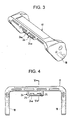
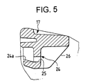
- a retained portion 24 to be engaged with the retaining pawl 22 is formed in the middle of the distal end of the lever 17.
- the retained portion 24 is formed integrally with the lever 17 in box-like form, with two inclined surface portions 24a projected from the inner surfaces thereof.
- the respective inclined surface portions 24a are arranged so as to correspond to the two hooking portions 22a of the retaining pawl 22.
- the inclination of each inclined surface portion 24a being such that the front side thereof (the left side as viewed in Fig. 1) is inclined upward, fits the angle of inclination of each hooking portion 22a.
- a surface on which the retained portion 24 is engaged with a retaining pawl 22 (a surface on which the inclined surface portions 24a contact the hooking portions 22a) is inclined in such a direction as to hamper retraction of the retaining pawl 22.
- On the rear sides of the respective inclined surface portions 24a are punched holes 25.
- a reinforcing rib 26 is formed between the punched holes 25 integrally with the lever 17.
- the hooking portions 22a of the retaining pawl 22 are, in the end, disengaged from the inclined surface portions 24a of the retained portion 24 to thereby unlock the lever 17.
- the cam follower pins 13 are displaced in a direction opposite to the inserting direction, when they are pressed by the cam grooves 18 in the lever 17, thereby disconnecting both connectors from each other while pushing the female connector housing 11 out of the hood portion 12a of the male connector housing 12.
- the lever 17 may happen to receive strong turning force toward the open position when the lever 17 is locked in the connected position for such a reason as the connectors being moved forcibly through electric wires or the like.
- the retained portion 24 of the lever 17 raises the retaining pawl 22 as is apparent from Fig. 1.
- the surface on which the retained portion 24 is engaged with the retaining pawl 22 (the surface on which the inclined surface portions 24a contact the hooking portions 22a) is inclined in such a direction as to hamper retraction of the retaining pawl 22. Therefore, even if the retaining pawl 22 is raised, the retaining pawl 22 is not displaced easily in the retracting direction (in a direction of the arrow in Fig.
Landscapes
- Details Of Connecting Devices For Male And Female Coupling (AREA)
Claims (2)
- Connecteur actionné par levier comportant :une paire de boîtiers de connecteur (11, 12) écartés l'un par rapport à l'autre pour être connectés ensemble par le mouvement rotatif d'un levier (17) à partir de position ouverte dans une position connectée;au moins une pointe (13) prévue sur un des boîtiers de connecteur (11, 12) pour être mise en prise avec au moins une rainure (18), ladite rainure (18) étant prévue dans ledit levier (17) qui est monté de manière à pouvoir tourner sur l'autre boîtier de connecteur (12, 11); etune partie de verrouillage du levier pour retenir ledit levier (17) dans la position connectée, ladite partie de verrouillage du levier comportant :une partie retenue (24) prévue sur ledit levier (17),et un cliquet d'arrêt (22) pour maintenir ladite partie retenue (24),caractérisé en ce queledit cliquet d'arrêt (22) est prévu sur ledit connecteur (11, 12);et une surface (24a) sur laquelle ladite partie retenue (24) est en prise avec ledit cliquet d'arrêt (22) est inclinée dans une direction telle à empêcher la rétraction dudit cliquet d'arrêt (22).
- Connecteur selon la revendication 1, comportant en plus un ressort de rappel pour pousser ledit levier (17) vers ladite position ouverte, et ladite rainure (18) comportant une zone de jeu de manière à permettre audit levier (17) de revenir dans un angle prédéterminé à partir de ladite position connectée vers ladite position ouverte, dans lequel ledit levier (17) est automatiquement amené dans une position debout par la force de poussée dudit ressort de rappel lorsque ledit levier (17) est dégagé de ladite partie de levier de verrouillage.
Priority Applications (1)
| Application Number | Priority Date | Filing Date | Title |
|---|---|---|---|
| EP96102377A EP0727847B1 (fr) | 1992-11-27 | 1993-11-25 | Connecteur actionné par levier |
Applications Claiming Priority (4)
| Application Number | Priority Date | Filing Date | Title |
|---|---|---|---|
| JP87679/92 | 1992-11-27 | ||
| JP1992087679U JP2574778Y2 (ja) | 1992-11-27 | 1992-11-27 | レバー式コネクタ |
| JP89541/92 | 1992-12-01 | ||
| JP8954192U JPH0648182U (ja) | 1992-12-01 | 1992-12-01 | レバー式コネクタ |
Related Child Applications (2)
| Application Number | Title | Priority Date | Filing Date |
|---|---|---|---|
| EP96102377.7 Division-Into | 1993-11-25 | ||
| EP96102377A Division EP0727847B1 (fr) | 1992-11-27 | 1993-11-25 | Connecteur actionné par levier |
Publications (2)
| Publication Number | Publication Date |
|---|---|
| EP0599332A1 EP0599332A1 (fr) | 1994-06-01 |
| EP0599332B1 true EP0599332B1 (fr) | 1997-03-19 |
Family
ID=26428926
Family Applications (2)
| Application Number | Title | Priority Date | Filing Date |
|---|---|---|---|
| EP93119060A Expired - Lifetime EP0599332B1 (fr) | 1992-11-27 | 1993-11-25 | Connecteur actionnée par levier |
| EP96102377A Expired - Lifetime EP0727847B1 (fr) | 1992-11-27 | 1993-11-25 | Connecteur actionné par levier |
Family Applications After (1)
| Application Number | Title | Priority Date | Filing Date |
|---|---|---|---|
| EP96102377A Expired - Lifetime EP0727847B1 (fr) | 1992-11-27 | 1993-11-25 | Connecteur actionné par levier |
Country Status (3)
| Country | Link |
|---|---|
| US (1) | US5474461A (fr) |
| EP (2) | EP0599332B1 (fr) |
| DE (2) | DE69308993T2 (fr) |
Cited By (1)
| Publication number | Priority date | Publication date | Assignee | Title |
|---|---|---|---|---|
| CN105610003A (zh) * | 2014-11-17 | 2016-05-25 | 住友电装株式会社 | 杆式连接器 |
Families Citing this family (43)
| Publication number | Priority date | Publication date | Assignee | Title |
|---|---|---|---|---|
| JP2882260B2 (ja) * | 1993-10-04 | 1999-04-12 | 住友電装株式会社 | レバー式コネクタ |
| GB9402570D0 (en) * | 1994-02-10 | 1994-04-06 | Amp Gmbh | Electrical connector having improved latching/unlatching feature |
| JP3000129B2 (ja) * | 1994-09-06 | 2000-01-17 | 矢崎総業株式会社 | レバー式コネクタ |
| JP2921647B2 (ja) * | 1994-11-22 | 1999-07-19 | 矢崎総業株式会社 | 低挿抜力コネクタのロック機構 |
| US5735702A (en) * | 1995-04-07 | 1998-04-07 | Sumitomo Wiring Systems, Ltd. | Lever type connector |
| EP1079473B1 (fr) * | 1995-10-24 | 2003-03-12 | Sumitomo Wiring Systems, Ltd. | Connecteur à levier de verrouillage |
| JP3075164B2 (ja) * | 1996-01-16 | 2000-08-07 | 住友電装株式会社 | レバー式コネクタ |
| US5806176A (en) * | 1996-02-05 | 1998-09-15 | Raychem Corporation | Insertion tool and method of use |
| JP3472666B2 (ja) * | 1996-07-24 | 2003-12-02 | 矢崎総業株式会社 | コネクタ |
| JP3275290B2 (ja) * | 1996-08-09 | 2002-04-15 | 住友電装株式会社 | レバー式コネクタ |
| JP3468007B2 (ja) * | 1997-02-05 | 2003-11-17 | 住友電装株式会社 | レバー式コネクタ |
| DE29800831U1 (de) * | 1998-01-20 | 1998-04-02 | PFT Putz- und Fördertechnik GmbH & Co. KG, 97346 Iphofen | Horizontalmischer für Mörtel |
| JP3252955B2 (ja) * | 1998-05-21 | 2002-02-04 | 住友電装株式会社 | レバー式コネクタ |
| US6183278B1 (en) * | 2000-01-14 | 2001-02-06 | Yazaki Corporation | Lever structure of electric connection box |
| JP4047510B2 (ja) * | 2000-03-02 | 2008-02-13 | 株式会社東海理化電機製作所 | コネクタ装置 |
| GB0027758D0 (en) * | 2000-11-14 | 2000-12-27 | Delphi Tech Inc | Two-part electrical connector |
| USD459702S1 (en) | 2001-01-12 | 2002-07-02 | Japan Aviation Electronics Industry, Limited | Electrical connector |
| US7070438B2 (en) * | 2004-03-31 | 2006-07-04 | Jst Corporation | Connector lever lock |
| JP4229282B2 (ja) * | 2004-04-28 | 2009-02-25 | タイコエレクトロニクスアンプ株式会社 | レバー式コネクタ |
| DE102005050625B4 (de) * | 2004-10-22 | 2011-07-28 | Sumitomo Wiring Systems, Ltd., Mie | Verbinder und Verbinderanordnung |
| US7255580B2 (en) * | 2005-03-09 | 2007-08-14 | Tyco Electronics Corporation | Electrical connector and electrical connector assembly having lever assist with latch hold down mechanism |
| US7261575B2 (en) * | 2005-03-09 | 2007-08-28 | Tyco Electronics Corporation | Electrical connector and electrical connector assembly having selectively includable lever assist |
| US7052294B1 (en) * | 2005-04-15 | 2006-05-30 | J.S.T. Corporation | Electrical connector with a locking mechanism |
| JP2006344473A (ja) * | 2005-06-08 | 2006-12-21 | Sumitomo Wiring Syst Ltd | レバー式コネクタ |
| USD547269S1 (en) * | 2006-01-20 | 2007-07-24 | Sumitomo Wiring Systems, Ltd. | Electrical connector housing |
| JP5009538B2 (ja) * | 2006-02-02 | 2012-08-22 | 矢崎総業株式会社 | レバー式コネクタ |
| JP4791328B2 (ja) * | 2006-10-27 | 2011-10-12 | 矢崎総業株式会社 | レバー式コネクタ |
| JP5162348B2 (ja) * | 2008-06-25 | 2013-03-13 | 矢崎総業株式会社 | レバー式コネクタ |
| USD671897S1 (en) * | 2011-03-25 | 2012-12-04 | Phoenix Contact Gmbh & Co. Kg | Electrical connector with a lock and release aid |
| USD696202S1 (en) | 2011-03-25 | 2013-12-24 | Phoenix Contact Gmbh & Co. Kg | Lock and release aid for an electrical connector |
| CN102891397B (zh) * | 2012-09-19 | 2016-05-18 | 中航光电科技股份有限公司 | 一种具有锁紧功能的矩形电连接器及其组件 |
| JP2016009597A (ja) * | 2014-06-24 | 2016-01-18 | 日本航空電子工業株式会社 | コネクタ |
| JP2019003916A (ja) * | 2017-06-20 | 2019-01-10 | 矢崎総業株式会社 | サービスプラグ |
| JP2019091608A (ja) * | 2017-11-14 | 2019-06-13 | 住友電装株式会社 | コネクタ |
| JP2019091609A (ja) * | 2017-11-14 | 2019-06-13 | 住友電装株式会社 | コネクタ |
| JP2019091610A (ja) | 2017-11-14 | 2019-06-13 | 住友電装株式会社 | コネクタ |
| EP3579354B1 (fr) * | 2018-06-05 | 2021-11-17 | Ningbo Geely Automobile Research & Development Co. Ltd. | Connecteur électrique haute tension |
| CN208797213U (zh) * | 2018-06-08 | 2019-04-26 | 安费诺电子装配(厦门)有限公司 | 一种带旋转锁杆的线端连接器及连接器组件 |
| FR3084532B1 (fr) * | 2018-07-27 | 2023-05-12 | Delphi Int Operations Luxembourg Sarl | Connecteur avec levier d'assistance a la connexion et procede de conditionnement d'un tel connecteur |
| DE102019116146A1 (de) * | 2019-06-13 | 2020-12-17 | Harting Electric Gmbh & Co. Kg | Selbstverrastender Verriegelungsbügel für einen Steckverbinder |
| JP7525309B2 (ja) * | 2020-06-03 | 2024-07-30 | タイコエレクトロニクスジャパン合同会社 | コネクタおよびコネクタ組立体 |
| USD991025S1 (en) * | 2022-08-03 | 2023-07-04 | Kinetix Ag | Mounting device |
| WO2025251312A1 (fr) * | 2024-06-07 | 2025-12-11 | Robert Bosch Gmbh | Connecteur enfichable et ensemble connecteur enfichable |
Family Cites Families (16)
| Publication number | Priority date | Publication date | Assignee | Title |
|---|---|---|---|---|
| DE1590736A1 (de) * | 1965-07-31 | 1970-06-25 | Tesla Np | Steckverbindung |
| DE3527916A1 (de) * | 1985-08-03 | 1987-02-12 | Cannon Electric Gmbh | Elektrische steckerkupplung |
| US4634204A (en) * | 1985-12-24 | 1987-01-06 | General Motors Corporation | Electrical connector with connector position assurance/assist device |
| US4714433A (en) * | 1987-01-21 | 1987-12-22 | General Motors Corporation | Electrical connector with position assurance and double lock |
| US5135410A (en) * | 1990-05-30 | 1992-08-04 | Sumitomo Wiring Systems, Ltd. | Electric connector assembly |
| JP2525502B2 (ja) * | 1990-05-30 | 1996-08-21 | 矢崎総業株式会社 | 電気コネクタ |
| US5139430A (en) * | 1990-06-28 | 1992-08-18 | Digital Equipment Corporation | PCB insertion/ejection lever mechanism |
| JP2971531B2 (ja) * | 1990-06-29 | 1999-11-08 | 住友電装株式会社 | コネクタの結合構造 |
| JP2501005Y2 (ja) * | 1990-10-31 | 1996-06-12 | 矢崎総業株式会社 | コネクタ |
| JP2500247Y2 (ja) * | 1991-06-03 | 1996-06-05 | 矢崎総業株式会社 | レバ―付コネクタ |
| JP2538723B2 (ja) * | 1991-06-25 | 1996-10-02 | 矢崎総業株式会社 | レバ―付コネクタ |
| JP2624049B2 (ja) * | 1991-09-13 | 1997-06-25 | 住友電装株式会社 | コネクタ |
| GB2260865B (en) * | 1991-10-21 | 1996-03-27 | Sumitomo Wall Systems Ltd | Lever type connector |
| JP2598412Y2 (ja) * | 1992-04-03 | 1999-08-09 | 矢崎総業株式会社 | 低挿抜力コネクタ |
| JP2598090Y2 (ja) * | 1992-04-28 | 1999-07-26 | 住友電装株式会社 | レバー式コネクタ |
| GB9219322D0 (en) * | 1992-09-11 | 1992-10-28 | Dzus Fastener Europe | Lever mechanism |
-
1993
- 1993-11-25 EP EP93119060A patent/EP0599332B1/fr not_active Expired - Lifetime
- 1993-11-25 EP EP96102377A patent/EP0727847B1/fr not_active Expired - Lifetime
- 1993-11-25 DE DE69308993T patent/DE69308993T2/de not_active Expired - Lifetime
- 1993-11-25 DE DE69320662T patent/DE69320662T2/de not_active Expired - Lifetime
- 1993-11-26 US US08/157,539 patent/US5474461A/en not_active Expired - Lifetime
Cited By (1)
| Publication number | Priority date | Publication date | Assignee | Title |
|---|---|---|---|---|
| CN105610003A (zh) * | 2014-11-17 | 2016-05-25 | 住友电装株式会社 | 杆式连接器 |
Also Published As
| Publication number | Publication date |
|---|---|
| DE69308993D1 (de) | 1997-04-24 |
| DE69308993T2 (de) | 1997-11-06 |
| EP0727847A3 (fr) | 1997-01-08 |
| DE69320662T2 (de) | 1999-02-25 |
| EP0727847B1 (fr) | 1998-08-26 |
| EP0599332A1 (fr) | 1994-06-01 |
| US5474461A (en) | 1995-12-12 |
| DE69320662D1 (de) | 1998-10-01 |
| EP0727847A2 (fr) | 1996-08-21 |
Similar Documents
| Publication | Publication Date | Title |
|---|---|---|
| EP0599332B1 (fr) | Connecteur actionnée par levier | |
| US5938470A (en) | Half-fitting prevention connector | |
| JP3027487B2 (ja) | 低挿抜力コネクタのロック機構 | |
| EP1369964B1 (fr) | Dispositif pour assurer la position du connecteur | |
| EP0790676B1 (fr) | Connecteur du type à levier | |
| US5823813A (en) | Connector position assurance device | |
| CA2168399C (fr) | Connecteur pour carte de circuits imprimes | |
| US7255581B2 (en) | Lever-type connector | |
| EP2276123B1 (fr) | Connecteur de type à levier | |
| KR0125801B1 (ko) | 전기 커넥터 | |
| EP0501502B1 (fr) | Connecteur à force d'insertion/extraction faible | |
| JP3841389B2 (ja) | コネクタ嵌合構造 | |
| JPH03116672A (ja) | 電気コネクタ | |
| US6811437B2 (en) | Connector and method of mounting it | |
| JP3275290B2 (ja) | レバー式コネクタ | |
| US5609494A (en) | Connector lever locking mechanism | |
| JPH08148221A (ja) | 低挿抜力コネクタのロック機構 | |
| EP0809203B1 (fr) | Connecteur de carte capable de prévenir des dommages aux objets et aux contacts et réalisant une connexion d'une excellente faibilité | |
| EP1047155B1 (fr) | Connecteur du type à levier | |
| EP0774802B1 (fr) | Connecteur électrique avec élément élastique interne | |
| GB2398184A (en) | Card connector locking cam | |
| EP0727846B1 (fr) | Connecteur du type a levier | |
| EP0883212B1 (fr) | Structure d'engagement d'un connecteur | |
| EP0954061B1 (fr) | Un connecteur | |
| JP3320365B2 (ja) | カード用電気コネクタ |
Legal Events
| Date | Code | Title | Description |
|---|---|---|---|
| PUAI | Public reference made under article 153(3) epc to a published international application that has entered the european phase |
Free format text: ORIGINAL CODE: 0009012 |
|
| AK | Designated contracting states |
Kind code of ref document: A1 Designated state(s): DE GB |
|
| 17P | Request for examination filed |
Effective date: 19940830 |
|
| 17Q | First examination report despatched |
Effective date: 19950310 |
|
| GRAG | Despatch of communication of intention to grant |
Free format text: ORIGINAL CODE: EPIDOS AGRA |
|
| GRAH | Despatch of communication of intention to grant a patent |
Free format text: ORIGINAL CODE: EPIDOS IGRA |
|
| GRAH | Despatch of communication of intention to grant a patent |
Free format text: ORIGINAL CODE: EPIDOS IGRA |
|
| GRAA | (expected) grant |
Free format text: ORIGINAL CODE: 0009210 |
|
| AK | Designated contracting states |
Kind code of ref document: B1 Designated state(s): DE GB |
|
| DX | Miscellaneous (deleted) | ||
| REF | Corresponds to: |
Ref document number: 69308993 Country of ref document: DE Date of ref document: 19970424 |
|
| PLBE | No opposition filed within time limit |
Free format text: ORIGINAL CODE: 0009261 |
|
| STAA | Information on the status of an ep patent application or granted ep patent |
Free format text: STATUS: NO OPPOSITION FILED WITHIN TIME LIMIT |
|
| 26N | No opposition filed | ||
| REG | Reference to a national code |
Ref country code: GB Ref legal event code: IF02 |
|
| PGFP | Annual fee paid to national office [announced via postgrant information from national office to epo] |
Ref country code: GB Payment date: 20081119 Year of fee payment: 16 |
|
| PGFP | Annual fee paid to national office [announced via postgrant information from national office to epo] |
Ref country code: DE Payment date: 20091119 Year of fee payment: 17 |
|
| GBPC | Gb: european patent ceased through non-payment of renewal fee |
Effective date: 20091125 |
|
| PG25 | Lapsed in a contracting state [announced via postgrant information from national office to epo] |
Ref country code: GB Free format text: LAPSE BECAUSE OF NON-PAYMENT OF DUE FEES Effective date: 20091125 |
|
| REG | Reference to a national code |
Ref country code: DE Ref legal event code: R119 Ref document number: 69308993 Country of ref document: DE Effective date: 20110601 Ref country code: DE Ref legal event code: R119 Ref document number: 69308993 Country of ref document: DE Effective date: 20110531 |
|
| PG25 | Lapsed in a contracting state [announced via postgrant information from national office to epo] |
Ref country code: DE Free format text: LAPSE BECAUSE OF NON-PAYMENT OF DUE FEES Effective date: 20110531 |