EP0599609A1 - Frequenzsynthetisierer für ein Kommunikationssystem - Google Patents
Frequenzsynthetisierer für ein Kommunikationssystem Download PDFInfo
- Publication number
- EP0599609A1 EP0599609A1 EP93309345A EP93309345A EP0599609A1 EP 0599609 A1 EP0599609 A1 EP 0599609A1 EP 93309345 A EP93309345 A EP 93309345A EP 93309345 A EP93309345 A EP 93309345A EP 0599609 A1 EP0599609 A1 EP 0599609A1
- Authority
- EP
- European Patent Office
- Prior art keywords
- frequency
- phase
- signal
- synthesizing apparatus
- frequency signal
- Prior art date
- Legal status (The legal status is an assumption and is not a legal conclusion. Google has not performed a legal analysis and makes no representation as to the accuracy of the status listed.)
- Withdrawn
Links
Images

Classifications
-
- H—ELECTRICITY
- H03—ELECTRONIC CIRCUITRY
- H03L—AUTOMATIC CONTROL, STARTING, SYNCHRONISATION OR STABILISATION OF GENERATORS OF ELECTRONIC OSCILLATIONS OR PULSES
- H03L7/00—Automatic control of frequency or phase; Synchronisation
- H03L7/06—Automatic control of frequency or phase; Synchronisation using a reference signal applied to a frequency- or phase-locked loop
- H03L7/16—Indirect frequency synthesis, i.e. generating a desired one of a number of predetermined frequencies using a frequency- or phase-locked loop
- H03L7/18—Indirect frequency synthesis, i.e. generating a desired one of a number of predetermined frequencies using a frequency- or phase-locked loop using a frequency divider or counter in the loop
- H03L7/1806—Indirect frequency synthesis, i.e. generating a desired one of a number of predetermined frequencies using a frequency- or phase-locked loop using a frequency divider or counter in the loop the frequency divider comprising a phase accumulator generating the frequency divided signal
Definitions
- the present invention relates to a frequency synthesizing apparatus for use in a microwave, mobile or similar communication system.
- a number of carriers are often arranged at relatively narrow frequency intervals to provide large capacity communication system.
- receivers and repeaters included in the system should have function to perform frequency acquisition surely and rapidly. It has been customary to provide receivers and repeaters equipped with a frequency synthesizing apparatus using a phase-locked loop (PLL) circuit.
- PLL phase-locked loop
- Fig. 1 shows a conventional frequency synthesizing apparatus using a PLL circuit as mentioned above.
- the apparatus includes a voltage controlled oscillator (VCO) 9, a variable (programable) frequency divider 10 for dividing the output frequency of the VCO 9 to produce a phase-comparative frequency signal, a reference frequency oscillator 6 for generating a reference frequency signal, a phase comparator 7 for comparing the phase of the reference frequency signal and the phase of the phase-comparative frequency signal from the frequency divider 10 and a loop amplifier 8 having a desired loop filtering characteristic.
- the variable frequency divider 10 is composed of an integral frequency divider.
- the problem with the synthesizing apparatus using the integral frequency divider is that when the output frequency signal is to be changed, a step frequency should not be lower than the comparative frequency in the phase comparator 7. Conversely, if a PLL having a low step frequency is designed, the comparative frequency in the phase comparator 7 is lowered, resulting in the following problems:
- a preferred frequency synthesizing apparatus embodying the present invention comprises a voltage controlled oscillator (VCO), a direct digital synthesizer for receiving an output of the VCO as an input clock frequency and for dividing the frequency of the input clock frequency to thereby generate a phase-comparative frequency signal, a reference frequency oscillator for generating the reference frequency signal, a phase comparator for comparing the phase of the phase-comparative frequency signal and the phase of the reference frequency signal to thereby produce a phase error signal, and a loop amplifier receiving the phase error signal for filtering it with a desired response characteristic of a loop to generate a control signal.
- the direct digital synthesizer can divide the input clock frequency by a decimal or non-integral value.
- the preferred frequency synthesizing apparatus is capable of reducing the step of the output frequency without lowering the reference frequency and the comparative frequency. It allows the phase-comparative frequency of the PLL to be selected freely without the restriction that it is below the step frequency. It also permits the broad loop band for the PLL and thereby rapid frequency acquisition.
- a frequency synthesizing apparatus embodying the present invention includes a VCO 4.
- a direct digital synthesizer 5 receives the output f c (Hz) of the VCO 4 at the clock input terminal thereof and converts it to phase-comparative reference frequency f o (Hz).
- the synthesizer 5 is capable of dividing the input by a decimal i.e. a non-integer value. If the Eq. (1) and a sampling theorem is satisfied, the clock frequency can be converted to any desired phase-comparative frequency.
- a phase comparator 2 compares the output of the direct digital synthesizer 5 with a reference frequency signal generated by a reference frequency oscillator 1, thereby producing a phase error signal.
- the phase error signal is fed back to the VCO as its control signal 4 via a loop amplifier 3 which sets a desired loop filtering characteristic.
- the direct digital synthesizer 5 will be described specifically with reference to Fig. 3.
- the synthesizer 5 has a frequency data setting circuit 10 for designating data indicative of the above-mentioned number n (binary).
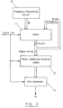
- the number n is fed to an adder 11 having a predetermined number of bits (sixteen bits in the embodiment) which predetermined number corresponds to the accumulating bit number m .
- the adder 11 adds the data of the number n to the output thereof in synchronism with the clock CK of the frequency f c .
- the adder 11 has a function of integrating, i.e., accumulating the constant n with respect to time.
- the data of the saw-tooth waveform change are fed from the adder 11 to a phase-to-amplitude converter 12. It is noted that, in this embodiment, only several higher bits, eight bits in the embodiment, of the adder 11 are applied to the phase-to-amplitude converter 12.
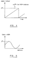
- the phase-to-amplitude converter 12 is implemented by a ROM (Read Only Memory); Fig. 5 indicates a relation between the addresses of the ROM and the data stored therein.
- One period of the sinusoidal waveform shown in Fig. 5 corresponds to one period of the saw-tooth waveform shown in Fig. 4. Therefore, the frequency of the sinusoidal waveform is controlled by the above-mentioned constant n and given by the Eq. (1). It is noted here that the ratio between f o and f c is not always an integer, i.e., the direct digital synthesizer 5 has a decimal dividing function.
- a digital-to-analog converter (DAC) 13 converts the output of the phase-to-amplitude converter (ROM) 12, i.e., the sinusoidal wave amplitude data, to an analog sinusoidal waveform in synchronism with the clock CK. Equivalently, therefore, the DAC 13 reproduces the sinusoidal waveform sampled at the frequency f c . It follows that a condition 2f o ⁇ f c is derived from the sampling theorem.
- the direct digital synthesizer 5 performs the frequency conversion as represented by the Eq. (1).
- the direct digital synthesizer 5 is introduced in the PLL to constitute a frequency synthesizing apparatus.
- the decimal dividing function of the direct digital synthesizer 5 enables the frequency synthesizing apparatus to have a narrow step frequency, while maintaining the phase-comparative frequency high. This is successful in eliminating the prior art problems discussed previously.
- the phase-comparative frequency f o is 1 MHz
- the accumulator width m is sixteen.
- the output frequency f c of the VCO is 4 MHz when n is 16,384, and 4.00024415 ... MHz when n is 16,383, as determined by the Eq. (1).
- a frequency synthesizing apparatus whose step frequency is as low as 244.15 Hz is achieved.
- the direct digital synthesizer 5 is provided with a 32-bit accumulator and the output of the VCO 4 is 6 GHz, even a frequency synthesizing apparatus variable on a 1.4 Hz step basis can be implemented.
- the present system provides a frequency synthesizing apparatus having a direct digital synthesizer in a PLL thereof and, therefore, achieves various unprecedented advantages, as enumerated below.
Landscapes
- Stabilization Of Oscillater, Synchronisation, Frequency Synthesizers (AREA)
Applications Claiming Priority (2)
| Application Number | Priority Date | Filing Date | Title |
|---|---|---|---|
| JP315008/92 | 1992-11-25 | ||
| JP4315008A JPH06164388A (ja) | 1992-11-25 | 1992-11-25 | 周波数シンセサイザー |
Publications (1)
| Publication Number | Publication Date |
|---|---|
| EP0599609A1 true EP0599609A1 (de) | 1994-06-01 |
Family
ID=18060313
Family Applications (1)
| Application Number | Title | Priority Date | Filing Date |
|---|---|---|---|
| EP93309345A Withdrawn EP0599609A1 (de) | 1992-11-25 | 1993-11-24 | Frequenzsynthetisierer für ein Kommunikationssystem |
Country Status (2)
| Country | Link |
|---|---|
| EP (1) | EP0599609A1 (de) |
| JP (1) | JPH06164388A (de) |
Cited By (6)
| Publication number | Priority date | Publication date | Assignee | Title |
|---|---|---|---|---|
| DE19619408A1 (de) * | 1996-05-14 | 1997-11-20 | Plath Naut Elektron Tech | Frequenzsyntheseschaltung mit verkürzten Umschaltzeiten |
| EP0866560A1 (de) * | 1997-03-21 | 1998-09-23 | Tektronix, Inc. | Verbesserter digitaler Taktgenerator |
| WO1998045950A1 (de) * | 1997-04-07 | 1998-10-15 | Siemens Aktiengesellschaft | Digitale afc-einstellung durch reziproke dds |
| EP0945715A3 (de) * | 1998-03-27 | 2002-07-24 | EADS Deutschland Gmbh | Anordnung zur präzisen Entfernungsmessung, insbesondere zur Füllstandsmessung |
| EP0963075A3 (de) * | 1998-06-02 | 2004-01-07 | Victor Company Of Japan, Ltd. | Taktsignalerzeugungsvorrichtung |
| WO2008006818A3 (de) * | 2006-07-13 | 2008-06-12 | Siemens Ag | Radaranordnung |
Families Citing this family (1)
| Publication number | Priority date | Publication date | Assignee | Title |
|---|---|---|---|---|
| US7834713B2 (en) | 2008-02-29 | 2010-11-16 | Itt Manufacturing Enterprises, Inc. | Synthesized local oscillator and method of operation thereof |
Citations (3)
| Publication number | Priority date | Publication date | Assignee | Title |
|---|---|---|---|---|
| EP0388313A2 (de) * | 1989-03-17 | 1990-09-19 | John Fluke Mfg. Co., Inc. | Kohärenter direkter digitaler Synthesizer |
| US4965533A (en) * | 1989-08-31 | 1990-10-23 | Qualcomm, Inc. | Direct digital synthesizer driven phase lock loop frequency synthesizer |
| EP0454917A1 (de) * | 1990-05-02 | 1991-11-06 | Hewlett-Packard Limited | Frequenzsynthesizer |
-
1992
- 1992-11-25 JP JP4315008A patent/JPH06164388A/ja active Pending
-
1993
- 1993-11-24 EP EP93309345A patent/EP0599609A1/de not_active Withdrawn
Patent Citations (3)
| Publication number | Priority date | Publication date | Assignee | Title |
|---|---|---|---|---|
| EP0388313A2 (de) * | 1989-03-17 | 1990-09-19 | John Fluke Mfg. Co., Inc. | Kohärenter direkter digitaler Synthesizer |
| US4965533A (en) * | 1989-08-31 | 1990-10-23 | Qualcomm, Inc. | Direct digital synthesizer driven phase lock loop frequency synthesizer |
| EP0454917A1 (de) * | 1990-05-02 | 1991-11-06 | Hewlett-Packard Limited | Frequenzsynthesizer |
Cited By (10)
| Publication number | Priority date | Publication date | Assignee | Title |
|---|---|---|---|---|
| DE19619408A1 (de) * | 1996-05-14 | 1997-11-20 | Plath Naut Elektron Tech | Frequenzsyntheseschaltung mit verkürzten Umschaltzeiten |
| DE19619408C2 (de) * | 1996-05-14 | 2002-06-27 | Plath Naut Elektron Tech | Frequenzsyntheseschaltung mit verkürzten Umschaltzeiten |
| EP0866560A1 (de) * | 1997-03-21 | 1998-09-23 | Tektronix, Inc. | Verbesserter digitaler Taktgenerator |
| WO1998045950A1 (de) * | 1997-04-07 | 1998-10-15 | Siemens Aktiengesellschaft | Digitale afc-einstellung durch reziproke dds |
| US6104252A (en) * | 1997-04-07 | 2000-08-15 | Siemens Aktiengesellschaft | Circuit for automatic frequency control using a reciprocal direct digital synthesis |
| EP0945715A3 (de) * | 1998-03-27 | 2002-07-24 | EADS Deutschland Gmbh | Anordnung zur präzisen Entfernungsmessung, insbesondere zur Füllstandsmessung |
| US6486826B1 (en) | 1998-03-27 | 2002-11-26 | Eads Deutschland Gmbh | Arrangement for the precise distance measuring, in particular the filling level measuring |
| EP0963075A3 (de) * | 1998-06-02 | 2004-01-07 | Victor Company Of Japan, Ltd. | Taktsignalerzeugungsvorrichtung |
| WO2008006818A3 (de) * | 2006-07-13 | 2008-06-12 | Siemens Ag | Radaranordnung |
| US7990313B2 (en) | 2006-07-13 | 2011-08-02 | Siemens Aktiengesellschaft | Radar arrangement |
Also Published As
| Publication number | Publication date |
|---|---|
| JPH06164388A (ja) | 1994-06-10 |
Similar Documents
| Publication | Publication Date | Title |
|---|---|---|
| EP0961412B1 (de) | Frequenzsynthetisierer | |
| US6198353B1 (en) | Phase locked loop having direct digital synthesizer dividers and improved phase detector | |
| US5821816A (en) | Integer division variable frequency synthesis apparatus and method | |
| US5065408A (en) | Fractional-division synthesizer for a voice/data communications systems | |
| US4516084A (en) | Frequency synthesizer using an arithmetic frequency synthesizer and plural phase locked loops | |
| US4926130A (en) | Synchronous up-conversion direct digital synthesizer | |
| JP2650492B2 (ja) | 変調スプリアス補償を有する分数nシンセサイザ | |
| US5111162A (en) | Digital frequency synthesizer having AFC and modulation applied to frequency divider | |
| US5329253A (en) | Frequency synthesis using frequency controlled carrier modulated with PLL feedback signal | |
| EP0492588B1 (de) | Verfahren zum Nachführen einer Trägerfrequenz. | |
| EP0419622B1 (de) | Frequenzsynthesizer mit gebrochenem teilverhältnis | |
| US5831481A (en) | Phase lock loop circuit having a broad loop band and small step frequency | |
| US5184092A (en) | Phase-locked loop frequency tracking device including a direct digital synthesizer | |
| US4185247A (en) | Means for reducing spurious frequencies in a direct frequency synthesizer | |
| JPH0645929A (ja) | 半分の整数による分割器およびアナログ利得補償を使用した低雑音周波数シンセサイザ | |
| EP0599609A1 (de) | Frequenzsynthetisierer für ein Kommunikationssystem | |
| EP0459446B1 (de) | Digital gesteuerter Oszillator | |
| US5673007A (en) | Frequency synthesizer having PLL receiving filtered output of DDS | |
| US5272454A (en) | Digital FM modulator using direct digital synthesizer | |
| Noel et al. | Frequency synthesis: A comparison of techniques | |
| EP0454917A1 (de) | Frequenzsynthesizer | |
| KR0149126B1 (ko) | 혼합형 주파수 합성기 | |
| GB2091960A (en) | High speed frequency synthesizer | |
| AU631300B2 (en) | Phase-locked loop type frequency synthesizer having improved loop response | |
| GB2267401A (en) | Frequency synthesizer |
Legal Events
| Date | Code | Title | Description |
|---|---|---|---|
| PUAI | Public reference made under article 153(3) epc to a published international application that has entered the european phase |
Free format text: ORIGINAL CODE: 0009012 |
|
| 17P | Request for examination filed |
Effective date: 19940208 |
|
| AK | Designated contracting states |
Kind code of ref document: A1 Designated state(s): DE FR GB |
|
| 17Q | First examination report despatched |
Effective date: 19950726 |
|
| 18D | Application deemed to be withdrawn |
Effective date: 19951206 |