EP0601209A1 - Wärmetauscher mit maschigen kühlrippen sowie verfahren zu dessen herstellung - Google Patents
Wärmetauscher mit maschigen kühlrippen sowie verfahren zu dessen herstellung Download PDFInfo
- Publication number
- EP0601209A1 EP0601209A1 EP93914936A EP93914936A EP0601209A1 EP 0601209 A1 EP0601209 A1 EP 0601209A1 EP 93914936 A EP93914936 A EP 93914936A EP 93914936 A EP93914936 A EP 93914936A EP 0601209 A1 EP0601209 A1 EP 0601209A1
- Authority
- EP
- European Patent Office
- Prior art keywords
- heat transfer
- fins
- portions
- mesh
- transfer tube
- Prior art date
- Legal status (The legal status is an assumption and is not a legal conclusion. Google has not performed a legal analysis and makes no representation as to the accuracy of the status listed.)
- Granted
Links
- 238000004519 manufacturing process Methods 0.000 title claims description 6
- 238000000034 method Methods 0.000 title description 13
- 238000005304 joining Methods 0.000 claims abstract description 16
- 238000003825 pressing Methods 0.000 claims description 3
- 239000000470 constituent Substances 0.000 abstract 2
- 239000012530 fluid Substances 0.000 description 11
- 239000003507 refrigerant Substances 0.000 description 6
- 230000000694 effects Effects 0.000 description 3
- 238000003466 welding Methods 0.000 description 2
- 238000005219 brazing Methods 0.000 description 1
- 238000010276 construction Methods 0.000 description 1
- 230000002093 peripheral effect Effects 0.000 description 1
- 230000000717 retained effect Effects 0.000 description 1
- 238000005476 soldering Methods 0.000 description 1
- 125000006850 spacer group Chemical group 0.000 description 1
Images

Classifications
-
- F—MECHANICAL ENGINEERING; LIGHTING; HEATING; WEAPONS; BLASTING
- F28—HEAT EXCHANGE IN GENERAL
- F28F—DETAILS OF HEAT-EXCHANGE AND HEAT-TRANSFER APPARATUS, OF GENERAL APPLICATION
- F28F1/00—Tubular elements; Assemblies of tubular elements
- F28F1/10—Tubular elements and assemblies thereof with means for increasing heat-transfer area, e.g. with fins, with projections, with recesses
- F28F1/12—Tubular elements and assemblies thereof with means for increasing heat-transfer area, e.g. with fins, with projections, with recesses the means being only outside the tubular element
- F28F1/14—Tubular elements and assemblies thereof with means for increasing heat-transfer area, e.g. with fins, with projections, with recesses the means being only outside the tubular element and extending longitudinally
- F28F1/22—Tubular elements and assemblies thereof with means for increasing heat-transfer area, e.g. with fins, with projections, with recesses the means being only outside the tubular element and extending longitudinally the means having portions engaging further tubular elements
-
- F—MECHANICAL ENGINEERING; LIGHTING; HEATING; WEAPONS; BLASTING
- F28—HEAT EXCHANGE IN GENERAL
- F28F—DETAILS OF HEAT-EXCHANGE AND HEAT-TRANSFER APPARATUS, OF GENERAL APPLICATION
- F28F1/00—Tubular elements; Assemblies of tubular elements
- F28F1/10—Tubular elements and assemblies thereof with means for increasing heat-transfer area, e.g. with fins, with projections, with recesses
- F28F1/12—Tubular elements and assemblies thereof with means for increasing heat-transfer area, e.g. with fins, with projections, with recesses the means being only outside the tubular element
- F28F1/122—Tubular elements and assemblies thereof with means for increasing heat-transfer area, e.g. with fins, with projections, with recesses the means being only outside the tubular element and being formed of wires
-
- F—MECHANICAL ENGINEERING; LIGHTING; HEATING; WEAPONS; BLASTING
- F28—HEAT EXCHANGE IN GENERAL
- F28F—DETAILS OF HEAT-EXCHANGE AND HEAT-TRANSFER APPARATUS, OF GENERAL APPLICATION
- F28F1/00—Tubular elements; Assemblies of tubular elements
- F28F1/10—Tubular elements and assemblies thereof with means for increasing heat-transfer area, e.g. with fins, with projections, with recesses
- F28F1/42—Tubular elements and assemblies thereof with means for increasing heat-transfer area, e.g. with fins, with projections, with recesses the means being both outside and inside the tubular element
- F28F1/44—Tubular elements and assemblies thereof with means for increasing heat-transfer area, e.g. with fins, with projections, with recesses the means being both outside and inside the tubular element and being formed of wire mesh
-
- F—MECHANICAL ENGINEERING; LIGHTING; HEATING; WEAPONS; BLASTING
- F28—HEAT EXCHANGE IN GENERAL
- F28F—DETAILS OF HEAT-EXCHANGE AND HEAT-TRANSFER APPARATUS, OF GENERAL APPLICATION
- F28F3/00—Plate-like or laminated elements; Assemblies of plate-like or laminated elements
- F28F3/02—Elements or assemblies thereof with means for increasing heat-transfer area, e.g. with fins, with recesses, with corrugations
- F28F3/022—Elements or assemblies thereof with means for increasing heat-transfer area, e.g. with fins, with recesses, with corrugations the means being wires or pins
-
- Y—GENERAL TAGGING OF NEW TECHNOLOGICAL DEVELOPMENTS; GENERAL TAGGING OF CROSS-SECTIONAL TECHNOLOGIES SPANNING OVER SEVERAL SECTIONS OF THE IPC; TECHNICAL SUBJECTS COVERED BY FORMER USPC CROSS-REFERENCE ART COLLECTIONS [XRACs] AND DIGESTS
- Y10—TECHNICAL SUBJECTS COVERED BY FORMER USPC
- Y10T—TECHNICAL SUBJECTS COVERED BY FORMER US CLASSIFICATION
- Y10T29/00—Metal working
- Y10T29/49—Method of mechanical manufacture
- Y10T29/4935—Heat exchanger or boiler making
- Y10T29/49377—Tube with heat transfer means
- Y10T29/49378—Finned tube
Definitions
- the present invention relates to a mesh fin type heat exchanger including a multiplicity of heat transfer tubes arranged in parallel and a multiplicity of mesh-form fins arranged parallel to the axes of the heat transfer tubes and joined to the heat transfer tubes, and to a method of making the same.
- Heat exchangers of a cross fin coil type have hitherto been widely used which has a multiplicity of heat transfer tubes arranged in parallel and a multiplicity of lamellar fins arranged orthogonally to the heat transfer tubes.
- it has been conventional to work the fins in various ways as, for example, by providing notched and bent pieces of various configurations on the surfaces of the fins).
- such fin working have a limitation on the effectiveness for the improvement of the heat transfer performance.
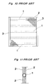
- a heat exchanger of the mesh fin type as illustrated in Figs. 10 and 11, comprises a multiplicity of heat transfer tubes 1, 1 ... arranged in parallel, a multiplicity of mesh-form fins 2, 2 ... arranged parallel to the axes of the heat transfer tubes 1, 1 ... and joined to the outer peripheries of the heat transfer tubes 1, and tube plates 3 supporting the heat transfer tubes 1, 1 ... at the ends thereof.
- the heat transfer tubes 1 and the mesh-form fins 2 are joined together usually by soldering or brazing after the mesh-form fins 2, 2 ... are tightly held against the heat transfer tubes 1 from opposite sides thereof.
- the present invention has been made in view of the above noted problems and it is an object of the invention to provide for improvement in the process of assembling heat transfer tubes and mesh-form fins together.
- the mesh fin type heat exchanger according to claim 1 is a mesh fin type heat exchanger by comprising a plurality of heat transfer tubes arranged in parallel and a plurality of mesh-form fins arranged parallel to axes of the heat transfer tubes thereof and joined to the heat transfer tubes, characterized in that each of the heat transfer tubes consists of a pair of tube component members having a half cylindrical configuration, the tube component members having, at their respective circumferential ends, joint portions extending along the axis of the heat transfer tube, the opposed joint portions of the tube component members being joined together externally of the fins in such a way as to sandwich the fins between them.
- the mesh fin type heat exchanger of claim 2 is characterized in that the fins are arranged so that a part of the fins extends through the heat transfer tube.
- the mesh fin type heat exchanger of claim 3 is characterized in that portions of the fins which are located within the heat transfer tube comprise portions joined to the joint portion by being sandwiched between the joint portions, and portions projecting a predetermined length from the joined portions into the heat transfer tube in a flared fashion, there being no fin present in the middle of the heat transfer tube.
- the mesh fin type heat exchanger of claim 4 is characterized in that two outermost ones of the fins sandwiched between the joint portions extend through the heat transfer tube, and in that portions present within the heat transfer tube of fins other than the two outermost fins comprise portions joined to the joint portion by being sandwiched between the joint portions, and portions projecting a predetermined length from the joined portions into the heat transfer tube in a flared fashion, there being no fin present between the outermost fins in the middle of the heat transfer tube.
- the mesh fin type heat exchanger of claim 5 is characterized in that a fin located central of the fins sandwiched between the joint portions extends through the heat transfer tube, and in that portions present within the heat transfer tube of fins located at both sides of the central fin comprise portions joined to the joint portion by being sandwiched between the joint portions, and portions projecting a predetermined length from the joined portions into the heat transfer tube in a flared fashion, there being no fin present at both sides of the central fin in the middle of the heat transfer tube.
- the method of making a mesh-fin type heat exchanger according to claim 6 comprises the steps of stacking a plurality of mesh-form fins and pressing against the fins at a predetermined location a pair of tube component members of a half cylindrical configuration having axially extending joint portions at their respective circumferential ends, from outer side of the fins in such a way that the joint portions are opposed to each other; and joining the opposed joint portions together to form a heat transfer tube.
- the heat exchanger of claim 7 is characterized in that the joint portions are joining flanges.
- the heat exchangers of claims 1 to 5 and the method of making a heat exchanger of claim 6 have the following function.
- each of the heat transfer tubes consists of a pair of tube component members having a half cylindrical configuration, the component members having, at their respective circumferential ends, joint portions extending along axis of the tube.
- the opposed joint portions of the tube component members are joined together externally of the fins in such a manner as to sandwich them between the joint portions.
- a part of mesh-form fins extends through a heat transfer tube, and this permits direct contact between the fin and the fluid flowing in the heat transfer tube, resulting in exceeding improvement in heat exchange performance.
- direct heat exchange is effected between the fluid in each heat transfer tube and the fins by virtue of the flaredly projecting fin portion in the heat transfer tube.
- the flaredly projecting fin portion serves to prevent the mesh-form fin from slipping out of the joint portions. Further, in the heat exchanger of claim 3, since no fin is present in the middle of the heat transfer tube, the resistance to fluid flow in the heat transfer tube is reduced.
- each heat transfer tube only two outermost fins in each heat transfer tube extend through the heat transfer tube. This realizes smaller flow resistance than that in a heat exchanger in which all the fins extend through each heat transfer tube.
- the flaredly projecting fin portion within the heat transfer tube goes into direct contact with the fluid in the heat transfer tube for heat exchange, which results in increased heat exchange efficiency. Also, it prevents fins from slipping out of the joint portions.
- each heat transfer tube extends through the tube. This realizes smaller flow resistance than that in a heat exchanger in which all the fins extend through each heat transfer tube.
- the flaredly projecting fin portion within the heat transfer tube goes into direct contact with the fluid in the heat transfer tube for heat exchange, which results in increased heat exchange efficiency. Also, it prevents fins from slipping out of the joint portions.
- a pair of tube component members of a half cylindrical configuration having axially extending joint portions at their respective circumferntial ends is pressed against the fins at a predetermined location, from outer side of the fins in such a way that the joint portions are opposed to each other, and then the opposed joint portions are joined together to form a heat transfer tube.
- some of the mesh-form fins remain present within the heat transfer tube, and this allows direct contact between a fluid (e. g., refrigerant) flowing in the heat transfer tube and a part of the fins, resulting in improved heat transfer performance.
- a fluid e. g., refrigerant
- Each of the heat exchangers of the following embodiments includes a multiplicity of heat transfer tubes 1, 1 ... arranged in parallel, and a multiplicity of mesh-form fins 2, 2 ... arranged parallel to the axes of the heat transfer tubes 1, 1 ... and joined to the heat transfer tubes, as does the mesh-fin type heat exchanger noted in the description of the prior art (see Figs. 10 and 11).
- heat transfer tubes 1, 1 may be parallel to each other in any way; for example, they may be arranged in a staggered fashion and parallel to each other on both sides of one plane. In that case, mesh-form fins will be curved in a wave-like pattern.
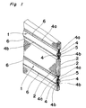
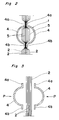
- FIGs. 1 to 3 there are illustrated principal portions of a heat exchanger of Embodiment 1 of the present invention. This embodiment corresponds to the aspects of the invention according to claims 1, 2 and 6.
- each heat transfer tube 1 consists of a pair of tube component members 4, 4 having a half cylindrical configuration, and having at their respective circumferential ends, joining flanges 4a, 4b extending along the axis of the heat transfer tube which act as joint portions.
- Reference numeral 5 designates inner fins formed by parts of the mesh-form fins 2, 2 ... being within the heat transfer tube 1.
- a heat exchanger of such construction is manufactured in the following manner.
- a multiplicity of mesh-form fins 2, 2 ... are stacked together, and a pair of tube component members 4, 4 are pressed against the mesh-form fins 2, 2 ... at a predetermined location externally of the fins as arrows P indicate. Thereafter, the opposed joining flanges 4a, 4a, and 4b, 4b are joined together to form a heat transfer tube 1.
- a heat transfer tube 1 For the purpose of such joining operation, for example, laser welding or ultrasonic welding is advantageously employed.
- spacing means e.
- spacer for keeping the mesh-form fins 2, 2 ... spaced apart may be used.
- the spacing means is removed after the heat exchanger has been manufactured.
- Reference numeral 6 in Fig. 1 designates laser weld or ultrasonic weld spots.
- assembling together of heat transfer tubes 1, 1 ... and mesh-form fins 2, 2 ... can be accomplished by a very simple process such that the opposed joining flanges 4a, 4a and 4b, 4b of a pair of tube component members 4, 4 are pressed against a multiplicity of mesh-form fins stacked together externally thereof, being thereby joined together.
- This provides for remarkable improvement in working efficiency during the process of making a heat exchanger.
- the fact that parts of the mesh-form fins 2, 2 ... are retained within the heat transfer tubes 1, 1 ... to form inner fins 5, 5 ... permits direct contact between the fluid (e. g., refrigerant) flowing in the heat transfer tubes 1, 1 ... and parts of the mesh-form fins 2, 2 ... (i. e., inner fins 5, 5 ...), resulting in improvement in the heat transfer performance.
- the fluid e. g., refrigerant
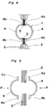
- FIGs. 4 and 5 there are illustrated principal portions of a heat exchanger of Embodiment 2 of the present invention. This embodiment corresponds to the aspects of the invention as defined in claims 1, 3 and 6.
- portions of the mesh-form fins 2, 2 ... to be located within each heat transfer tube 1 are cut off except portions against which opposed joining flanges 4a, 4a and 4b, 4b of tube component members 4, 4 are pressed, and portions 5 projecting therefrom slightly into the heat transfer tube 1 in a flared fashion.
- inner fins consist of short portions 5 projecting flaredly from the joint portions into the heat transfer tube 1. Therefore, the flow resistance of the fluid (e. g., refrigerant) flowing in the heat transfer tube 1 can be greatly reduced, and mesh-form fins 2, 2 can be prevented from slipping out of the joint portions.
- Other structural and functional features and effects of the embodiment are same as those of Embodiment 1.
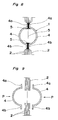
- FIGs. 6 and 7 there are illustrated principal portions of a heat exchanger of Embodiment 3 of the present invention. This embodiment corresponds to the aspects of the invention as defined in claims 1, 4 and 6.
- portions of mesh-form fins 2, 2 ... to be located within the heat transfer tube 1 are cut off except outermost mesh-form fins 2, 2. That is, the outermost mesh-form fins 2, 2 remain as they are, and the other mesh-form fins 2, 2 ... within the heat transfer tube 1 are cut off except portions against which opposed joining flanges 4a, 4a and 4b, 4b of tube component members 4, 4 are pressed, and portions 5 projecting flaredly therefrom.
- the flow resistance of the fluid (e. g., refrigerant) flowing in the heat transfer tube 1 can be greatly reduced.
- Other structural and functional features and effects of the embodiment are same as those of Embodiments 1 and 2.
- FIGs. 8 and 9 there are illustrated principal portions of a heat exchanger of Embodiment 4 of the present invention. This embodiment corresponds to the aspects of the invention as defined in claims 1, 5 and 6.
- portions of mesh-form fins 2, 2 ... to be located within the heat transfer tube 1 are cut off except portions against which opposed joining flanges 4a, 4a and 4b, 4b of tube component members 4, 4 are pressed, portions 5 projecting a short distance therefrom in a flared fashion and a mesh-form fin 5 positioned in the middle of the heat transfer tube 1.
- the flow resistance of the fluid (e. g., refrigerant) flowing in the heat transfer tube 1 can be greatly reduced.
- Other structural and functional features and effects of the embodiment are same as those of Embodiments 1 and 2.
- joining flanges are used as joint portions; alternatively, faucet joints or the like may be used.
- the mesh-fin type heat exchangers of the present invention are applicable for use in air conditioners, refrigerators, and the like.
Landscapes
- Engineering & Computer Science (AREA)
- Physics & Mathematics (AREA)
- Thermal Sciences (AREA)
- Mechanical Engineering (AREA)
- General Engineering & Computer Science (AREA)
- Geometry (AREA)
- Heat-Exchange Devices With Radiators And Conduit Assemblies (AREA)
Applications Claiming Priority (3)
| Application Number | Priority Date | Filing Date | Title |
|---|---|---|---|
| JP4177030A JPH0618186A (ja) | 1992-07-03 | 1992-07-03 | 熱交換器およびその製造方法 |
| JP177030/92 | 1992-07-03 | ||
| PCT/JP1993/000899 WO1994001731A1 (fr) | 1992-07-03 | 1993-06-30 | Echangeur thermique a ailettes maillees et son procede de production |
Publications (3)
| Publication Number | Publication Date |
|---|---|
| EP0601209A1 true EP0601209A1 (de) | 1994-06-15 |
| EP0601209A4 EP0601209A4 (de) | 1994-11-30 |
| EP0601209B1 EP0601209B1 (de) | 1997-06-11 |
Family
ID=16023923
Family Applications (1)
| Application Number | Title | Priority Date | Filing Date |
|---|---|---|---|
| EP93914936A Expired - Lifetime EP0601209B1 (de) | 1992-07-03 | 1993-06-30 | Wärmetauscher mit maschigen kühlrippen sowie verfahren zu dessen herstellung |
Country Status (5)
| Country | Link |
|---|---|
| US (1) | US5396949A (de) |
| EP (1) | EP0601209B1 (de) |
| JP (1) | JPH0618186A (de) |
| DE (1) | DE69311510T2 (de) |
| WO (1) | WO1994001731A1 (de) |
Families Citing this family (2)
| Publication number | Priority date | Publication date | Assignee | Title |
|---|---|---|---|---|
| ES2599877T3 (es) * | 2006-11-09 | 2017-02-03 | Liebherr-Hausgeräte Ochsenhausen GmbH | Aparato refrigerador y/o congelador |
| US8506242B2 (en) | 2010-05-04 | 2013-08-13 | Brayton Energy Canada, Inc. | Method of making a heat exchange component using wire mesh screens |
Family Cites Families (18)
| Publication number | Priority date | Publication date | Assignee | Title |
|---|---|---|---|---|
| DE276815C (de) * | ||||
| CA643979A (en) * | 1962-07-03 | Bundy Tubing Company | Heat transferring tube structure | |
| US2112743A (en) * | 1933-08-15 | 1938-03-29 | Gen Electric | Heat transmitting element |
| US2107031A (en) * | 1936-04-29 | 1938-02-01 | Gordon M Evans | Heat transferring tube structure |
| GB619307A (en) * | 1946-12-02 | 1949-03-08 | Heat Exchangers Ltd | Improvements relating to tubes for effecting the exchange of heat between fluids |
| CH398657A (de) * | 1962-05-11 | 1966-03-15 | Sulzer Ag | Rohr für Wärmeübertrager |
| US3409075A (en) * | 1965-08-20 | 1968-11-05 | Union Carbide Corp | Matrix heat exchange cores |
| NL6514628A (de) * | 1965-11-11 | 1967-05-12 | ||
| US3460613A (en) * | 1967-04-21 | 1969-08-12 | Peerless Of America | Heat exchangers |
| DE1551472A1 (de) * | 1967-04-28 | 1970-08-20 | Emil Langeheine | Waermeaustauscher mit ring- oder spiralfoermig gebogenen Rohrelementen |
| US4071935A (en) * | 1975-08-07 | 1978-02-07 | Stainless Equipment Company | Method of making heat exchanger |
| JPS52108546A (en) * | 1976-03-08 | 1977-09-12 | Toyo Rajieetaa Kk | Heat exchanger and method of producing same |
| SE7808367L (sv) * | 1978-08-03 | 1980-02-04 | Ostbo John D B | Anordning vid vermevexlare |
| JPS60111880U (ja) * | 1983-12-30 | 1985-07-29 | 東洋ラジエーター株式会社 | 熱交換器の放熱体 |
| JPS61192185U (de) * | 1985-05-21 | 1986-11-29 | ||
| JPS6349190U (de) * | 1986-09-18 | 1988-04-02 | ||
| JPS63189794A (ja) * | 1987-02-03 | 1988-08-05 | Matsushita Refrig Co | 熱交換器 |
| FR2668250B1 (fr) * | 1990-10-22 | 1997-01-10 | Inst Francais Du Petrole | Echangeur de chaleur a tubes relies par des plaques de metal deploye. |
-
1992
- 1992-07-03 JP JP4177030A patent/JPH0618186A/ja active Pending
-
1993
- 1993-06-30 DE DE69311510T patent/DE69311510T2/de not_active Expired - Fee Related
- 1993-06-30 WO PCT/JP1993/000899 patent/WO1994001731A1/ja not_active Ceased
- 1993-06-30 US US08/204,198 patent/US5396949A/en not_active Expired - Fee Related
- 1993-06-30 EP EP93914936A patent/EP0601209B1/de not_active Expired - Lifetime
Also Published As
| Publication number | Publication date |
|---|---|
| JPH0618186A (ja) | 1994-01-25 |
| DE69311510T2 (de) | 1997-11-06 |
| WO1994001731A1 (fr) | 1994-01-20 |
| US5396949A (en) | 1995-03-14 |
| EP0601209A4 (de) | 1994-11-30 |
| EP0601209B1 (de) | 1997-06-11 |
| DE69311510D1 (de) | 1997-07-17 |
Similar Documents
| Publication | Publication Date | Title |
|---|---|---|
| US5538077A (en) | In tank oil cooler | |
| US4917180A (en) | Heat exchanger with laminated header and tank and method of manufacture | |
| US4688311A (en) | Method of making a heat exchanger | |
| US4932469A (en) | Automotive condenser | |
| JPH074885A (ja) | 熱交換器 | |
| US5052480A (en) | Pipe for coolant condenser | |
| US5369883A (en) | Method for making an in tank oil cooler | |
| US5214847A (en) | Method for manufacturing a heat exchanger | |
| JPH06159981A (ja) | 熱交換器 | |
| JPH07318289A (ja) | 熱交換器 | |
| CA1313182C (en) | In tank oil cooler | |
| KR20010101414A (ko) | 코일열교환기 및 이를 제조하는 방법 | |
| US5396949A (en) | Mesh fin type heat exchanger and method of making the same | |
| EP0612396B1 (de) | Ölkühler in einem tank | |
| JP4043079B2 (ja) | 熱交換器のヘッダパイプ | |
| JPH0640667U (ja) | 熱交換器 | |
| JP2701939B2 (ja) | アルミニウム製熱交換器の製造方法 | |
| JPS64639B2 (de) | ||
| JPH02290666A (ja) | 熱交換器の製造方法 | |
| JPH01142393A (ja) | 熱交換器 | |
| JPH0711332Y2 (ja) | 熱交換器 | |
| JPH01217195A (ja) | 熱交換器 | |
| JP2000061623A (ja) | 熱交換器の製造方法 | |
| JPH0325297A (ja) | 熱交換器 | |
| JPH01174898A (ja) | 熱交換器用チューブ |
Legal Events
| Date | Code | Title | Description |
|---|---|---|---|
| PUAI | Public reference made under article 153(3) epc to a published international application that has entered the european phase |
Free format text: ORIGINAL CODE: 0009012 |
|
| AK | Designated contracting states |
Kind code of ref document: A1 Designated state(s): BE DE FR GB IT |
|
| 17P | Request for examination filed |
Effective date: 19940310 |
|
| A4 | Supplementary search report drawn up and despatched | ||
| AK | Designated contracting states |
Kind code of ref document: A4 Designated state(s): BE DE FR GB IT |
|
| 17Q | First examination report despatched |
Effective date: 19950307 |
|
| GRAG | Despatch of communication of intention to grant |
Free format text: ORIGINAL CODE: EPIDOS AGRA |
|
| GRAH | Despatch of communication of intention to grant a patent |
Free format text: ORIGINAL CODE: EPIDOS IGRA |
|
| GRAH | Despatch of communication of intention to grant a patent |
Free format text: ORIGINAL CODE: EPIDOS IGRA |
|
| GRAA | (expected) grant |
Free format text: ORIGINAL CODE: 0009210 |
|
| AK | Designated contracting states |
Kind code of ref document: B1 Designated state(s): BE DE FR GB IT |
|
| REF | Corresponds to: |
Ref document number: 69311510 Country of ref document: DE Date of ref document: 19970717 |
|
| ET | Fr: translation filed | ||
| PLBE | No opposition filed within time limit |
Free format text: ORIGINAL CODE: 0009261 |
|
| STAA | Information on the status of an ep patent application or granted ep patent |
Free format text: STATUS: NO OPPOSITION FILED WITHIN TIME LIMIT |
|
| 26N | No opposition filed | ||
| REG | Reference to a national code |
Ref country code: GB Ref legal event code: IF02 |
|
| PGFP | Annual fee paid to national office [announced via postgrant information from national office to epo] |
Ref country code: FR Payment date: 20020610 Year of fee payment: 10 |
|
| PGFP | Annual fee paid to national office [announced via postgrant information from national office to epo] |
Ref country code: GB Payment date: 20020626 Year of fee payment: 10 |
|
| PGFP | Annual fee paid to national office [announced via postgrant information from national office to epo] |
Ref country code: DE Payment date: 20020702 Year of fee payment: 10 |
|
| PGFP | Annual fee paid to national office [announced via postgrant information from national office to epo] |
Ref country code: BE Payment date: 20020829 Year of fee payment: 10 |
|
| PG25 | Lapsed in a contracting state [announced via postgrant information from national office to epo] |
Ref country code: GB Free format text: LAPSE BECAUSE OF NON-PAYMENT OF DUE FEES Effective date: 20030630 Ref country code: BE Free format text: LAPSE BECAUSE OF NON-PAYMENT OF DUE FEES Effective date: 20030630 |
|
| BERE | Be: lapsed |
Owner name: *DAIKIN INDUSTRIES LTD Effective date: 20030630 |
|
| PG25 | Lapsed in a contracting state [announced via postgrant information from national office to epo] |
Ref country code: DE Free format text: LAPSE BECAUSE OF NON-PAYMENT OF DUE FEES Effective date: 20040101 |
|
| GBPC | Gb: european patent ceased through non-payment of renewal fee |
Effective date: 20030630 |
|
| PG25 | Lapsed in a contracting state [announced via postgrant information from national office to epo] |
Ref country code: FR Free format text: LAPSE BECAUSE OF NON-PAYMENT OF DUE FEES Effective date: 20040227 |
|
| REG | Reference to a national code |
Ref country code: FR Ref legal event code: ST |
|
| PG25 | Lapsed in a contracting state [announced via postgrant information from national office to epo] |
Ref country code: IT Free format text: LAPSE BECAUSE OF NON-PAYMENT OF DUE FEES Effective date: 20050630 |