EP0601230A1 - Vereinfachter, vollautomatischer Regenschirm - Google Patents
Vereinfachter, vollautomatischer Regenschirm Download PDFInfo
- Publication number
- EP0601230A1 EP0601230A1 EP92120933A EP92120933A EP0601230A1 EP 0601230 A1 EP0601230 A1 EP 0601230A1 EP 92120933 A EP92120933 A EP 92120933A EP 92120933 A EP92120933 A EP 92120933A EP 0601230 A1 EP0601230 A1 EP 0601230A1
- Authority
- EP
- European Patent Office
- Prior art keywords
- umbrella
- ring
- inner tube
- fully automatic
- pawl
- Prior art date
- Legal status (The legal status is an assumption and is not a legal conclusion. Google has not performed a legal analysis and makes no representation as to the accuracy of the status listed.)
- Withdrawn
Links
- 244000182067 Fraxinus ornus Species 0.000 claims 1
- 238000010276 construction Methods 0.000 description 3
- 230000004048 modification Effects 0.000 description 1
- 238000012986 modification Methods 0.000 description 1
- 210000003813 thumb Anatomy 0.000 description 1
Images


Classifications
-
- A—HUMAN NECESSITIES
- A45—HAND OR TRAVELLING ARTICLES
- A45B—WALKING STICKS; UMBRELLAS; LADIES' OR LIKE FANS
- A45B25/00—Details of umbrellas
- A45B25/14—Devices for opening and for closing umbrellas
- A45B25/143—Devices for opening and for closing umbrellas automatic
Definitions
- This application relates to a fully automatic umbrella, more particularly to an umbrella having significantly simplified construction.
- a fully automatic umbrella which comprises a shank consisting of an inner and an outer tubes capable of relative sliding movement with respect to each other, in which said inner tube having a middle ring at upper section and an extension outreached over said middle ring while said outer tube having a lower ring at upper ends, both tubes being provided with respective upper and lower aligned apertures; an umbrella opening spring telescopically received within said extension of said inner tube; a cylinder mounted around said extension for relative sliding movement therewith and provided with an upper ring at lower end; an umbrella closing spring telescopically mounted around said inner tube in the limit between said middle ring and the top end of said outer tube; a locking mechanism consisting of an upper and a lower pawls to be respectively locked into said upper and lower aligned apertures for restricting said umbrella opening and closing springs at a locked state, respectively; a canopy structure connected with said upper, middle and lower rings correspondingly; a wire interconnected between said upper pawl and said lower ring for pushing and pulling
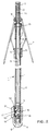
- Fig.1 shows that the present invention mainly comprises a shank 1, an umbrella opening spring 2, a cylinder 3, an umbrella closing spring 4, an upper pawl 5, a lower pawl 6, a canopy structure 7, a wire 8 and a handle 9.
- the shank 1 consists of an inner tube 11 and an outer tube 12 capable of relative sliding movement with respect to each other.
- Said inner tube 11 is provided with a fixed middle ring 13 at upper section.
- an extension 14 is outreached over said middle ring 13.
- Said outer tube 12 is provided with a movable lower ring 15 which is slidable in relation to said outer tube 12.
- Both inner and outer tubes 11, 12 are provided with upper apertures 16, 17 and lower apertures 18, 19, respectivley. In the preparative state as shown in Fig.2, namely, when said inner tube 11 is flushed with said outer tube 12 at both lower ends, said upper apertures 16 and 17 as well as said lower apertures 18 and 19 are aligned to each other respectively.
- the umbrella opening spring 2 is telescopically received within said extension 14 of said inner tube 11.
- Said extension 14 is housed within a cylinder 3.
- Said cylinder 3 is slidable in relation to said extension 14 in cooperation with the telexcopic action of said opening spring 2.
- the cylinder 3 is provided with a fixed upper ring 31 at lower end.
- the umbrella closing spring 4 is telescopically mounted in the limit between said middle ring 13 and the top end of said outer tube 12. Said outer tube 12 is slidable in relation to said inner tube 11 in cooperation with the telescopic action of said closing spring 4.
- Said upper and lower pawls 5,6 constitute a locking mechanism.
- Said lowerpawl 6 is resiliently secured at lower end of said inner tube 11 by means of a hair spring 61, while said upper pawl 5 is resiliently secured in a housing 52 similarly by means of a hair spring 51 in which said housing 52 is, in turns, slidably movable within said inner tube 11.
- said housing 52 is provided with a slit for allowing the hook portion of said upper pawl 5 protruding out therethrough.
- the wire 8 is interconnected between said upper pawl 5 and said lower ring 15.
- the outer tube 12 has a longitudinal slot 20 below said lower ring 15 while the inner tube 11 has also a longitudinal slot 21 at corresponding intermediate section.
- the wire 8 is deflected at upper end to pass through out of the aligned slots 20,21 and then bent returned to engage into said lower ring 15. This wire 8 is so rigid that capable of pushing and pulling said upper pawl 5.
- each constituting rib is at one end pivotably connected to said upper, middle and lower rings 31,13 and 15 correspondingly.
- the handle 9 is mounted at lower end of the shank 1.
- an actuating member 91 is provided with two protrusions, namely, the umbrella opening and closing actuating portions 92 and 93, respectively, directing to said upper and lower apertures 17,19 of said outer tube 12.
- said lower ring 15 is optionally provided with a locking means 22 to be locked into the correspondingly aligned lock holes 23 and 24 in said inner and outer tubes 11 and 12, respectively, so as to support said lower ring 15 more stable and thereby to prevent said canopy structure from slipping off by accident.
- a preparative action should be taken by the user, for example, holding the handle 9 with one hand and putting the end of the cylinder 3 against any surface of the ground, a wall or another hand of himself.
- said outer tube 12 will be slidably moved in relation to said inner tube 11 to cause said umbrella closing spring 4 compressed. Since in the closing state of the umbrella, the umbrella opening spring 2 is kept under the compressed state, so that in the action of preparative operation only the umbrella closing spring 4 is going to be compressed which is easily accomplished by a slight force.
- the handle 9 brought by said outer tube 12 is moved upwards in relation to said inner tube 11 to push the locking means 22 of said lower ring 15 out of the corresponding lock holes 23,23, until the upper and lower apertures 17 and 19 thereof are aligned with the upper and lower apertures 18 and 20, respectively.
- the upper pawl 5 is pushed downwards by the wire 8 to lock into the aligned apertures 16 and 17 to restrict said umbrella opening spring 2 at compressed and locked state while the lower pawl 6 brought by said inner tube 11 is simultaneously moved downwards in relation to said outer tube 12 until locked into the alighed apertures 18 and 19 to restrict said umbrella closing spring 4 at compressed and locked state, as illustrated in Fig. 2.
- the umbrella can be opened any time.
- said thumb for example, of the hand that holds the handle 9 presses upper side of the actuating mechanism 91
- said upper pawl 5 is thus pressed down by the umbrella opening actuating portion 92 out of the aligned apertures 16 and 17, then the locked state of said umbrella opening spring 2 is released.
- said umbrella opening spring 2 is expanded by its own accumulated energy when compressed, then the cylinder 2 is moved upwards in relation to the extension 14 of said inner tube 11 so as to open the canopy structure 7.
- the lower ring 15 is moved upwards to the top end of the outer tube 12, the locking member 22 is locked into the aligned lock holes 23,24 and the upper pawl 5 is pulled upwards by the wire 8.
- the lower pawl 6 is kept under locked state, as illustrated in Fig.3.
- the arrangement and construction of the automatic umbrella according to the present invention are significantly simplified, yet the structure is still sufficient strong and stable. Furthermore, the operation is easy and positive, and the production cost is greatly reduced.
Landscapes
- Walking Sticks, Umbrellas, And Fans (AREA)
Priority Applications (3)
| Application Number | Priority Date | Filing Date | Title |
|---|---|---|---|
| AU28460/92A AU2846092A (en) | 1992-11-18 | 1992-11-18 | A simplified fully automatic umbrella |
| CA002083247A CA2083247A1 (en) | 1992-11-18 | 1992-11-18 | Simplified fully automatic umbrella |
| EP92120933A EP0601230A1 (de) | 1992-11-18 | 1992-12-09 | Vereinfachter, vollautomatischer Regenschirm |
Applications Claiming Priority (3)
| Application Number | Priority Date | Filing Date | Title |
|---|---|---|---|
| AU28460/92A AU2846092A (en) | 1992-11-18 | 1992-11-18 | A simplified fully automatic umbrella |
| CA002083247A CA2083247A1 (en) | 1992-11-18 | 1992-11-18 | Simplified fully automatic umbrella |
| EP92120933A EP0601230A1 (de) | 1992-11-18 | 1992-12-09 | Vereinfachter, vollautomatischer Regenschirm |
Publications (1)
| Publication Number | Publication Date |
|---|---|
| EP0601230A1 true EP0601230A1 (de) | 1994-06-15 |
Family
ID=27153171
Family Applications (1)
| Application Number | Title | Priority Date | Filing Date |
|---|---|---|---|
| EP92120933A Withdrawn EP0601230A1 (de) | 1992-11-18 | 1992-12-09 | Vereinfachter, vollautomatischer Regenschirm |
Country Status (3)
| Country | Link |
|---|---|
| EP (1) | EP0601230A1 (de) |
| AU (1) | AU2846092A (de) |
| CA (1) | CA2083247A1 (de) |
Citations (7)
| Publication number | Priority date | Publication date | Assignee | Title |
|---|---|---|---|---|
| FR2094251A5 (de) * | 1970-06-15 | 1972-02-04 | Tissmetal Lionel Dupont | |
| EP0151847A1 (de) * | 1984-02-08 | 1985-08-21 | San-Tong Day | Völlig automatischer Schirm |
| EP0291589A1 (de) * | 1987-05-18 | 1988-11-23 | San-Tong Day | Selbstöffnender und selbstschliessender automatischer Schirm mit einer einzigen Drucktaste |
| DE3812613A1 (de) * | 1988-04-15 | 1989-10-26 | Su Tseng | Schirm, insbesondere regenschirm |
| US5088512A (en) * | 1991-07-26 | 1992-02-18 | Sheng-Tong Day | Lightly operable fully automatic umbrella |
| US5144969A (en) * | 1991-09-12 | 1992-09-08 | Day Sheng-Tong | Fully automatic collapsible umbrella |
| DE9213055U1 (de) * | 1992-09-28 | 1992-12-10 | Chu, Chin-Tang | Zweiknopf-Sicherheitsschirm |
-
1992
- 1992-11-18 CA CA002083247A patent/CA2083247A1/en not_active Abandoned
- 1992-11-18 AU AU28460/92A patent/AU2846092A/en not_active Abandoned
- 1992-12-09 EP EP92120933A patent/EP0601230A1/de not_active Withdrawn
Patent Citations (7)
| Publication number | Priority date | Publication date | Assignee | Title |
|---|---|---|---|---|
| FR2094251A5 (de) * | 1970-06-15 | 1972-02-04 | Tissmetal Lionel Dupont | |
| EP0151847A1 (de) * | 1984-02-08 | 1985-08-21 | San-Tong Day | Völlig automatischer Schirm |
| EP0291589A1 (de) * | 1987-05-18 | 1988-11-23 | San-Tong Day | Selbstöffnender und selbstschliessender automatischer Schirm mit einer einzigen Drucktaste |
| DE3812613A1 (de) * | 1988-04-15 | 1989-10-26 | Su Tseng | Schirm, insbesondere regenschirm |
| US5088512A (en) * | 1991-07-26 | 1992-02-18 | Sheng-Tong Day | Lightly operable fully automatic umbrella |
| US5144969A (en) * | 1991-09-12 | 1992-09-08 | Day Sheng-Tong | Fully automatic collapsible umbrella |
| DE9213055U1 (de) * | 1992-09-28 | 1992-12-10 | Chu, Chin-Tang | Zweiknopf-Sicherheitsschirm |
Also Published As
| Publication number | Publication date |
|---|---|
| AU2846092A (en) | 1994-06-02 |
| CA2083247A1 (en) | 1994-05-19 |
Similar Documents
| Publication | Publication Date | Title |
|---|---|---|
| EP0156045B1 (de) | Völlig automatischer Schirm mit einem einzigen Druckknopf | |
| US4823821A (en) | Automatic single push button type umbrella | |
| US5174319A (en) | Longer effective automatic umbrella | |
| US4548222A (en) | Full-automatic umbrella | |
| EP0425071B1 (de) | Automatischer Schirm | |
| CA2047974C (en) | Lightly operable fully automatic umbrella | |
| CA2129609C (en) | Folding collapsible frame assembly for an automatic folding umbrella | |
| US4936332A (en) | Simply-constructed automatic umbrella for preventing false operation | |
| AU658350B1 (en) | Simplified fully automatic umbrella | |
| EP0151847B1 (de) | Völlig automatischer Schirm | |
| US5060684A (en) | Automatic umbrella foldably retained by tip cap | |
| US5161562A (en) | Umbrella with simplified automatic closing mechanism | |
| EP0498986A2 (de) | Automatischer Schirm mit einem in gerader Linie zu bewegenden Druckknopf zum Öffnen und Schliessen des Schirmes | |
| US5247955A (en) | Ergonomically operating automatic umbrella | |
| CA2083247A1 (en) | Simplified fully automatic umbrella | |
| JP2945389B1 (ja) | 多段折畳み式自動開閉傘 | |
| EP0518814A2 (de) | Selbstöffnender und selbstschliessender Schirm | |
| JPH06205703A (ja) | 完全自動傘 | |
| JP2587891B2 (ja) | 操作性の良い自動開閉式洋傘 | |
| JP2637338B2 (ja) | 多重折畳式自動開閉洋傘 | |
| CN2045587U (zh) | 单钮操作式全自动折合伞 | |
| JP2511622Y2 (ja) | 洋傘の自動開閉機構 | |
| EP0573689A1 (de) | Automatischer Regenschirm mit verlängertem Gebrauch | |
| CA1218912A (en) | Full-automatic umbrella | |
| EP0979623B1 (de) | Automatisch öffnender Schirm |
Legal Events
| Date | Code | Title | Description |
|---|---|---|---|
| PUAI | Public reference made under article 153(3) epc to a published international application that has entered the european phase |
Free format text: ORIGINAL CODE: 0009012 |
|
| AK | Designated contracting states |
Kind code of ref document: A1 Designated state(s): AT BE CH DE DK ES FR GB GR IE IT LI LU MC NL PT SE |
|
| STAA | Information on the status of an ep patent application or granted ep patent |
Free format text: STATUS: THE APPLICATION IS DEEMED TO BE WITHDRAWN |
|
| 18D | Application deemed to be withdrawn |
Effective date: 19941216 |