EP0601252B1 - Herdrolle mit unterdrückter thermischer Balligkeit - Google Patents
Herdrolle mit unterdrückter thermischer Balligkeit Download PDFInfo
- Publication number
- EP0601252B1 EP0601252B1 EP92403373A EP92403373A EP0601252B1 EP 0601252 B1 EP0601252 B1 EP 0601252B1 EP 92403373 A EP92403373 A EP 92403373A EP 92403373 A EP92403373 A EP 92403373A EP 0601252 B1 EP0601252 B1 EP 0601252B1
- Authority
- EP
- European Patent Office
- Prior art keywords
- sleeve
- roller
- hearth
- inner sleeve
- hearth roller
- Prior art date
- Legal status (The legal status is an assumption and is not a legal conclusion. Google has not performed a legal analysis and makes no representation as to the accuracy of the status listed.)
- Expired - Lifetime
Links
Images

Classifications
-
- C—CHEMISTRY; METALLURGY
- C21—METALLURGY OF IRON
- C21D—MODIFYING THE PHYSICAL STRUCTURE OF FERROUS METALS; GENERAL DEVICES FOR HEAT TREATMENT OF FERROUS OR NON-FERROUS METALS OR ALLOYS; MAKING METAL MALLEABLE, e.g. BY DECARBURISATION OR TEMPERING
- C21D9/00—Heat treatment, e.g. annealing, hardening, quenching or tempering, adapted for particular articles; Furnaces therefor
- C21D9/52—Heat treatment, e.g. annealing, hardening, quenching or tempering, adapted for particular articles; Furnaces therefor for wires; for strips ; for rods of unlimited length
- C21D9/54—Furnaces for treating strips or wire
- C21D9/56—Continuous furnaces for strip or wire
- C21D9/562—Details
- C21D9/563—Rolls; Drums; Roll arrangements
Definitions
- the present invention relates to hearth rollers for conveying metal strips, and more particularly to hearth rollers having a suppressed heat crown in an area where a metal strip contacts the roller so that it is possible to convey metal strips at a high temperature in a stable manner.
- hearth rollers In many processing lines such as a continuous heat treating furnace (e.g., continuous annealing furnace) many hearth rollers have been employed to convey metal strips (sometimes referred to merely as "strip" hereunder). In such conventional hearth rollers, a predetermined initial crown is provided in order to convey strips in a stable manner.
- hearth rollers provided within the furnace must carry metal strips having a variety of temperatures, widths, and thicknesses, and a heat crown is inevitably generated by such factors so that the initial roll crown of the roller cannot be kept to the predetermined one.
- Hearth rollers which can adjust the crown mechanically.
- a tapered surface 10 provided within the hearth roller 9 engages with an adjusting member 12.
- the position of the adjusting member 12 is movable along a longitudinal axis of the roller by means of an adjusting means 14 provided outside the roller.
- the roll crown can be adjusted by controlling the degree of inclination of the tapered surface 10 which engages with the adjusting member 12 so that a sleeve 16 can be deformed.
- a variation of the roll crown is caused by the occurrence of a heat crown, which is then derived from a variation in temperatures of the strip in the widthwise and longitudinal directions.
- a heat crown which is then derived from a variation in temperatures of the strip in the widthwise and longitudinal directions.
- roll crown variations can be mechanically offset by the deformation of the sleeve caused by the movement of the tapered surface, and a given level of crown can be maintained.
- Japanese Patent Application Unexamined Specification No. 63-65016/1988 discloses another hearth roller which can prevent a heat crown by making the thermal distribution uniform throughout the roller.
- Such hearth rollers as is shown in Figure 12, contain a molten metal 20 as a thermal medium within the roller 22 so that the temperature deviation in the axial direction of the roller barrel 24 can be diminished to suppress the occurrence of heat crown itself.
- the hearth roller shown in Figure 11 requires a control system which can estimate or measure a change in heat crown whenever it occurs so as to maintain a predetermined roll crown.
- a control system adds to costs.
- a hearth roller shown in Figure 12 essentially utilizes the thermal content of the thermal medium. Since the thermal content is equal to the product of the specific heat by the mass, it is more advantageous to use a molten metal than a molten salt in order to make the temperatures of the roller uniform in the widthwise direction. This is because metals have a larger mass, i.e., a larger density than molten salts. However, when a metal is used, then the mass distribution of the roller is not uniform, and the roller is subjected to a centrifugal force, causing vibration. In order to prevent the roller from vibrating it is necessary to further employ additional equipment such as bearings. This also adds to costs. In the case of a molten salt, its effectiveness at producing uniformity of the roller temperature is degraded to some extent, although the costs are reduced, in comparison with the case in which a molten metal is used.
- An object of the present invention is to provide hearth rollers which can avoid such problems of the prior art, and which does not require any specific control system, but which can maintain a predetermined initial crown in order to stably convey metal strips regardless of changes in carrying conditions of the metal strips.
- Another object of the present invention is to provide hearth rollers with a suppressed heat crown in which a buffer effect is strengthened by increasing the heat transfer capability of the roller in order to offset changes in the temperature distribution in the widthwise direction which occur when metal strips having different widths are conveyed continuously.
- Still another object of the present invention is to provide less expensive hearth rollers of a simple structure which are corrosion resistant and strong enough to withstand high temperature conditions at 1000°C such as experienced when strips are conveyed on the hearth rollers.
- a heat crown is mainly derived from the occurrence of a temperature gradient in the barrel of a hearth roller, i.e., in the hearth roller body, and that such a heat crown can be eliminated by achieving a rapid heat transfer through the body of a hearth roller to diminish such a temperature gradient, while ensuring high temperature strength and corrosion resistance.
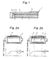
- FIG. 1 is a schematic sectional view of a portion of a hearth roller of the present invention.
- the hearth roller 1 comprises a hearth roller barrel (outer sleeve) 2, a metallic sleeve (inner sleeve) 3, and an innermost sleeve 4.
- the metallic sleeve 3 has substantially the same linear expansion coefficient as that of the outer sleeve but exhibits further improved thermal conductivity, and is fitted to the inner surface of the outer sleeve by means such as shrink fit or duplex casting.
- the innermost sleeve 4 is fitted to the inner surface of the metallic sleeve 3 by means such as thermal insertion, i. e., shrink fit.
- a metal strip 6 is conveyed while being carried on the outer sleeve 2.
- the ends of the inner sleeve 3 in the axial direction are positioned inwardly and separated from each of the ends of the outer sleeve 2 and are sealed with a metal member of a weld metal or a ring made of the same metal as the innermost sleeve 4. Namely, the inner sleeve 3 is totally isolated from the surrounding atmosphere.
- the inner sleeve 3 is made of a single piece, but it may be of a multi-piece type divided into pieces in the axial direction.
- the axial end of the inner sleeve 3 is positioned inwardly from the axial end of the outer sleeve 2 which constitutes a hearth roller barrel.
- the distance d between the two ends is not restricted to a specific one, so long as thermal streams are interrupted thoroughly between them. Usually the distance "d" is about 1 mm.
- the outer sleeve 2 and the innermost sleeve 4 may be made of the same or different metals. Usually it is desirable that these sleeves be made of same metal. On the other hand, the inner sleeve 3 is made of a metal different from that of these sleeves and exhibits improved thermal conductivity.
- a hearth roller is made of a stainless steel.
- the sleeve 2 is made of a stainless steel.
- the inner sleeve be made of copper.
- the innermost sleeve 4 and the ring 5 are also preferably made of stainless steel.
- the outer sleeve 2, the innermost sleeve 4 and the ring 5 are made of a heat resistant steel, and the inner sleeve 3 is made of aluminum or silver.
- the outer sleeve 2, the innermost sleeve 4 and the ring 5 be made of a metal which exhibits improved heat resistance and that the inner sleeve 3 be made of a metal having improved thermal conductivity.
- the service temperature thereof is up to about 500°C.
- the corrosion resistance and strength of a copper inner sleeve are adequate.
- the hearth rollers are used at a temperature around 1000°C, which is near to the melting point of copper, the strength of copper is decreased markedly and oxidation of copper takes place.
- the inner sleeve be sealed in an inert atmosphere or vacuum, but the service life for a hearth roller comprising an outer sleeve the thickness of which has been reduced for the purposes of energy saving and economy is markedly reduced.
- the inner sleeve 3 made of copper is fitted into the outer sleeve 2 with the axial ends of the inner sleeve 3 being separated from those of the outer sleeve 2.
- the inner sleeve 3 is also isolated from the surrounding atmosphere by the innermost sleeve 4 and the ring 5.
- the inner sleeve made of copper is sealed from the outside, even if the copper is melted down, the strength of the hearth roller can be ensured by the outer sleeve which is made of a heat resistant steel, e.g., stainless steel. Oxidation of the copper can also be prevented because the inner sleeve is sealed. It is desirable, in this case, too, to place the inner sleeve in an inert gas or vacuum atmosphere.
- the hearth roller with improved properties of corrosion resistance can be used at a temperature of about 1000°C.
- the thickness of the inner sleeve 3 is not restricted to a specific one, but it is preferable from the standpoint of improving heat conduction that the thickness of the inner sleeve 3 be larger than that of the outer sleeve 2. Usually the thickness of the inner sleeve is 10 - 30 mm.
- the total thickness of the outer sleeve 2 and the innermost sleeve 4 is about 15 - 30 mm, which is substantially the same as that for the outer sleeve of the conventional roller which was designed taking creep strength and the like into consideration.
- the linear expansion coefficients for each of the sleeves are substantially the same. The formation of thermal stress is suppressed even if the temperature of the roller or metal strip is varied, and fitting of all these sleeves can be maintained with prevention of a tensile thermal stress which might cause creeping and the like.
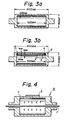
- Figures 3a and 3b show the shapes and dimensions (mm) of the hearth rollers used in this example.
- Figure 3a is a schematic sectional view of a conventional roller made of heat resistant stainless steel. This roller represents a comparative example.
- Figure 3b shows a hearth roller of the present invention.
- the inner sleeve 3 made of copper is fitted into the outer sleeve 2, i.e., the hearth roller barrel made of heat resistant stainless steel, and the innermost sleeve 4 made of heat resistant stainless steel is then fitted into the inner sleeve by shrink fit. Both ends of the inner sleeve 3 are sealed by fitting the ring 5 made of heat resistant stainless steel to the outer and innermost sleeves by welding.
- a steel strip used in this example was an annealed steel strip having a thickness of 0.15 mm and a width of 280 mm.
- a heat crown formed while conveying the metal strip was measured during the conveying process with a measuring device of the contact type.
- a model test simulating employment of the hearth roller of the present invention in a cooling zone of a continuous annealing furnace was carried out by conveying the strip in an atmosphere kept at 900°C on the hearth rollers.
- the strip was previously heated to a given temperature, e.g., 1000°C. This test will be indicated as "Model Test I" hereinafter.
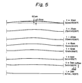
- Figure 5 is a graph of formation of heat crown with respect to the time elapses for the conventional hearth roller in Model Test I.
- the temperature of the strip at the inlet of the roller was about 1060°C, and the heat crown reached a stationary level after about 30 minutes.
- the heat crown was determined while conveying the strip on the hearth rollers and the heat crown determined was that on the stationary level.
- Figures 6 and 7 are graphs showing heat crown for the conventional hearth roller and for the hearth roller of the present invention in Model Test I.
- the CRS decreased from 62 micrometers to 16 micrometers, and the gradient of heat crown in the axial direction was smooth.
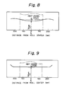
- Figures 8 and 9 are graphs showing the heat crown of the conventional hearth roller and the hearth roller of the present invention in Model Test II.
- the temperature of the surface of the hearth roller at the center in the axial direction was kept at about 980°C by adjusting the power of the heater 7.
- the CRS decreased from 33 micrometers to 2 micrometers.
- the heat crown could be reduced by about 74% in the cooling zone and about 94% in the heating zone, which are marked results.
- the gradient of heat crown in the axial direction was smooth, which is very advantageous from a practical viewpoint. Troubles in operation during conveying strips occur mainly when the width of strips is changed, particularly the width of strips being conveyed changed from narrow to broad. This is because there is a marked increase in the CRS. Thus, according to the present invention such troubles can be eliminated completely.
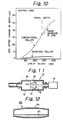
- Figure 10 is a graph showing what changes in the CRS occur immediately after the width of a strip is switched from the initial width of 280 mm to a smaller or larger one as indicated for the conventional hearth roller and for the hearth roller of the present invention in Model Test II.
- hearth roller comprising an inner sleeve made of copper and outer and innermost sleeves and a ring each made of a heat resistant stainless steel, the resulting hearth roller can withstand a temperature of 1000°C with improved corrosion resistance, so that the hearth roller can be used continuously at 1200°C for over 500 hours.
Landscapes
- Chemical & Material Sciences (AREA)
- Engineering & Computer Science (AREA)
- Physics & Mathematics (AREA)
- Thermal Sciences (AREA)
- Crystallography & Structural Chemistry (AREA)
- Mechanical Engineering (AREA)
- Materials Engineering (AREA)
- Metallurgy (AREA)
- Organic Chemistry (AREA)
- Heat Treatment Of Strip Materials And Filament Materials (AREA)
Claims (8)
- Herdrolle, umfassend eine äußere Büchse (2), die die Herdrollentrommel bildet, eine innere Büchse (3), die in der äußeren Büchse passend angeordnet ist, wobei die Enden der inneren Büchse (3) in Axialrichtung jeweils einwärts und getrennt von den Enden der äußeren Büchse angeordnet sind und die innere Büchse im wesentlichen den gleichen linearen Ausdehnungskoeffizienten wie die äußere Büchse (2) besitzt, jedoch eine verbesserte Wärmeleitfähigkeit aufweist, dadurch gekennzeichnet, dass die Herdrolle ferner eine innerste Büchse (4) umfaßt, die in der inneren Büchse passend angeordnet ist, wobei die Enden der inneren Büchse (3) in Axialrichtung durch ein Metall abgedichtet sind, und dass die Enden der innersten Büchse in Axialrichtung und das Dichtmetall jeweils einwärts und getrennt von den Enden der äußeren Büchse angeordnet sind.
- Herdrolle nach Anspruch 1, wobei die Passung der inneren Büchse (3) in der äußeren Büchse und der innersten Büchse in der inneren Büchse durch eine Schrumpfpassung ausgeführt ist.
- Herdrolle nach Anspruch 1, wobei die Passung der inneren Büchse (3) in der äußeren Büchse und der innersten Büchse in der inneren Büchse durch einen Duplexguß ausgeführt ist.
- Herdrolle nach einem der Ansprüche 1 bis 3, wobei die äußere Büchse und die innerste Büchse aus dem gleichen Metall bestehen.
- Herdrolle nach einem der Ansprüche 1 bis 4, wobei die Enden der inneren Büchse durch einen Ring (5) abgedichtet sind und der Ring und die innerste Büchse aus dem gleichen Metall bestehen.
- Herdrolle nach einem der Ansprüche 1 bis 5, wobei die innere Büchse aus Kupfer besteht und die äußere Büchse und die innerste Büchse aus einem wärmebeständigen rostfreien Stahl bestehen.
- Herdrolle nach einem der Ansprüche 1 bis 6, wobei die innere Büchse in einer Inertatmosphäre abgedichtet ist.
- Herdrolle nach einem der Ansprüche 1 bis 7, wobei die innere Büchse vom einstückigen Typ ist.
Priority Applications (3)
| Application Number | Priority Date | Filing Date | Title |
|---|---|---|---|
| JP3140344A JPH04365820A (ja) | 1991-06-12 | 1991-06-12 | 熱クラウン抑制ハースロール |
| DE1992625327 DE69225327T2 (de) | 1992-12-11 | 1992-12-11 | Herdrolle mit unterdrückter thermischer Balligkeit |
| EP92403373A EP0601252B1 (de) | 1991-06-12 | 1992-12-11 | Herdrolle mit unterdrückter thermischer Balligkeit |
Applications Claiming Priority (2)
| Application Number | Priority Date | Filing Date | Title |
|---|---|---|---|
| JP3140344A JPH04365820A (ja) | 1991-06-12 | 1991-06-12 | 熱クラウン抑制ハースロール |
| EP92403373A EP0601252B1 (de) | 1991-06-12 | 1992-12-11 | Herdrolle mit unterdrückter thermischer Balligkeit |
Publications (2)
| Publication Number | Publication Date |
|---|---|
| EP0601252A1 EP0601252A1 (de) | 1994-06-15 |
| EP0601252B1 true EP0601252B1 (de) | 1998-04-29 |
Family
ID=26132449
Family Applications (1)
| Application Number | Title | Priority Date | Filing Date |
|---|---|---|---|
| EP92403373A Expired - Lifetime EP0601252B1 (de) | 1991-06-12 | 1992-12-11 | Herdrolle mit unterdrückter thermischer Balligkeit |
Country Status (2)
| Country | Link |
|---|---|
| EP (1) | EP0601252B1 (de) |
| JP (1) | JPH04365820A (de) |
-
1991
- 1991-06-12 JP JP3140344A patent/JPH04365820A/ja not_active Withdrawn
-
1992
- 1992-12-11 EP EP92403373A patent/EP0601252B1/de not_active Expired - Lifetime
Also Published As
| Publication number | Publication date |
|---|---|
| JPH04365820A (ja) | 1992-12-17 |
| EP0601252A1 (de) | 1994-06-15 |
Similar Documents
| Publication | Publication Date | Title |
|---|---|---|
| US4538668A (en) | Assembly roll for high temperature service | |
| US7028522B2 (en) | Electric heating type rolling device | |
| EP0117083B1 (de) | Verfahren und Vorrichtung zum Abkühlen von Metallband in einem Durchlaufglühofen | |
| JP5000821B2 (ja) | ローラ・ハース炉のための冷却可能な炉ローラ機構 | |
| EP0601252B1 (de) | Herdrolle mit unterdrückter thermischer Balligkeit | |
| US5547450A (en) | Hearth roller with suppressed heat crown | |
| JP2762710B2 (ja) | 熱クラウン抑制ハースロール | |
| KR960011402B1 (ko) | 열 감응 제품 및 그 제조방법과 그 제품이 설치된 장치 | |
| KR910001354B1 (ko) | 스트립의 열처리방법 | |
| JPS61147819A (ja) | 連続熱処理炉用ハ−スロ−ル | |
| JPH07113115A (ja) | カーボンロール | |
| JPH08269580A (ja) | ハースロール | |
| JPH0382718A (ja) | 熱クラウン抑制ハースロール | |
| JPS5870959A (ja) | 連続鋳造用ロ−ル | |
| JPS6259171B2 (de) | ||
| JPH09150249A (ja) | 連続鋳造機の2次冷却帯用ロールおよび連続鋳造方法 | |
| JPH02301520A (ja) | 熱クラウン抑制ハースロール | |
| JPH0657321A (ja) | ハースロールの炉内配列構造 | |
| JPH0192319A (ja) | 熱間圧延設備におけるコイラ用ロールの製造法 | |
| JP3067984B2 (ja) | 連続式高速圧延方法 | |
| JPH06128652A (ja) | 熱クラウン防止ロール | |
| JPS626125Y2 (de) | ||
| JPH08218116A (ja) | カーボンロール | |
| JPH06346134A (ja) | 連続熱処理炉用ハースロール | |
| JP3323803B2 (ja) | 高温鋼材の搬送用ピンチロール |
Legal Events
| Date | Code | Title | Description |
|---|---|---|---|
| PUAI | Public reference made under article 153(3) epc to a published international application that has entered the european phase |
Free format text: ORIGINAL CODE: 0009012 |
|
| AK | Designated contracting states |
Kind code of ref document: A1 Designated state(s): DE FR GB |
|
| 17P | Request for examination filed |
Effective date: 19941212 |
|
| 17Q | First examination report despatched |
Effective date: 19961125 |
|
| GRAG | Despatch of communication of intention to grant |
Free format text: ORIGINAL CODE: EPIDOS AGRA |
|
| GRAG | Despatch of communication of intention to grant |
Free format text: ORIGINAL CODE: EPIDOS AGRA |
|
| GRAH | Despatch of communication of intention to grant a patent |
Free format text: ORIGINAL CODE: EPIDOS IGRA |
|
| GRAH | Despatch of communication of intention to grant a patent |
Free format text: ORIGINAL CODE: EPIDOS IGRA |
|
| GRAA | (expected) grant |
Free format text: ORIGINAL CODE: 0009210 |
|
| AK | Designated contracting states |
Kind code of ref document: B1 Designated state(s): DE FR GB |
|
| REF | Corresponds to: |
Ref document number: 69225327 Country of ref document: DE Date of ref document: 19980604 |
|
| ET | Fr: translation filed | ||
| PLBE | No opposition filed within time limit |
Free format text: ORIGINAL CODE: 0009261 |
|
| 26N | No opposition filed | ||
| REG | Reference to a national code |
Ref country code: GB Ref legal event code: IF02 |
|
| PGFP | Annual fee paid to national office [announced via postgrant information from national office to epo] |
Ref country code: FR Payment date: 20081212 Year of fee payment: 17 |
|
| PGFP | Annual fee paid to national office [announced via postgrant information from national office to epo] |
Ref country code: DE Payment date: 20081205 Year of fee payment: 17 |
|
| PGFP | Annual fee paid to national office [announced via postgrant information from national office to epo] |
Ref country code: GB Payment date: 20081210 Year of fee payment: 17 |
|
| GBPC | Gb: european patent ceased through non-payment of renewal fee |
Effective date: 20091211 |
|
| REG | Reference to a national code |
Ref country code: FR Ref legal event code: ST Effective date: 20100831 |
|
| PG25 | Lapsed in a contracting state [announced via postgrant information from national office to epo] |
Ref country code: FR Free format text: LAPSE BECAUSE OF NON-PAYMENT OF DUE FEES Effective date: 20091231 |
|
| PG25 | Lapsed in a contracting state [announced via postgrant information from national office to epo] |
Ref country code: DE Free format text: LAPSE BECAUSE OF NON-PAYMENT OF DUE FEES Effective date: 20100701 |
|
| PG25 | Lapsed in a contracting state [announced via postgrant information from national office to epo] |
Ref country code: GB Free format text: LAPSE BECAUSE OF NON-PAYMENT OF DUE FEES Effective date: 20091211 |