EP0601756B1 - Ceinture hémostatique compressive - Google Patents
Ceinture hémostatique compressive Download PDFInfo
- Publication number
- EP0601756B1 EP0601756B1 EP93309500A EP93309500A EP0601756B1 EP 0601756 B1 EP0601756 B1 EP 0601756B1 EP 93309500 A EP93309500 A EP 93309500A EP 93309500 A EP93309500 A EP 93309500A EP 0601756 B1 EP0601756 B1 EP 0601756B1
- Authority
- EP
- European Patent Office
- Prior art keywords
- engaging
- attaching plate
- buckles
- buckle
- band
- Prior art date
- Legal status (The legal status is an assumption and is not a legal conclusion. Google has not performed a legal analysis and makes no representation as to the accuracy of the status listed.)
- Expired - Lifetime
Links
Images




Classifications
-
- A—HUMAN NECESSITIES
- A61—MEDICAL OR VETERINARY SCIENCE; HYGIENE
- A61B—DIAGNOSIS; SURGERY; IDENTIFICATION
- A61B17/00—Surgical instruments, devices or methods
- A61B17/12—Surgical instruments, devices or methods for ligaturing or otherwise compressing tubular parts of the body, e.g. blood vessels or umbilical cord
- A61B17/132—Tourniquets
- A61B17/1322—Tourniquets comprising a flexible encircling member
- A61B17/1325—Tourniquets comprising a flexible encircling member with means for applying local pressure
-
- A—HUMAN NECESSITIES
- A61—MEDICAL OR VETERINARY SCIENCE; HYGIENE
- A61B—DIAGNOSIS; SURGERY; IDENTIFICATION
- A61B17/00—Surgical instruments, devices or methods
- A61B17/12—Surgical instruments, devices or methods for ligaturing or otherwise compressing tubular parts of the body, e.g. blood vessels or umbilical cord
- A61B17/132—Tourniquets
- A61B17/135—Tourniquets inflatable
-
- A—HUMAN NECESSITIES
- A61—MEDICAL OR VETERINARY SCIENCE; HYGIENE
- A61F—FILTERS IMPLANTABLE INTO BLOOD VESSELS; PROSTHESES; DEVICES PROVIDING PATENCY TO, OR PREVENTING COLLAPSING OF, TUBULAR STRUCTURES OF THE BODY, e.g. STENTS; ORTHOPAEDIC, NURSING OR CONTRACEPTIVE DEVICES; FOMENTATION; TREATMENT OR PROTECTION OF EYES OR EARS; BANDAGES, DRESSINGS OR ABSORBENT PADS; FIRST-AID KITS
- A61F13/00—Bandages or dressings; Absorbent pads
- A61F2013/00361—Plasters
- A61F2013/00365—Plasters use
- A61F2013/00463—Plasters use haemostatic
- A61F2013/00468—Plasters use haemostatic applying local pressure
Definitions
- the present invention relates to a compressive hemostatic belt used to stop bleeding from a catheter insertion wound upon completIon of an arterial catheter examination.
- Compressive hemostatic methods using adhesive plasters or stretchable belts have heretofore been proposed as compressive hemostatic means for such wounds.
- a gauze is applied to the wound and 3 or 4 fabric adhesive plasters are applied to said gauze to compress the wound from above the gauze and a sand bag having a controlled weight of 500 - 1000 g is placed on said adhesive plasters, said sand bag being fixed in position by adhesive plasters and maintained in this state for 12 - 24 hours.
- the sand bag tends to deviate from the region to be compressed, resulting in incomplete hemostasis.
- a compressive hemostatic belt shown in Fig. 15 as means for stopping bleeding from a wound.
- This compressive hemostatic belt comprises a pocket 122 in a predetermined position on a band 121 made of non-stretchable or low-stretchable fiber or film, a rigid case 123 and a balloon 124 which are received in said pocket 122.
- the rigid case 123 is a rigid member made of synthetic resin or the like in bowl form.
- the balloon 124 is made of rubber or the like and received in the rigId case 123 with a fluid feed tube 126 having a check valve 125 in the pocket 122 and projecting outside.
- the fluid feed tube 126 for the balloon 124 will have a manual pump 127 and a pressure gauge 128 connected thereto according to the need. Looking at the pressure gauge 128, the operator operates the pump 127, whereby fluid is fed through the fluid feed tube 126 to fill the balloon 124 so that the latter is inflated.
- a gauze B is applied to a catheter insertion wound A and the pocket 122 having the rigid case 123 and balloon 124 received therein is placed on said gauze with the open side of the rigid case 123 directed to the gauze B, whereupon, as shown in Fig. 17, the band 121 is wrapped around the patient's body. That is, the band 121 is wrapped around the leg to cross itself in X-form and the remaining portion is wrapped around the patient's waist one or more turns, the free end being fixed in position by an adhesive plaster. Thereafter, the operator connects the manual pump 127 and pressure gauge 128 to the fluid feed tube 126 of the balloon 124 and, looking at the pressure gauge, operates the pump 127 to fill the balloon 124 with fluid.
- the balloon 124 is inflated against the wound A with the rigid case 123 limiting its inflation to the opposite side, thereby compressing the wound A via the gauze B, the band 121 being firmly fixed to the patient.
- the above compressive hemostatic belt compresses the wound A by utilizing the inflation of the balloon 124 in the manner described above, It is possible to compress the wound A alone with no compressive feeling transmitted to the other parts of the patient's body.
- Operating the pump 127 while looking at the pressure gauge 128 allows the selection of the desired size of the compressive force to be applied to the wound A.
- the selected compressive force being applied to the wound A can be maintained for a long time by the check valve 125. Since a non-stretchable or low-stretchable fabric Is used for the band 121, the occurrence of a stiffening feel, pain or itch can be avoided and so can skin Inflammation and blisters. Further, the belt can be presented at low cost and thrown away after single use. Other remarkable effects are also developed in respect of improvements in hygiene and enhanced labour saving.
- the conventional compressive hemostatic belt has its band 121 made in straight form, the fitness of the belt as wrapped in X form around the leg is poor, producing positional deviation or slack during a long period of compressive hemostasis, resulting in unsatisfactory compression of the wound.
- the portions of the belt wrapped around the patient's leg and waist tend to form wrinkles, thus developing an uncomfortable feeling in the patient and positional deviation or slack is produced by wrinkles or twist, making it difficult to provide a stabilized compressive force.
- the end of the band 121 is locked by locking means, such as a double-coated tape or magic tape. Such double-coated tapes or magic tapes tend to decrease their adhesive power during repeated use. There is a danger of the band slacking or coming off during wearing. Since the position where the locking means is fastened differs from patient's figure to figure, several bands different in length have to be prepared according to patients' figures.
- a check valve is attached to the outer end of the fluid feed tube 126 in order to hold the fluid in the balloon 124 for a long time. Since this check valve 125 should have a holding power of more than 24 hours, It is made in precision construction in consideration of reliability, leading to a high cost. Thus, the cost of the check valve 125 is high and if this compressive hemostatic belt is thrown away after single use, It becomes expensive and is disadvantageous from an economic point of view.
- the check valve 125 has to be constructed to allow fluid to flow in and out.
- the check valve 125 constructed to allow fluid to flow In and out is complicated in construction and expensive, leading to an increase in the cost of the compressive hemostatic belt and making it uneconomical to throw away the belt after single use.
- the check valve constructed to allow fluid to flow in and out does not allow fluid to flow out in the state in which the connecting hose of the fluid flow in- and-out pump 127 is connected.
- the compressive force can be ascertained by the pressure gauge 128, but it cannot be ascertained when the fluid flows out of the balloon 124.
- adjustment of the compressive force has been very inconvenient.
- An object of the present invention is to provide a compressive hemostatic belt having improved fitness on the body, prevented from wrinkling and twisting, and designed so that the band can be easily wrapped and the ends of the band can be easily locked.
- Another object of the present invention is to provide a compressive hemostatic belt prevented from coming off or slacking after being wrapped and wherein a single type is sufficient for all band lengths.
- Another object of the invention is to provide a compressive hemostatic belt which is sufficiently inexpensive to be advantageously thrown away after a single use.
- a further object of the invention is to provide a compressive hemostatic belt designed for convenient adjustment of compressive force and a fluid flow in-and-out pump for use with it.
- the invention provides a compressive hemostatic belt comprising a single band of non-stretchable or low-stretchable fiber, non-woven fabric or film; a rigid case attached to a predetermined position on one side of said band; a balloon received in said rigid case adapted to be inflated by being filled with a fluid; characterised by a buckle attaching plate basing engaging means on the opposite sides thereof, said buckle attaching plate being rotatably attached to said rigid case; and a pair of buckles attached to opposite ends of said band and engageable with said engaging means of said buckle attaching plate.
- the buckles are formed with engaging holes, while said buckle attaching plate is provided with engaging members engageable with said engaging boles, said buckles being removably mounted on the buckle attaching plate by utilizing the engagement between said engaging boles and said engaging members.
- the engaging holes and said engaging members may be circular or rectangular in shape.
- each of the buckles is bifurcated to form a pair of elastic engaging elements having engaging pawls
- said buckle attaching plate is formed with a pair of grooved frames having insertion grooves for receiving said elastic engaging elements, said frames being spaced a predetermined distance in opposed relation to each other, the arrangement being such that said elastic engaging elements are inserted in the insertion grooves of said grooved frames to engage the engaging pawl a of the elastic engaging elements with end edges of the grooved frames so as to removably mount the buckles on the buckle attaching plate.
- the balloon preferable has a fluid feed tube and a check valve mounted to said tube.
- Fig. 1 is a plan view of a compressive hemostatic belt according to a second embodiment of the invention
- Fig. 2 is a fragmentary enlarged plan view of said compressive hemostatic belt
- Fig. 3 is a fragmentary enlarged bottom view of said compressive hemostatic belt
- Fig. 4 is a fragmentary enlarged longitudinal sectional view of said compressive hemostatic belt.
- the compressive hemostatic belt according to the present invention has a rigid case 22 suitably attached to a predetermined position on a band 21 made of non-stretchable or low-stretchable fiber, non-woven fabric or film.
- a balloon 23 capable of being inflated by being filled with fluid is received in said rigid case 22.
- a buckle attaching plate 24 is rotatably attached to the rigid case 22, and buckles 25 mountable on said buckle attaching plate 24 are attached to the opposite ends of the band 21.
- the rigid case 22 is made of a rigid material, such as synthetic resin, in bowl form. Its upper surface is integrally centrally formed with an attaching boss 22a extending through the band 21.
- the buckle attaching plate 24 is rotatably attached to the front end of the attaching boss 22a projecting beyond the band 21.
- the balloon 23 is made of an elastic material, such as rubber, in bag form and received in the rigid case 22 with a fluid feed tube 27 projecting outward, said fluid feed tube 27 having a check valve 26.
- a manual pump and a pressure gauge will be connected to the fluid feed tube 27 of the balloon 23 according to the need. While looking at the pressure gauge, the operator operates the pump to fill the balloon 23 with fluid so as to inflate the latter.
- the buckle attaching plate 24 is rotatably attached to the attaching boss 22a of the rigid case 22.
- engaging members 28 are installed on the upper surface of the plate 24.
- Each engaging member 28 comprises a shaft portion 28a projecting integrally from the upper surface of the buckle attaching plate 24 and a head portion 28b of large diameter formed on said shaft portion, with an engaging clearance defined between the upper surface of the buckle attaching plate 24 and the head portion 28b and being approximately equal to the thickness of the buckle 25.
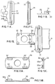
- the buckle 25, as shown in Figs. 6A and 6B, is formed at the front end of its narrow portion with an engaging hole 29 for engagement with the engaging member 28 of the buckle attaching plate 24.
- the rear portion of the buckle 25 is formed with a slit 30 for the band 21 to be inserted therein for fixing.
- the engaging hole 29 comprises a circular through-hole portion 29a and a U-shaped grip portion 29b communicating therewith.
- the through-hole portion 29a has a diameter slightly greater than that of the head portion 28b of the engaging member 28.
- the grip portion 29b has a sufficient size for the shaft portion 28a of the engaging member 28 to fit therein.
- the grip portion 29b Is thrusted on the shaft portion 29a, of the engaging member 28 to fit the buckle 25 between the upper surface of the buckle attaching plate 24 and the head portion 28b.
- the buckle 25 can be mounted on the buckle attaching plate 24 by a single manipulation.
- the slit 30 has a slide member 31 slidably mounted thereon, so that as shown in Figs. 7 and 8 the end of the band 21 is inserted in the slide member 31 to extend therearound and then the slide member 31 is slid, thereby attaching the buckle 25 to the end of the band 21.
- the band 21 is wrapped around the leg. Subsequently, one end portion of the band 21 is wrapped around the waist from the back to the front and then as shown In Fig. 6B, the buckles 25 attached to the ends of the band 21 in advance are mounted on the buckle attaching plate 24 by utilizing the engaging holes 29 and the engaging members 28. Finally, the opposite ends of the band are pulled to adjust the tightening force to complete the wrapping. Thereafter, the operator connects the manual pump and pressure gauge to the fluid feed tube 27 of the balloon 23 and while looking at the pressure gauge he operates the manual pump to fill the balloon 23 with fluid. The balloon 23 is Inflated toward the catheter insert ion wound to compress the latter white it Is restricted by the rigid case 22 from inflating toward the opposite side.
- the opposite ends of the band 21 can be fixed in position simply by mounting the buckles 25 on the buckle attaching plate by a single manipulation. Since the buckles 25 are separate from the rigid case 22, the insertion of the ends of the band 21 into the buckles 25 is easier. Further, since the buckle attaching plate 24 is rotatable with respect to the rigid ease and since the buckles 25 are rotatable with respect to the buckle attaching plate 24, the band can be wrapped with good fitness around the body of a patient having any figure and positional displacement or slack will not be produced even if compressive hemostasis continues for a long time, Thus, effective compressive hemostasis can be achieved.
- the engaging members 28 of the buckle attaching plate 24 and the engaging holes 29 of the buckles 25 may be made rectangular.
- the buckles 25 are not rotatable with respect to the buckle attaching plate 24; however, by suitably designing the shape of the shaft portion 28a of the engaging member 28, the buckles 25 can be made rotatable with respect to the buckle attaching plate 24 In a predetermined angle range.
- the buckles 25 can be mounted by a single manipulation on the buckle attaching plate 24 by utilizing engagement between the engaging members 28 of the buckle attaching plate 24 and the engaging holes 29 of the buckles 25; however, as shown in Fig. 12, the buckles 24 can be mounted on the buckle attaching plate 24. That is, as shown in Figs. 13A through 13C, pairs of grooved frames 32 of inverted L-shaped cross section each having an insertion groove 32a are disposed on the upper surface of the buckle attaching plate 24, the grooved frames in each pair being spaced a predetermined distance. As shown in Figs.
- each buckle 25 is bifurcated to form a pair of elastic engaging elements 33 having engaging pawls 33a.
- the buckles 25 can be mounted by a single manipulation on the buckle attaching plate 24 by inserting the elastic engaging elements 33 of the buckles 25 into the insertion grooves 32a of the grooved frames 32 of the buckle attaching plate 24 to engage the engaging pawls 33a of the elastic engaging elements 33 with the end edges of the grooved frames 32.
- the compressive hemostatic belt of the present invention is not limited in use to blood vessel catheter examinations but is also applicable to stoppage of bleeding from a wound caused by a catheter treatment, kidney or other dialysis, or an inject ion using various needles.
- the opposite ends of the band can be fixed in position simply by mounting the buckles on the buckle attaching plate by a single manipulation, so that the wrapping of the band around the body can be smoothly effected. Since the insertion of the ends of the band into the buckles is easy, the operating efficiency is greatly increased.
Landscapes
- Health & Medical Sciences (AREA)
- Life Sciences & Earth Sciences (AREA)
- Surgery (AREA)
- Engineering & Computer Science (AREA)
- Animal Behavior & Ethology (AREA)
- Vascular Medicine (AREA)
- Nuclear Medicine, Radiotherapy & Molecular Imaging (AREA)
- Veterinary Medicine (AREA)
- Public Health (AREA)
- Biomedical Technology (AREA)
- Heart & Thoracic Surgery (AREA)
- Medical Informatics (AREA)
- Molecular Biology (AREA)
- Reproductive Health (AREA)
- General Health & Medical Sciences (AREA)
- Biophysics (AREA)
- Hematology (AREA)
- Surgical Instruments (AREA)
Claims (6)
- Ceinture hémostatique à compression comprenant une seule bande (21) de fibre, de tissu non tissé ou de film non extensible ou faiblement extensible; un boítier rigide (22) fixé en une position prédéterminée sur une face de ladite bande; un ballonnet (23) logé dans ledit boítier rigide et adapté pour être gonflé en étant rempli d'un fluide; caractérisée par une plaque de fixation des boucles (24) ayant des moyens de prise (28) de part et d'autre de celle-ci, ladite plaque de fixation des boucles étant fixée d'une manière permettant la rotation audit boítier rigide (22); et une paire de boucles (25) fixées aux extrémités opposées de ladite bande et pouvant venir en prise avec lesdits moyens de prise (28) de ladite plaque de fixation des boucles.
- Ceinture hémostatique à compression selon la revendication 1, caractérisée en ce que lesdites boucles (25) sont constituées de trous de prise (29), tandis que ladite plaque de fixation des boucles (24) est pourvue d'éléments de prise (28) pouvant venir en prise avec lesdits trous de prise, lesdites boucles étant montées de manière amovible sur la plaque de fixation des boucles en utilisant la prise entre lesdits trous de prise et lesdits éléments de prise.
- Ceinture hémostatique à compression selon la revendication 2, caractérisée en ce que lesdits trous de prise (29) et lesdits éléments de prise (28) sont de forme circulaire.
- Ceinture hémostatique à compression selon la revendication 2, caractérisée en ce que lesdits trous de prise (29) et lesdits éléments de prise (28) sont de forme rectangulaire.
- Ceinture hémostatique à compression selon la revendication 1, caractérisée en ce qu'une partie prédéterminée de chacune des boucles (25) est fourchue pour former une paire d'éléments de prise souples (33) ayant des ergots de prise (33a), tandis que ladite plaque de fixation des boucles (24) est constituée d'une paire de cadres rainurés (32) ayant des rainures d'insertion (32a) destinées à recevoir lesdits éléments de prise souples, lesdits cadres étant espacés d'une distance prédéterminée en vis-à-vis, l'agencement étant tel que lesdits éléments de prise souples sont insérés dans les rainures d'insertion desdits cadres rainurés pour mettre en prise les ergots de prise des éléments de prise souples avec des bords d'extrémité des cadres rainurés de façon à monter les boucles de manière amovible sur la plaque de fixation des boucles.
- Ceinture hémostatique à compression selon la revendication 1, dans laquelle ledit ballonnet (23) a un tuyau d'alimentation de fluide (27) et un clapet anti-retour (26) monté sur ledit tuyau.
Applications Claiming Priority (12)
| Application Number | Priority Date | Filing Date | Title |
|---|---|---|---|
| JP4325049A JP2545678B2 (ja) | 1992-12-04 | 1992-12-04 | 圧迫止血用ベルト |
| JP325049/92 | 1992-12-04 | ||
| JP5193234A JPH0747072A (ja) | 1993-08-04 | 1993-08-04 | 圧迫止血ベルト |
| JP193235/93 | 1993-08-04 | ||
| JP5193235A JPH0747073A (ja) | 1993-08-04 | 1993-08-04 | 圧迫止血ベルト |
| JP193234/93 | 1993-08-04 | ||
| JP5193233A JPH0747071A (ja) | 1993-08-04 | 1993-08-04 | 圧迫止血ベルト |
| JP193233/93 | 1993-08-04 | ||
| JP202450/93 | 1993-08-17 | ||
| JP20245093A JP3342538B2 (ja) | 1993-08-17 | 1993-08-17 | 圧迫止血ベルト |
| JP5247647A JPH07100142A (ja) | 1993-10-04 | 1993-10-04 | 圧迫止血ベルトおよびこれに用いる流体流入出用ポンプ |
| JP247647/93 | 1993-10-04 |
Publications (2)
| Publication Number | Publication Date |
|---|---|
| EP0601756A1 EP0601756A1 (fr) | 1994-06-15 |
| EP0601756B1 true EP0601756B1 (fr) | 1998-09-02 |
Family
ID=27553664
Family Applications (1)
| Application Number | Title | Priority Date | Filing Date |
|---|---|---|---|
| EP93309500A Expired - Lifetime EP0601756B1 (fr) | 1992-12-04 | 1993-11-29 | Ceinture hémostatique compressive |
Country Status (3)
| Country | Link |
|---|---|
| US (1) | US5486194A (fr) |
| EP (1) | EP0601756B1 (fr) |
| DE (1) | DE69320769T2 (fr) |
Cited By (2)
| Publication number | Priority date | Publication date | Assignee | Title |
|---|---|---|---|---|
| CN109394287A (zh) * | 2018-09-19 | 2019-03-01 | 中国人民解放军陆军军医大学第附属医院 | 下肢交界处止血装置 |
| US12220255B2 (en) | 2020-07-30 | 2025-02-11 | Novotec Llc | Vessel location assistance device |
Families Citing this family (46)
| Publication number | Priority date | Publication date | Assignee | Title |
|---|---|---|---|---|
| US5792173A (en) * | 1995-07-10 | 1998-08-11 | Stuart D. Edwards | Wound closure hemostasis device |
| DE19636641A1 (de) * | 1996-09-10 | 1998-03-12 | Gesa Knapp | Kompressionsvorrichtung |
| WO1998046144A1 (fr) * | 1997-04-14 | 1998-10-22 | Advanced Closure Systems, Inc. | Dispositif d'hemostase jetable a regulation par reaction |
| US6210423B1 (en) * | 1998-01-29 | 2001-04-03 | Sinil Kim | Bone marrow shielding apparatus and method of bone marrow-shielded cancer chemotherapy |
| WO2000032113A1 (fr) * | 1998-11-27 | 2000-06-08 | Anthony Lam | Pince a artere |
| US6313370B1 (en) * | 1999-04-29 | 2001-11-06 | Morton Hyson | Medicated wrap |
| US20030009120A1 (en) * | 2000-12-13 | 2003-01-09 | Macallister Doris | Device for prevention of abnormal joint rotation |
| US20040068290A1 (en) * | 2002-03-27 | 2004-04-08 | Datascope Investment Corp. | Device and method for compressing wounds |
| DE60328343D1 (de) | 2002-07-15 | 2009-08-27 | Terumo Corp | Blutstillende Vorrichtung mit aufblasbarem Ballon |
| US7559908B2 (en) * | 2003-03-27 | 2009-07-14 | Sundaram Ravikumar | Compression apparatus for applying localized pressure to a wound or ulcer |
| US7276037B2 (en) * | 2003-03-27 | 2007-10-02 | Sun Scientific, Inc. | Compression apparatus for applying localized pressure to the venous system of the leg |
| US7775999B2 (en) * | 2004-10-01 | 2010-08-17 | Randall Brown | Apparatus and method for use of a hip brace |
| US8834517B2 (en) * | 2007-05-02 | 2014-09-16 | Compression Works, Llc | Portable pneumatic abdominal aortic tourniquet |
| US9149280B2 (en) * | 2007-05-02 | 2015-10-06 | Compression Works, Llc | Portable pneumatic abdominal aortic tourniquet with supplemental tensioning means |
| US20090124944A1 (en) * | 2007-11-13 | 2009-05-14 | Sundaram Ravikumar | Method and Assembly for Treating Venous Ulcers and Wounds |
| US20090204037A1 (en) * | 2008-02-12 | 2009-08-13 | Sundaram Ravikumar | Compression Apparatus for Applying Intermittent Pressure to the Leg |
| US20100200627A1 (en) * | 2009-01-15 | 2010-08-12 | Marc Shen | Ankle Tourniquet Holster |
| CN201426747Y (zh) * | 2009-03-13 | 2010-03-24 | 戚亚峰 | 动脉压迫止血器 |
| US9427238B2 (en) | 2009-08-07 | 2016-08-30 | The Seaberg Company, Inc. | Device for control of hemorrhage including stabilized point pressure device |
| US8920351B2 (en) | 2009-08-07 | 2014-12-30 | The Seaberg Company, Inc. | Emergency stabilization of a fractured pelvis or an injured neck |
| US8926536B2 (en) | 2009-08-07 | 2015-01-06 | The Seaberg Company, Inc. | Device and method for control of hemorrhage |
| SE535548C2 (sv) * | 2010-01-19 | 2012-09-18 | St Jude Medical Systems Ab | Kompressionsenhet och ett radialartärkompressionssystem |
| WO2011122488A1 (fr) * | 2010-03-29 | 2011-10-06 | テルモ株式会社 | Ensemble gaine d'introducteur |
| WO2013025546A1 (fr) | 2011-08-12 | 2013-02-21 | The Seaberg Company, Inc. | Dispositif et procédé de stabilisation de bassin fracturé ou de cou blessé, et de contrôle d'hémorragie |
| USD705429S1 (en) | 2012-08-29 | 2014-05-20 | Merit Medical Systems, Inc. | Medical compression bandage |
| USD705428S1 (en) | 2012-08-29 | 2014-05-20 | Merit Medical Systems, Inc. | Medical compression bandage |
| US10363046B2 (en) | 2012-12-04 | 2019-07-30 | The Seaberg Company, Inc. | Extremity tourniquet with locking buckle |
| US10258347B2 (en) | 2014-02-04 | 2019-04-16 | The Seaberg Company, Inc. | Extremity tourniquet |
| CN103040495A (zh) * | 2013-01-21 | 2013-04-17 | 宁波健世生物科技有限公司 | 复合型桡动脉止血带 |
| FR3007965B1 (fr) * | 2013-07-03 | 2015-07-17 | Patrick Lamas | Dispositif de compression hemostatique a pansement deporte |
| US10342551B2 (en) | 2013-07-12 | 2019-07-09 | Vasoinnovations Inc. | Method to stop bleeding, with short hemostasis duration using a low dose of anticoagulant |
| US9949738B2 (en) | 2013-07-12 | 2018-04-24 | Vasoinnovations, Inc. | Method to stop bleeding, with short hemostasis duration using a low dose of anticoagulant |
| US9668744B2 (en) | 2015-08-05 | 2017-06-06 | Vasoinnovations, Inc. | Apparatus and method to stop bleeding |
| US10213214B2 (en) | 2013-07-12 | 2019-02-26 | Vasoinnovations, Inc. | Method to stop bleeding, with short hemostasis duration using a low dose of anticoagulant |
| US10888334B2 (en) | 2013-07-12 | 2021-01-12 | Vasoinnovations Inc. | Apparatus and method to stop bleeding |
| US11564697B2 (en) | 2013-07-12 | 2023-01-31 | Vasoinnovations Inc. | Apparatus and method to stop bleeding |
| US9308000B2 (en) | 2013-07-12 | 2016-04-12 | Vasoinnovations, Inc. | Method of transradial catheterization, device for ulnar artery compression, and method of use |
| US9332994B2 (en) | 2013-07-12 | 2016-05-10 | Vasoinnovations, Inc. | Apparatus and method to stop bleeding |
| CA2917386A1 (fr) * | 2013-07-16 | 2015-01-22 | G.B.O. Mercier Inc. | Dispositif hemostatique |
| US9955978B2 (en) * | 2013-10-25 | 2018-05-01 | Medtronic Vascular, Inc. | Tissue compression device with multi-chamber bladder |
| CN104068907A (zh) * | 2014-07-15 | 2014-10-01 | 弭秀芳 | 充气式止血带 |
| US11523926B2 (en) * | 2014-07-31 | 2022-12-13 | Peteris Alberts Cers | Dynamic lumbar realignment system |
| CN108024818B (zh) | 2015-09-03 | 2021-07-16 | 泰尔茂株式会社 | 止血器具 |
| WO2017039005A1 (fr) | 2015-09-03 | 2017-03-09 | テルモ株式会社 | Instrument hémostatique |
| JP6885941B2 (ja) | 2016-07-06 | 2021-06-16 | テルモ株式会社 | 止血器具 |
| EP3815629B1 (fr) * | 2018-07-20 | 2025-09-03 | TERUMO Kabushiki Kaisha | Dispositif de compression |
Family Cites Families (10)
| Publication number | Priority date | Publication date | Assignee | Title |
|---|---|---|---|---|
| US3587584A (en) * | 1968-12-26 | 1971-06-28 | Orthopedic Equipment Co | Inflatable torniquet |
| IT956985B (it) * | 1972-06-30 | 1973-10-10 | Revil P | Apparecchiatura per emostasi |
| US3954109A (en) * | 1974-08-02 | 1976-05-04 | The Kendall Company | Bandage to prevent local hematoma |
| US4224945A (en) * | 1978-08-30 | 1980-09-30 | Jonathan Cohen | Inflatable expansible surgical pressure dressing |
| JPS5848293A (ja) * | 1981-09-16 | 1983-03-22 | Canon Inc | メモリのリフレツシユ装置 |
| DE4012974A1 (de) * | 1990-04-24 | 1991-10-31 | Dimitrov Pentcho | Aufblasbare manschette zur verwendung als oberarm- oder oberschenkel-manschette |
| EP0462088B1 (fr) * | 1990-06-11 | 1995-11-08 | Radi Medical Systems Ab | Dispositif de compression du fémur |
| US5139512A (en) * | 1990-10-18 | 1992-08-18 | Dreiling Leo D | Semiautomatic compress |
| DE69224675T2 (de) * | 1991-04-23 | 1998-07-02 | Sumitomo Rubber Ind | Hämostatischer Druckgürtel |
| DE69216066T2 (de) * | 1992-02-06 | 1997-04-03 | Sumitomo Rubber Ind | Hämostatischer Druckgürtel |
-
1993
- 1993-11-29 EP EP93309500A patent/EP0601756B1/fr not_active Expired - Lifetime
- 1993-11-29 DE DE69320769T patent/DE69320769T2/de not_active Expired - Fee Related
- 1993-12-02 US US08/160,214 patent/US5486194A/en not_active Expired - Lifetime
Cited By (3)
| Publication number | Priority date | Publication date | Assignee | Title |
|---|---|---|---|---|
| CN109394287A (zh) * | 2018-09-19 | 2019-03-01 | 中国人民解放军陆军军医大学第附属医院 | 下肢交界处止血装置 |
| CN109394287B (zh) * | 2018-09-19 | 2020-10-13 | 中国人民解放军陆军军医大学第一附属医院 | 下肢交界处止血装置 |
| US12220255B2 (en) | 2020-07-30 | 2025-02-11 | Novotec Llc | Vessel location assistance device |
Also Published As
| Publication number | Publication date |
|---|---|
| DE69320769T2 (de) | 1999-01-14 |
| DE69320769D1 (de) | 1998-10-08 |
| US5486194A (en) | 1996-01-23 |
| EP0601756A1 (fr) | 1994-06-15 |
Similar Documents
| Publication | Publication Date | Title |
|---|---|---|
| US5486194A (en) | Compressive hemostatic belt | |
| US5433724A (en) | Compressive hemostatic belt | |
| US10610238B2 (en) | Hemostatic device | |
| US5464420A (en) | Compressive hemostatic belt | |
| US12484911B2 (en) | Inflatable radial artery compression device with cinching wristband and method of use | |
| WO2011065914A1 (fr) | Système de compression | |
| EP0554602B1 (fr) | Ceinture hémostatique à pression | |
| EP0514026B1 (fr) | Ceinture hémostatique compressive | |
| JP3192191B2 (ja) | 圧迫止血用ベルト | |
| JP3342538B2 (ja) | 圧迫止血ベルト | |
| JP3302182B2 (ja) | 圧迫止血用ベルト | |
| JP2591879B2 (ja) | 圧迫止血用ベルト | |
| CN217488744U (zh) | 一种可穿脱股动脉压迫器 | |
| KR20240151461A (ko) | 지혈 밴드 세트 | |
| JP2574953Y2 (ja) | 圧迫止血用ベルト | |
| JP2545678B2 (ja) | 圧迫止血用ベルト | |
| CN220967359U (zh) | 一种股静脉置管拔出后加压止血绑带 | |
| CN217310457U (zh) | 一种tace术后包扎敷料 | |
| CN218792386U (zh) | 一种新型便捷式止血带 | |
| CN219289581U (zh) | 医用股动脉压迫止血盐袋套 | |
| CN222367745U (zh) | 一种用于桡动脉穿刺点压迫止血器 | |
| CN213249465U (zh) | 透析导管专用止血带 | |
| JPH0747073A (ja) | 圧迫止血ベルト | |
| JPH078500A (ja) | 圧迫止血ベルト | |
| JPH07143990A (ja) | 圧迫止血用ベルト |
Legal Events
| Date | Code | Title | Description |
|---|---|---|---|
| PUAI | Public reference made under article 153(3) epc to a published international application that has entered the european phase |
Free format text: ORIGINAL CODE: 0009012 |
|
| AK | Designated contracting states |
Kind code of ref document: A1 Designated state(s): DE FR GB |
|
| 17P | Request for examination filed |
Effective date: 19940701 |
|
| 17Q | First examination report despatched |
Effective date: 19960104 |
|
| GRAG | Despatch of communication of intention to grant |
Free format text: ORIGINAL CODE: EPIDOS AGRA |
|
| GRAG | Despatch of communication of intention to grant |
Free format text: ORIGINAL CODE: EPIDOS AGRA |
|
| GRAH | Despatch of communication of intention to grant a patent |
Free format text: ORIGINAL CODE: EPIDOS IGRA |
|
| GRAH | Despatch of communication of intention to grant a patent |
Free format text: ORIGINAL CODE: EPIDOS IGRA |
|
| GRAA | (expected) grant |
Free format text: ORIGINAL CODE: 0009210 |
|
| AK | Designated contracting states |
Kind code of ref document: B1 Designated state(s): DE FR GB |
|
| REF | Corresponds to: |
Ref document number: 69320769 Country of ref document: DE Date of ref document: 19981008 |
|
| ET | Fr: translation filed | ||
| PLBE | No opposition filed within time limit |
Free format text: ORIGINAL CODE: 0009261 |
|
| 26N | No opposition filed | ||
| REG | Reference to a national code |
Ref country code: GB Ref legal event code: IF02 |
|
| PGFP | Annual fee paid to national office [announced via postgrant information from national office to epo] |
Ref country code: DE Payment date: 20071122 Year of fee payment: 15 |
|
| PGFP | Annual fee paid to national office [announced via postgrant information from national office to epo] |
Ref country code: GB Payment date: 20071128 Year of fee payment: 15 Ref country code: FR Payment date: 20071108 Year of fee payment: 15 |
|
| GBPC | Gb: european patent ceased through non-payment of renewal fee |
Effective date: 20081129 |
|
| REG | Reference to a national code |
Ref country code: FR Ref legal event code: ST Effective date: 20090731 |
|
| PG25 | Lapsed in a contracting state [announced via postgrant information from national office to epo] |
Ref country code: DE Free format text: LAPSE BECAUSE OF NON-PAYMENT OF DUE FEES Effective date: 20090603 |
|
| PG25 | Lapsed in a contracting state [announced via postgrant information from national office to epo] |
Ref country code: GB Free format text: LAPSE BECAUSE OF NON-PAYMENT OF DUE FEES Effective date: 20081129 |
|
| PG25 | Lapsed in a contracting state [announced via postgrant information from national office to epo] |
Ref country code: FR Free format text: LAPSE BECAUSE OF NON-PAYMENT OF DUE FEES Effective date: 20081130 |