EP0602368A1 - Circuit d'allumage et d'alimentation pour lampes à décharge haute pression - Google Patents
Circuit d'allumage et d'alimentation pour lampes à décharge haute pression Download PDFInfo
- Publication number
- EP0602368A1 EP0602368A1 EP93117792A EP93117792A EP0602368A1 EP 0602368 A1 EP0602368 A1 EP 0602368A1 EP 93117792 A EP93117792 A EP 93117792A EP 93117792 A EP93117792 A EP 93117792A EP 0602368 A1 EP0602368 A1 EP 0602368A1
- Authority
- EP
- European Patent Office
- Prior art keywords
- current
- capacitor
- pressure gas
- lamp
- power
- Prior art date
- Legal status (The legal status is an assumption and is not a legal conclusion. Google has not performed a legal analysis and makes no representation as to the accuracy of the status listed.)
- Granted
Links
- 239000003990 capacitor Substances 0.000 claims abstract description 58
- 230000001105 regulatory effect Effects 0.000 claims description 6
- 229910052715 tantalum Inorganic materials 0.000 claims description 2
- GUVRBAGPIYLISA-UHFFFAOYSA-N tantalum atom Chemical compound [Ta] GUVRBAGPIYLISA-UHFFFAOYSA-N 0.000 claims description 2
- 230000001419 dependent effect Effects 0.000 abstract description 4
- 238000007599 discharging Methods 0.000 description 3
- 230000033228 biological regulation Effects 0.000 description 2
- 238000010586 diagram Methods 0.000 description 2
- 238000000034 method Methods 0.000 description 2
- 241000158147 Sator Species 0.000 description 1
- 238000002485 combustion reaction Methods 0.000 description 1
- 230000000694 effects Effects 0.000 description 1
- 230000006641 stabilisation Effects 0.000 description 1
- 238000011105 stabilization Methods 0.000 description 1
- 230000000087 stabilizing effect Effects 0.000 description 1
- 230000007704 transition Effects 0.000 description 1
Images
Classifications
-
- H—ELECTRICITY
- H05—ELECTRIC TECHNIQUES NOT OTHERWISE PROVIDED FOR
- H05B—ELECTRIC HEATING; ELECTRIC LIGHT SOURCES NOT OTHERWISE PROVIDED FOR; CIRCUIT ARRANGEMENTS FOR ELECTRIC LIGHT SOURCES, IN GENERAL
- H05B41/00—Circuit arrangements or apparatus for igniting or operating discharge lamps
- H05B41/14—Circuit arrangements
- H05B41/26—Circuit arrangements in which the lamp is fed by power derived from DC by means of a converter, e.g. by high-voltage DC
- H05B41/28—Circuit arrangements in which the lamp is fed by power derived from DC by means of a converter, e.g. by high-voltage DC using static converters
- H05B41/288—Circuit arrangements in which the lamp is fed by power derived from DC by means of a converter, e.g. by high-voltage DC using static converters with semiconductor devices and specially adapted for lamps without preheating electrodes, e.g. for high-intensity discharge lamps, high-pressure mercury or sodium lamps or low-pressure sodium lamps
- H05B41/2881—Load circuits; Control thereof
- H05B41/2882—Load circuits; Control thereof the control resulting from an action on the static converter
-
- H—ELECTRICITY
- H05—ELECTRIC TECHNIQUES NOT OTHERWISE PROVIDED FOR
- H05B—ELECTRIC HEATING; ELECTRIC LIGHT SOURCES NOT OTHERWISE PROVIDED FOR; CIRCUIT ARRANGEMENTS FOR ELECTRIC LIGHT SOURCES, IN GENERAL
- H05B41/00—Circuit arrangements or apparatus for igniting or operating discharge lamps
- H05B41/14—Circuit arrangements
- H05B41/36—Controlling
- H05B41/38—Controlling the intensity of light
- H05B41/382—Controlling the intensity of light during the transitional start-up phase
- H05B41/386—Controlling the intensity of light during the transitional start-up phase for speeding-up the lighting-up
-
- Y—GENERAL TAGGING OF NEW TECHNOLOGICAL DEVELOPMENTS; GENERAL TAGGING OF CROSS-SECTIONAL TECHNOLOGIES SPANNING OVER SEVERAL SECTIONS OF THE IPC; TECHNICAL SUBJECTS COVERED BY FORMER USPC CROSS-REFERENCE ART COLLECTIONS [XRACs] AND DIGESTS
- Y02—TECHNOLOGIES OR APPLICATIONS FOR MITIGATION OR ADAPTATION AGAINST CLIMATE CHANGE
- Y02B—CLIMATE CHANGE MITIGATION TECHNOLOGIES RELATED TO BUILDINGS, e.g. HOUSING, HOUSE APPLIANCES OR RELATED END-USER APPLICATIONS
- Y02B20/00—Energy efficient lighting technologies, e.g. halogen lamps or gas discharge lamps
Definitions
- the invention relates to a ballast for starting and operating high-pressure gas discharge lamps, which is fed from a battery, with at least one current and / or power-regulated voltage converter, which is connected via an ignition device to a high-pressure gas discharge lamp and which has an input with a Current / power control is connected, with an output on the current / power control via which a current / power setpoint is supplied to the voltage converter, with a comparator which generates a switching signal as a function of the input signal and with a capacitor which as a function of the generated switching signal is charged with a first time constant and discharged with a second time constant and the voltage of which determines the level and duration of an additional power supplied to the high-pressure gas discharge lamp after ignition, which depends on the operating state of the high-pressure gas discharge lamp and on its ma maximum permitted lamp current is limited.
- a ballast for starting and operating high-pressure gas discharge lamps is known from German patent application P 40 15 398 A1, in which the ballast is fed from the battery of a motor vehicle.
- the known ballast has a current and line-regulated voltage converter which is designed as an inverter and generates an AC voltage from the DC voltage applied by the vehicle battery.
- the voltage converter is connected to a high-pressure gas discharge lamp via an ignition device.
- the voltage converter is connected to a current / power control.
- the current / power control has an output via which a current / power setpoint is supplied to the voltage converter.
- the current / power control has a circuit arrangement by means of which the high-pressure gas discharge lamp is supplied with an additional power from the voltage converter directly after the ignition depends on the respective operating state of the high-pressure gas discharge lamp and is limited by its maximum permissible lamp current.
- the known circuit arrangement has a comparator which generates a switching signal depending on the state of charge of a first capacitor and the known circuit arrangement has a second capacitor which is charged with a first time constant or discharged with a second time constant depending on the generated switching signal is, the voltage of the capacitor determines the amount and duration of the additional power supplied to the high-pressure gas discharge lamp.
- the first capacitor is charged and discharged again with a third time constant, which determines the time for which the second capacitor is not charged.
- the known ballast for starting and operating high-pressure gas discharge lamps it turns out to be disadvantageous that two capacitors are required to measure the additional power, the time constant determined by the first capacitor in conjunction with the connected resistor being responsible for switching the comparator , is independent of the lamp.
- the high-pressure gas discharge lamp is supplied with an additional power which does not correspond to the required additional power, as a result of which a reliable and rapid transition of the high-pressure gas discharge lamp into a stable, stationary operating state is frequently not achieved.
- the second capacitor which determines the amount and duration of the additional services to be supplied to the high-pressure gas discharge lamp directly after the ignition, when the ballast is switched off, in addition to the intended discharge in accordance with the predetermined time constant and by using the Leakage currents occurring to the connected components of the current / power control are discharged, which means that when the ballast is put into operation, an additional power is supplied to the high-pressure gas discharge lamp which does not correspond to the required additional power and the required lamp power of the high-pressure gas discharge lamp cannot be maintained in stationary operation, because the second capacitor does not reach the desired state of charge due to its own leakage currents.
- the invention has for its object to provide a simple and inexpensive ballast in which the most exact, lamp-dependent control of the current supplied to the lamp or the power supplied to the lamp is ensured both in the start-up phase and in the stationary operation of the high-pressure gas discharge lamp.
- the object is achieved in that an input signal corresponding to the lamp voltage is present at the input, that the time elements determining the time constants are connected to the other components of the current / power control via low-leakage rectifiers, so that no back-discharge of the condensers sator over these components is possible and that a high-resistance leakage current compensation circuit compensates for the leakage current of the capacitor and stabilizes its voltage in steady-state operation, which is required for a stable nominal operating power of the lamp.
- an input signal corresponding to the lamp voltage is present at the input, because it is thus determined in a particularly simple and cost-effective manner by measuring the lamp voltage alone from when the additional power is withdrawn after starting and determining the operating status of the lamp by measuring the Lamp current is not required.
- the difference formed by the subtractor from the reference voltage and the voltage applied to the capacitor thus corresponds in a simple manner to the required time profile of the power to be supplied to the high-pressure gas discharge lamp in a simple manner with low component expenditure.
- time constants determining the time constants are connected to the other components of the current / power control via low-leakage rectifiers, because it is thus avoided in a simple and inexpensive manner that when the ballast is switched off and the capacitor in the entire circuit is switched off has the highest potential, this is discharged by other components of the current / lamp control, which would lead to a falsification of the height and the duration of the additional power supplied to the high-pressure gas discharge lamp when the ballast is switched on.
- the time constants determining the time constants With low-leakage rectifiers, it is thus ensured in a simple and cost-effective manner that the predetermined time constants for discharging the capacitor are kept as well as possible by avoiding discharge currents through other components and thus the steady-state operating state of the high-pressure gas discharge lamp quickly , safely and without damaging the lamp z. B. is achieved by applying too high a current.
- a high-resistance leakage current compensation circuit compensates for the leakage current of the capacitor and stabilizes the voltage from the capacitor with the capacitor fully charged to the voltage required for a stable nominal operating power of the lamp, because the nominal operating power of the high-pressure components is thus simple and inexpensive. Gas discharge lamp is adhered to as best as possible in stationary operation.
- the leakage current compensation circuit is designed as an operational amplifier whose non-inverting input is connected to a reference voltage source, whose inverting input is connected to a terminal and whose output is connected to the terminal via a high-resistance fourth resistor and this terminal on the one hand via the rectifier to the Capacitor and on the other hand connected to the output of the current / power control via a difference-forming circuit, there is the advantage of a particularly simple and reliable circuit arrangement for regulating the nominal operating power of the high-pressure gas discharge lamp to an exact value, the time constants being used by using a high-resistance fourth resistor not be influenced or only slightly influenced for charging the capacitor. The latter advantage is achieved in particular if the time constant determined by the capacitor and the fourth resistor is at least one order of magnitude higher than the time constants determined by the time elements for the charging and discharging of the capacitor.
- a particularly simple and inexpensive embodiment is made possible, both in the start-up phase and in steady-state operation of the high-pressure gas discharge lamp, the most exact possible lamp-dependent regulation of the current supplied to the lamp or guarantees the power supplied to the lamp, the use of a low-resistance first resistor to charge the capacitor via the third resistor having no negative influence on the charging process of the capacitor.
- the resistance value of the first resistor is at least one order of magnitude smaller than the resistance values of the second and the third resistor.
- the low-leakage rectifiers are the base-collector diodes of bipolar transistors.
- the capacitor is a low-leakage tantalum capacitor, because this ensures that even at high temperatures in the ballast, for example in an arrangement near the lamp, the desired charging and discharging characteristics are not influenced by excessive leakage currents.
- ballast for starting and operating high-pressure gas discharge lamps in motor vehicles, since the demands made on motor vehicles for the operation of high-pressure gas discharge lamps in terms of reliability during commissioning, the times for reaching certain light outputs and compliance with a constant light output by the ballast.
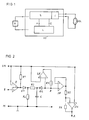
- FIG. 1 shows a block diagram of a ballast according to the invention (VG) for starting and operating high pressure gas discharge lamps (GDL).
- the ballast (VG) is powered by a battery (B) z.
- B. can be the vehicle battery of a motor vehicle.
- the ballast has at least one current and power-controlled voltage converter (S) which is connected to a high-pressure gas discharge lamp (GDL) via an ignition device (Z).
- the ignition device (Z) is part of the ballast (VG).
- the ignition device (Z) can also be arranged separately.
- the at least one current and power-regulated voltage converter (S) is a DC / DC converter, which is followed by a bridge switch (not shown here) for driving an AC high-pressure gas discharge lamp (GDL).
- a bridge switch not shown here
- GDL AC high-pressure gas discharge lamp
- the at least one current and power regulated voltage converter (S) this is connected to a current / power control (L).
- the current / power control (L) has an input (E) at which an input signal corresponding to the lamp voltage is present.
- the current / power control (L) has an output (A) via which a current / power setpoint is supplied to the voltage converter (S).
- GDL high pressure gas discharge lamp
- the current / power control (L) has a circuit arrangement shown in FIG. 2 for generating an additional power directly after the ignition of the high-pressure gas discharge lamp (GDL), which is dependent on the lamp operating state and is limited by the maximum permissible lamp current .
- the input (E), to which an input signal corresponding to the lamp voltage is present, is connected to the non-inverting input of the comparator (O).
- the inverting input of the comparator (O) is connected to the reference voltage source (UR).
- the comparator (O) has an output which, depending on the switching state of the comparator (O), is either open or connected to ground (M).
- This output of the comparator is connected on the one hand via a low-resistance first resistor (R1) to the reference voltage source (UR) and on the other hand to the anode of the first low-leakage rectifier (G1).
- the cathode of the first rectifier (G1) is connected on the one hand via a second resistor (R2) to ground (M) and on the other hand via a third resistor (R3) and the capacitor (C) to ground (M).
- the capacitor (C) is also connected to the cathode of the second low-leakage rectifier (G2), the anode of which is connected to the inverting input of the leakage current compensation circuit (LK) and via the terminal (K) to the non-inverting input of a voltage follower (SF) connected is.
- the non-inverting input of the leakage current compensation circuit (LK) is connected to the reference voltage source (UR).
- the output of the leakage current compensation circuit (LK) is connected via a high-resistance fourth resistor (R4) to stabilize the voltage at the terminal (K).
- the output of the voltage follower (SF) is connected in a known manner both to its inverting input and via a fifth resistor (R5) to the inverting input of a subtractor (SH).
- the non-inverting input of the subtractor (SH) is also connected to the reference voltage source (UR).
- the output of the subtractor (SH) is connected on the one hand via a sixth resistor (R6) to the inverting input of the subtractor (SH) and on the other hand to the output (A) of the current / power control (L).
- the sub-emitter (SH) forms a sub-emitter circuit with the resistors (R5, R6).
- the capacitor (C) can be used to reduce leakage currents as a low leakage tan valley capacitor.
- the low-leakage rectifiers (G1, G2) which are shown in FIG. 2 as diodes, can be replaced by transistors and, in particular, by bipolar transistors for an economical implementation of the circuit, the base-collector diodes of the bipolar transistors being used by the low-leakage rectifiers (G1 , G2) replace.
- the resistance value of the fourth resistor (R4) is at least one order of magnitude larger than the resistance values of the second and the third resistor (R2, R3) and the resistance value of the first resistor (R1) is at least one order of magnitude smaller than the resistance values of the second and third resistor (R2, R3).
- the capacitor (C) is discharged according to the preselected time constant via the resistors (R3, R2), whereby possible leakage currents to other circuit components of the current / power control (L) through the low-leakage rectifiers (G1, G2) in the best possible way be avoided.
- the capacitor (C) is completely discharged, i. H. the voltage across the capacitor (C) has a minimum value.
- the high-pressure gas discharge lamp (GDL) is ignited in accordance with FIG. 1 by the voltage provided by the at least one voltage converter (S) and the ignition device (Z).
- An input signal corresponding to the lamp voltage is present at the input (E) of the circuit arrangement according to FIG. 2.
- This input signal at the input (E) is compared by the comparator (O) with a reference voltage from the reference voltage source (UR). If the lamp voltage exceeds a predetermined lamp limit voltage, the comparator (O) generates a switching signal, the internal ground contact is opened and the output of the comparator (O) assumes the open switching state.
- the capacitor (C) is thus charged via the third resistor (R3) and the low-resistance first resistor (R1) from the reference voltage source (UR) in accordance with the time constant specified by the capacitor (C) and the third resistor (R3).
- the voltage at the output (A) of the current / power control is accordingly starting with a maximum value that corresponds to a maximum power corresponding to a fully discharged capacitor (C) according to the predetermined time constant up to a power setpoint for the steady-state operating state of the high-pressure gas discharge lamp (GDL ) corresponding voltage value reduced.
- the voltage at the terminal (K) is stabilized by the leakage current compensation circuit (LK) after reaching the maximum voltage value of the capacitor (C), which voltage at the terminal (K) stabilized as a function of the voltage value of the capacitor (C) to the voltage of the reference voltage source (UR).
- the capacitor (C) has a voltage depending on the operating time of the high-pressure gas discharge lamp (GDL), which is between the minimum voltage (lamp was not in operation) and the maximum voltage (lamp is hot) varies.
- the capacitor (C) is then discharged via these resistors in accordance with a time constant which is predetermined by the capacitor (C), the third resistor (R3) and the second resistor (R2). If the ballast (VG) is switched on again, the increased power required by the high-pressure gas discharge lamp (GDL) corresponds to the difference that the sub-emitter (SH) forms from the reference voltage (UR) and the residual voltage on the capacitor (C), so that the high-pressure gas discharge lamp (GDL) is supplied in a simple and cost-effective manner in each operating state with the exactly required current or the exactly required power.
- the resistance value of the fourth resistor (R4) is chosen so high that it and the capacitor (C) have one Forms time constant that is at least one order of magnitude above all other effective time constants of the circuit of the current / power control (L) and on the other hand small enough that the largest possible Leakage current of the capacitor (C) can still be compensated.
Landscapes
- Circuit Arrangements For Discharge Lamps (AREA)
Applications Claiming Priority (2)
| Application Number | Priority Date | Filing Date | Title |
|---|---|---|---|
| DE4242174 | 1992-12-15 | ||
| DE4242174A DE4242174A1 (de) | 1992-12-15 | 1992-12-15 | Vorschaltgerät zum Starten und Betreiben von Hochdruck-Gasentladungslampen |
Publications (2)
| Publication Number | Publication Date |
|---|---|
| EP0602368A1 true EP0602368A1 (fr) | 1994-06-22 |
| EP0602368B1 EP0602368B1 (fr) | 1997-10-08 |
Family
ID=6475246
Family Applications (1)
| Application Number | Title | Priority Date | Filing Date |
|---|---|---|---|
| EP93117792A Expired - Lifetime EP0602368B1 (fr) | 1992-12-15 | 1993-11-03 | Circuit d'allumage et d'alimentation pour lampes à décharge haute pression |
Country Status (3)
| Country | Link |
|---|---|
| EP (1) | EP0602368B1 (fr) |
| AT (1) | ATE159141T1 (fr) |
| DE (2) | DE4242174A1 (fr) |
Families Citing this family (4)
| Publication number | Priority date | Publication date | Assignee | Title |
|---|---|---|---|---|
| JP3440667B2 (ja) * | 1995-12-27 | 2003-08-25 | 株式会社デンソー | 放電灯点灯装置 |
| DE102005058574B4 (de) * | 2005-12-08 | 2016-03-24 | Hella Kgaa Hueck & Co. | Vorrichtung zum Steuern der Zusatzleistung einer Gasentladungslampe mit einem Oszillator, dessen Frequenz zum Ersetzen eines RC-Zeitgliedes geändert wird |
| DE102006010703B4 (de) * | 2006-03-08 | 2015-08-20 | Hella Kgaa Hueck & Co. | Schaltungsanordnung und Verfahren zur Steuerung einer Zusatzleistung beim Einschalten einer Hochdruckgasentladungslampe |
| DE102006011353A1 (de) * | 2006-03-11 | 2007-10-04 | Hella Kgaa Hueck & Co. | Schaltungsanordnung zur Regelung der Ausgangsleistung eines Vorschaltgeräts für eine Hochdruckgasentladungslampe |
Citations (3)
| Publication number | Priority date | Publication date | Assignee | Title |
|---|---|---|---|---|
| DE4017415A1 (de) * | 1989-06-02 | 1991-02-14 | Koito Mfg Co Ltd | Lampenstromkreis fuer eine hochdruck-entladungslampe fuer fahrzeuge |
| EP0415496A2 (fr) * | 1989-08-31 | 1991-03-06 | Philips Patentverwaltung GmbH | Circuit pour alimenter une lampe à décharge |
| DE4015398A1 (de) * | 1990-05-14 | 1991-11-21 | Hella Kg Hueck & Co | Verfahren und einrichtung zum starten einer hochdruckgasentladungslampe in kraftfahrzeugen |
Family Cites Families (2)
| Publication number | Priority date | Publication date | Assignee | Title |
|---|---|---|---|---|
| DE3843029A1 (de) * | 1988-12-21 | 1990-06-28 | Hella Kg Hueck & Co | Einrichtung zum zuenden und betreiben elektrischer gasentladungslampen |
| DE3925993A1 (de) * | 1989-08-05 | 1991-02-07 | Bosch Gmbh Robert | Verfahren zum zuenden einer gasentladungslampe |
-
1992
- 1992-12-15 DE DE4242174A patent/DE4242174A1/de not_active Withdrawn
-
1993
- 1993-11-03 DE DE59307496T patent/DE59307496D1/de not_active Expired - Lifetime
- 1993-11-03 EP EP93117792A patent/EP0602368B1/fr not_active Expired - Lifetime
- 1993-11-03 AT AT93117792T patent/ATE159141T1/de not_active IP Right Cessation
Patent Citations (3)
| Publication number | Priority date | Publication date | Assignee | Title |
|---|---|---|---|---|
| DE4017415A1 (de) * | 1989-06-02 | 1991-02-14 | Koito Mfg Co Ltd | Lampenstromkreis fuer eine hochdruck-entladungslampe fuer fahrzeuge |
| EP0415496A2 (fr) * | 1989-08-31 | 1991-03-06 | Philips Patentverwaltung GmbH | Circuit pour alimenter une lampe à décharge |
| DE4015398A1 (de) * | 1990-05-14 | 1991-11-21 | Hella Kg Hueck & Co | Verfahren und einrichtung zum starten einer hochdruckgasentladungslampe in kraftfahrzeugen |
Also Published As
| Publication number | Publication date |
|---|---|
| DE4242174A1 (de) | 1994-06-16 |
| EP0602368B1 (fr) | 1997-10-08 |
| ATE159141T1 (de) | 1997-10-15 |
| DE59307496D1 (de) | 1997-11-13 |
Similar Documents
| Publication | Publication Date | Title |
|---|---|---|
| EP0459126B1 (fr) | Procédé et dispositif pour l'amorçage d'une lampe à décharge haute pression dans des véhicules | |
| DE2903224C2 (de) | Schaltungsanordnung zum Zünden und Speisen einer mit einer vorheizbaren Elektrode versehenen Metalldampfentladungslampe | |
| DE4129557C2 (de) | Stromversorgungsschaltung für eine Gasentladungslampe in einem Fahrzeug | |
| DE60212818T2 (de) | Regelungsvorrichtung und verfahren für einen gleichstrom/gleichstrom-wandler | |
| DE19819510B4 (de) | Schaltungsanordnung zum Zünden und Betreiben einer Entladungslampe | |
| EP0359860A1 (fr) | Dispositif et procédé de mise en oeuvre d'au moins une lampe à décharge | |
| EP0561316A1 (fr) | Circuit de commande pour un commutateur semi-conducteur commandé en tension | |
| DE3246454A1 (de) | Wechselrichter mit einem einen reihenresonanzkreis und eine entladungslampe enthaltenden lastkreis | |
| DE4002334A1 (de) | Lampen-beleuchtungsschaltkreis mit ueberlastschutz | |
| DE69915164T2 (de) | Gerät für eine Entladungslampe | |
| DE19654539B4 (de) | Entladungslampensteuerung | |
| DE69315761T2 (de) | Geschützter Umrichter zur Steuerung einer Entladungslampe | |
| DE19843643B4 (de) | Schaltungsanordnung zum Starten und Betreiben einer Hochdruck-Entladungslampe | |
| EP0233191B1 (fr) | Circuit de reglage de l'alimentation haute tension d'un filtre electrostatique | |
| WO1988000770A1 (fr) | Etage final de circuit a pont | |
| EP0054301A1 (fr) | Dispositif d'allumage pour lampe à décharge à basse pression | |
| EP0534280B1 (fr) | Ballast pour faire démarrer et mettre en service des lampes de décharge à gaz à haute pression | |
| EP0602368B1 (fr) | Circuit d'allumage et d'alimentation pour lampes à décharge haute pression | |
| DE69428732T2 (de) | Schaltung zum Starten einer Hochdruckgasentladungslampe mit einer Zusatzleistung | |
| EP0399201A1 (fr) | Système d'alarme pour lumière de flash | |
| DE102004050060B4 (de) | Tiefsetzerschaltung | |
| EP0544998B1 (fr) | Circuit pour faire démarrer et mettre en service des lampes luminescentes à gaz à haute pression | |
| EP1047286B1 (fr) | Starter pour lampe à décharge dans un véhicule | |
| EP0737379A1 (fr) | Transformateur de tension | |
| DE2414393C2 (de) | Kraftfahrzeug-Lichtanlage |
Legal Events
| Date | Code | Title | Description |
|---|---|---|---|
| PUAI | Public reference made under article 153(3) epc to a published international application that has entered the european phase |
Free format text: ORIGINAL CODE: 0009012 |
|
| 17P | Request for examination filed |
Effective date: 19940422 |
|
| AK | Designated contracting states |
Kind code of ref document: A1 Designated state(s): AT DE FR GB IT |
|
| GRAG | Despatch of communication of intention to grant |
Free format text: ORIGINAL CODE: EPIDOS AGRA |
|
| 17Q | First examination report despatched |
Effective date: 19970124 |
|
| GRAH | Despatch of communication of intention to grant a patent |
Free format text: ORIGINAL CODE: EPIDOS IGRA |
|
| GRAH | Despatch of communication of intention to grant a patent |
Free format text: ORIGINAL CODE: EPIDOS IGRA |
|
| GRAA | (expected) grant |
Free format text: ORIGINAL CODE: 0009210 |
|
| ITF | It: translation for a ep patent filed | ||
| AK | Designated contracting states |
Kind code of ref document: B1 Designated state(s): AT DE FR GB IT |
|
| REF | Corresponds to: |
Ref document number: 159141 Country of ref document: AT Date of ref document: 19971015 Kind code of ref document: T |
|
| REF | Corresponds to: |
Ref document number: 59307496 Country of ref document: DE Date of ref document: 19971113 |
|
| GBT | Gb: translation of ep patent filed (gb section 77(6)(a)/1977) |
Effective date: 19971113 |
|
| ET | Fr: translation filed | ||
| PLBE | No opposition filed within time limit |
Free format text: ORIGINAL CODE: 0009261 |
|
| STAA | Information on the status of an ep patent application or granted ep patent |
Free format text: STATUS: NO OPPOSITION FILED WITHIN TIME LIMIT |
|
| 26N | No opposition filed | ||
| PGFP | Annual fee paid to national office [announced via postgrant information from national office to epo] |
Ref country code: GB Payment date: 20011022 Year of fee payment: 9 |
|
| PGFP | Annual fee paid to national office [announced via postgrant information from national office to epo] |
Ref country code: AT Payment date: 20011123 Year of fee payment: 9 |
|
| REG | Reference to a national code |
Ref country code: GB Ref legal event code: IF02 |
|
| PG25 | Lapsed in a contracting state [announced via postgrant information from national office to epo] |
Ref country code: GB Free format text: LAPSE BECAUSE OF NON-PAYMENT OF DUE FEES Effective date: 20021103 Ref country code: AT Free format text: LAPSE BECAUSE OF NON-PAYMENT OF DUE FEES Effective date: 20021103 |
|
| GBPC | Gb: european patent ceased through non-payment of renewal fee | ||
| PGFP | Annual fee paid to national office [announced via postgrant information from national office to epo] |
Ref country code: FR Payment date: 20051108 Year of fee payment: 13 |
|
| PGFP | Annual fee paid to national office [announced via postgrant information from national office to epo] |
Ref country code: IT Payment date: 20061130 Year of fee payment: 14 |
|
| REG | Reference to a national code |
Ref country code: FR Ref legal event code: ST Effective date: 20070731 |
|
| PG25 | Lapsed in a contracting state [announced via postgrant information from national office to epo] |
Ref country code: FR Free format text: LAPSE BECAUSE OF NON-PAYMENT OF DUE FEES Effective date: 20061130 |
|
| PG25 | Lapsed in a contracting state [announced via postgrant information from national office to epo] |
Ref country code: IT Free format text: LAPSE BECAUSE OF NON-PAYMENT OF DUE FEES Effective date: 20071103 |
|
| PGFP | Annual fee paid to national office [announced via postgrant information from national office to epo] |
Ref country code: DE Payment date: 20121031 Year of fee payment: 20 |
|
| REG | Reference to a national code |
Ref country code: DE Ref legal event code: R071 Ref document number: 59307496 Country of ref document: DE |
|
| PG25 | Lapsed in a contracting state [announced via postgrant information from national office to epo] |
Ref country code: DE Free format text: LAPSE BECAUSE OF EXPIRATION OF PROTECTION Effective date: 20131105 |