EP0602416A1 - Methode zur Kontrolle eines Durchflusszytometers mit vakuumgesteuerter Strömung - Google Patents
Methode zur Kontrolle eines Durchflusszytometers mit vakuumgesteuerter Strömung Download PDFInfo
- Publication number
- EP0602416A1 EP0602416A1 EP93118851A EP93118851A EP0602416A1 EP 0602416 A1 EP0602416 A1 EP 0602416A1 EP 93118851 A EP93118851 A EP 93118851A EP 93118851 A EP93118851 A EP 93118851A EP 0602416 A1 EP0602416 A1 EP 0602416A1
- Authority
- EP
- European Patent Office
- Prior art keywords
- flow cell
- flow
- cell
- vacuum
- sample
- Prior art date
- Legal status (The legal status is an assumption and is not a legal conclusion. Google has not performed a legal analysis and makes no representation as to the accuracy of the status listed.)
- Granted
Links
- 238000000034 method Methods 0.000 title claims description 11
- 239000012530 fluid Substances 0.000 claims abstract description 56
- 238000004458 analytical method Methods 0.000 claims abstract description 21
- 239000002699 waste material Substances 0.000 claims abstract description 15
- 238000004891 communication Methods 0.000 claims abstract description 12
- 230000002441 reversible effect Effects 0.000 claims abstract description 9
- 238000011010 flushing procedure Methods 0.000 claims abstract description 3
- 238000012360 testing method Methods 0.000 claims description 17
- 239000007789 gas Substances 0.000 claims description 5
- 230000010349 pulsation Effects 0.000 claims description 5
- IJGRMHOSHXDMSA-UHFFFAOYSA-N Atomic nitrogen Chemical compound N#N IJGRMHOSHXDMSA-UHFFFAOYSA-N 0.000 claims description 4
- 239000000356 contaminant Substances 0.000 claims description 4
- QVGXLLKOCUKJST-UHFFFAOYSA-N atomic oxygen Chemical compound [O] QVGXLLKOCUKJST-UHFFFAOYSA-N 0.000 claims description 2
- 239000000463 material Substances 0.000 claims description 2
- 229910052757 nitrogen Inorganic materials 0.000 claims description 2
- 239000001301 oxygen Substances 0.000 claims description 2
- 229910052760 oxygen Inorganic materials 0.000 claims description 2
- 230000004913 activation Effects 0.000 claims 1
- 239000007788 liquid Substances 0.000 abstract description 6
- 230000001276 controlling effect Effects 0.000 abstract description 5
- 230000001105 regulatory effect Effects 0.000 abstract description 5
- 239000002245 particle Substances 0.000 abstract description 3
- 230000001464 adherent effect Effects 0.000 abstract 1
- 230000015572 biosynthetic process Effects 0.000 abstract 1
- 239000006285 cell suspension Substances 0.000 abstract 1
- 210000004027 cell Anatomy 0.000 description 110
- 238000013461 design Methods 0.000 description 10
- 241000238876 Acari Species 0.000 description 7
- 238000010586 diagram Methods 0.000 description 7
- 238000000684 flow cytometry Methods 0.000 description 5
- FAPWRFPIFSIZLT-UHFFFAOYSA-M Sodium chloride Chemical compound [Na+].[Cl-] FAPWRFPIFSIZLT-UHFFFAOYSA-M 0.000 description 4
- 229920002379 silicone rubber Polymers 0.000 description 4
- 239000004945 silicone rubber Substances 0.000 description 4
- 230000005484 gravity Effects 0.000 description 3
- 230000003287 optical effect Effects 0.000 description 3
- 239000011780 sodium chloride Substances 0.000 description 3
- 239000000443 aerosol Substances 0.000 description 2
- 239000000427 antigen Substances 0.000 description 2
- 102000036639 antigens Human genes 0.000 description 2
- 108091007433 antigens Proteins 0.000 description 2
- 210000000601 blood cell Anatomy 0.000 description 2
- 238000004590 computer program Methods 0.000 description 2
- 210000000805 cytoplasm Anatomy 0.000 description 2
- 238000011161 development Methods 0.000 description 2
- 238000005469 granulation Methods 0.000 description 2
- 230000003179 granulation Effects 0.000 description 2
- 239000000383 hazardous chemical Substances 0.000 description 2
- 230000037452 priming Effects 0.000 description 2
- 239000007787 solid Substances 0.000 description 2
- 239000007921 spray Substances 0.000 description 2
- 230000006641 stabilisation Effects 0.000 description 2
- 238000011105 stabilization Methods 0.000 description 2
- 238000003860 storage Methods 0.000 description 2
- 239000000126 substance Substances 0.000 description 2
- 239000004809 Teflon Substances 0.000 description 1
- 229920006362 Teflon® Polymers 0.000 description 1
- 230000002238 attenuated effect Effects 0.000 description 1
- 238000004163 cytometry Methods 0.000 description 1
- 230000002708 enhancing effect Effects 0.000 description 1
- 231100001261 hazardous Toxicity 0.000 description 1
- 239000013056 hazardous product Substances 0.000 description 1
- 239000002920 hazardous waste Substances 0.000 description 1
- 238000002347 injection Methods 0.000 description 1
- 239000007924 injection Substances 0.000 description 1
- 230000007257 malfunction Effects 0.000 description 1
- 238000004519 manufacturing process Methods 0.000 description 1
- 238000005259 measurement Methods 0.000 description 1
- 239000002184 metal Substances 0.000 description 1
- 239000004033 plastic Substances 0.000 description 1
- 238000003825 pressing Methods 0.000 description 1
- 230000002035 prolonged effect Effects 0.000 description 1
- 230000001681 protective effect Effects 0.000 description 1
- 238000011160 research Methods 0.000 description 1
- 230000004044 response Effects 0.000 description 1
- 239000000243 solution Substances 0.000 description 1
- 238000005507 spraying Methods 0.000 description 1
- 239000000725 suspension Substances 0.000 description 1
- 230000001360 synchronised effect Effects 0.000 description 1
- BFKJFAAPBSQJPD-UHFFFAOYSA-N tetrafluoroethene Chemical compound FC(F)=C(F)F BFKJFAAPBSQJPD-UHFFFAOYSA-N 0.000 description 1
- 238000013022 venting Methods 0.000 description 1
Images



Classifications
-
- G—PHYSICS
- G01—MEASURING; TESTING
- G01N—INVESTIGATING OR ANALYSING MATERIALS BY DETERMINING THEIR CHEMICAL OR PHYSICAL PROPERTIES
- G01N15/00—Investigating characteristics of particles; Investigating permeability, pore-volume or surface-area of porous materials
- G01N15/10—Investigating individual particles
- G01N15/14—Optical investigation techniques, e.g. flow cytometry
- G01N15/1404—Handling flow, e.g. hydrodynamic focusing
Definitions
- the present invention relates to a system for controlling a flow cytometry process in which cells and other particles suspended in a moving liquid stream, or sheath fluid, are measured and/or separated. More particularly the invention relates to a flow cytometer control system driven by a vacuum pump in which the starting, stopping and draining of the flow cell is controlled by programming the operation of four solenoid-actuated valves connected to the inlet and outlet conduits of the flow cell and the operation of an electrically controlled cell sample tube lifter and operation of pressure pump which back flushes the sample introduction conduit.
- a flow restrictor creates a pressure drop in the sheath fluid flow between the supply reservoir and the flow cell developing a vacuum which aspirates cell sample from an open cuvette or tube into and through the flow cell.
- Flow cytometry the measurement of cells in a moving liquid stream, is a valuable analysis tool in research laboratories.
- Conventional flow cytometry devices for sorting objects such as cells and particles basically consist of a liquid stream forming a sheath fluid into which cell sample is introduced then focused through an orifice. As the objects pass through the orifice, particular characteristics of the objects are determined based upon the analyzing or counting capabilities of the device.
- the device can sort or count at high speeds, collecting tens of thousands of the objects based on a variety of chemical and physical characteristics such as size, granulation of the cytoplasm and presentation of specific antigens. Accordingly, there has been considerable interest in flow cytometry to sort objects for subsequent analysis.
- FACScan TM instrument sold by Becton Dickinson Immunocytometry Systems, San Jose, California.
- the FACScan TM instrument rapidly analyzes cells on the basis of fluorescence and light scatter properties. Analysis is accomplished by introducing cells in a suspension to the center of a focused liquid stream thus causing them to pass, one at a time, through a focused light from a high powered laser. Each cell is individually characterized by its light scatter signals and by the intensity and color of fluorescence emitted while it is illuminated.
- This system is described in U.S. Patent 4,844,610 issued Jul. 4, 1989 to North, U.S. Patent 5,030, 022 issued Jul. 9, 1991 to North and U.S. Patent No. 5,040,890 issued Aug. 20, 1991 to North.
- pressure driven fluidics systems have been implemented as pressure driven fluidics systems driven by pressure pumps.
- pressure driven systems have proven disadvantageous in that system leaks produce sprays of sheath fluid which may expose the operator to bio-hazardous substances and cause damage to optical and electronic components of the instrument. Regulatory valves required to control pressure driven cytometry systems tend to become clogged with blood cells causing the valves to stick or otherwise malfunction.
- the design of pressure driven fluidics systems is more complicated than is the design of vacuum driven fluidics systems since pressure driven systems require the use of pressurized connections for the supply reservoir and for other features necessary for the system to withstand high system pressure levels.
- Pressure driven systems also require the sample vessel to sealably engage the flow cell assembly. Removal of the sample vessel can produce hazardous aerosols and back flow dripping of bio-hazardous fluids.
- a vacuum driven flow cytometry system provides many advantages over a pressure driven system.
- the design of the supply reservoir is greatly simplified, not requiring the use of pressurizing connections, and can be refilled by gravity drain from a elevated supply vessel.
- Cell sample vessels do not have to be pressurized or sealably engage the instrument to contain the system fluid allowing a new freedom of design in terms of the size and shape of the cell sample vessel. This freedom of design facilitates the design of auxiliary equipment, such as automatic tube lifters, which improve cell sample presentation.
- a major problem encountered in the development of a vacuum driven flow cytometer is the creation of air bubbles in the sheath fluid as the system pressure level is reduced to a level below atmospheric pressure. Air dissolved in the sheath fluid at atmospheric pressure comes out of solution when the sheath fluid is subjected to a vacuum. The bubbles lodge in troublesome areas such as in the analysis region of the flow cell. The bubbles may deflect cells from their proper trajectory through the illuminated area or analysis region of the flow cell.
- the present invention solves this problem through the use of a deaerator connected to the intake passage of the flow cell which removes much of the air dissolved in the sheath fluid.
- Another problem presented in the development of a vacuum driven flow cytometer is air being drawn into the flow cell by the residual vacuum remaining in the flow cell at the end of the test cycle.
- a means is required to equalize the vacuum developed in the flow cell thereby preventing air from being drawn into the flow cell.
- This problem is solved by providing a valve, connected to an outlet passage of the flow cell, which vents the flow cell to atmospheric pressure as the tube lifter is descending thereby preventing air from being drawn into the flow cell.
- Computer control of valve actuation and the rate of descent of the tube lifter allows synchronous programmed control of the timing of these components.
- a rate of tube lifter descent which is sufficiently slow to permit the flow cell to fully vent before the uptake tube is removed from the analysis region is specified in programmed control.
- the present invention provides many advantages over existing cytometers which use pressure driven fluidics and valves to regulate sheath and sample flow and which typically have manual sample presentation.
- a flow cytometer control system which includes a flow cell with intake and outlet passages, a vacuum pump for drawing the sheath fluid through the flow cell and a flow restrictor, connected to the intake passage, for developing a pressure drop proximate to the cell sample vessel which aspirates cell sample from the vessel into the flow cell.
- a flow cytometer control system which includes a first valve V1 connected to the intake passage and second valve V2 connected to an outlet passage wherein opening valve V2 a predetermined time T1 before opening valve V1 allows cell sample to be pulled through the flow cell for a brief period with full system vacuum before the sheath fluid flow is begun thereby "boosting" the cell sample concentration through the orifice or cell analysis portion of the flow cell to the normal sample flow rate more rapidly.
- a control system which includes a vacuum sensor connected to an outlet of the flow cell for sensing the pressure or vacuum level of the sheath fluid and a driver for regulating power delivered to the vacuum pump motor.
- a solid state circuit coupled to the vacuum sensor and the motor driver, is provided for controlling the operation of the motor driver based on the system vacuum level at the outlet of the flow cell. Power delivered to the vacuum pump motor is modulated to adjust the vacuum level to a predetermined fixed value.
- a control system for a vacuum driven system which includes a deaerator for removing gas dissolved in the sheath fluid which is released by the lower pressure level of the vacuum drive.
- a processor controlled automatic tube lifter which permits a slow rate of tube descent allowing the external residue on the sample uptake tube to drain into the cell sample vessel thereby reducing carryover of cell sample between test cycles.
- a control system which includes a third valve V3 for venting the flow cell to atmospheric pressure as the tube lifter descends thereby equalizing the vacuum developed in the flow cell to prevent air from being drawn into the flow cell through the sample injection tube.
- a method for controlling a cytometer system which includes the steps of providing a flow cell which is connected to a sheath fluid system and driven by a vacuum pump, aspirating the cell sample into the flow cell for a predetermined time T1 to boost the cell sample flow rate through the flow cell, then circulating sheath fluid through the flow cell for cell analysis.
- the additional step of reverse-flushing the flow cell to minimize carryover of residual cell sample and contaminants which could skew test results is also described. Control of the speed of tube lifter descent is provided for operator convenience, enhancing his ability to control the system in optimum fashion.
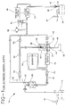
- FIG. 1 is a schematic representation of the fluidics of the present invention, flow cytometer control system, generally denoted by the numeral 10 .
- System pressure or vacuum is developed by a vacuum pump 12 , which draws sheath fluid from a supply reservoir 14 through a flow cell assembly 16 where cell sample is introduced and cell analysis occurs. Waste effluent is then discharged into a waste reservoir 18 .
- the sheath fluid from supply reservoir 14 is purified before entering flow cell assembly 16 by drawing it through a 0.45 micron saline filter 20 .
- a manual tubing pinch valve 22 provided in an outlet passage of the saline filter 20 , is opened to bleed off air trapped in the saline filter 20 .
- a KNF Neuberger Pump Model NF30KVDC is selected for use as vacuum pump 12 because it is self priming and because an identical pump can be used as pressure pump 76 which drives the deaerator 34 thus minimizing the number of components needed in stock to manufacture the invention.
- Flow cell assembly 16 includes an intake passage 24 and first and second outlet passages 26 and 28 , respectively. Within the flow cell assembly 16 , sheath fluid is focused through a cell analysis region 30 . A test sample containing objects, usually tens of thousands of blood cells, is analyzed by counting or sorting the cells at high speeds based on a variety of chemical and physical characteristics such as size, granulation of the cytoplasm and the presence of specific antigens.
- the vacuum level of the flow cytometer control system 10 is regulated to a fixed value by modulating the power delivered to the motor of the vacuum pump 12 based upon the system vacuum level sensed by a vacuum sensor 32 which is connected to the first and second outlet passages, 26 and 28 , of the flow cell assembly 16 .
- Pulsations in vacuum level are attenuated by a pulsation damper 34 which can be a jar with an internal volume many times (10 to 1000 times) the stroke volume of the vacuum pump which is preferably a piston type with inlet and outlet check valves.
- Normally closed vacuum pump discharge pressure switch 36 for example Air Logic Switch Model F4100-100-50W, is connected in series with the motor of vacuum pump 12 to prevent excessive pump discharge pressure which could cause leaks or damage to vacuum pump 12 .
- Pressure switch 36 shuts off the vacuum pump 12 when the waste reservoir 18 is removed.
- the quick disconnect device 38 seals off the flow cytometer control system 10 when the waste reservoir 18 is removed.
- Vent filters 40 for example 0.2 micron TEFLON filters, are provided on the supply reservoir 14 and on the waste reservoir 18 to contain aerosols and prevent fluid spillage when the reservoirs 14 and 18 are handled outside of the instrument.
- a remote discharge connection 42 may replace the waste reservoir 18 , eliminating the need for the operator to handle hazardous waste fluid containers.
- sheath fluid supply reservoir 14 is not pressurized allowing a simple, inexpensive design without pressurized connections or other features which are required to provide a positive system pressure.
- the supply reservoir 14 can also be refilled by gravity drain from a superior supply vessel and waste sheath fluid may be discharged to a remotely located disposal site without affecting the operation of the system.
- the remote discharge feature eliminates the need for the operator to empty the waste reservoir 18 which may expose the operator to bio-hazardous material.
- system leaks do not produce sprays of sheath fluid which can damage optical, electronic, or other components of the test instrument.
- the cell sample is drawn into the flow cell assembly 16 through a sample uptake tube 44 .
- the cell sample vessel 46 is placed in a tube lifter 48 which is raised toward the flow cell assembly 16 until the sample uptake tube 44 is immersed in the sample contained within cell sample vessel 46 .
- a flow resistor 50 which may comprise a piece of conduit of a fixed length with a reduced inside diameter or a needle valve, creates a pressure drop in the conduit leading to flow cell assembly 16 thereby developing a vacuum proximate to the flow cell assembly 16 which aspirates the sample from the cell sample vessel 46 , usually an test tube or cuvette, into the flow cell assembly 16 at the proper rate.
- vacuum driven fluidics proves advantageous in that dripping of the sheath fluid from the sample uptake tube 44 (which could produce bio-hazardous conditions) is avoided. Therefore, auxiliary devices to contain the drip from the sample uptake tube 44 after a test run are not required.
- cell sample vessels do not have to be pressurized or to sealably engage the flow cell assembly 16 thereby allowing freedom of design in terms of the size and shape of the cell sample vessel 46 and freedom of choice in terms of designing a means for cell sample presentation.
- the deaerator 34 is length of thin walled silicone rubber tubing.
- the sheath fluid flows inside the tubing while the outside of the tubing is exposed to the full system vacuum level. Because silicone rubber is permeable to the passage of air, with its major components of oxygen and nitrogen, these gases diffuse through the silicone rubber tubing and are drawn off by the system vacuum.
- a length of silicone rubber tubing is coiled up inside a 4 oz plastic jar. The system vacuum is applied to the jar interior which then also serves as the pulsation damper 34 .
- the tubing is medical grade Dow Corning tubing with 0.132 inch inside diameter, 0.183 outside diameter and a length of 50 inches. Tested at a system vacuum of 0.3 of an atmosphere, this tubing has twice the needed capacity to deaerate the sheath fluid so that no bubbles are formed in the flow cell inlet regions.
- the tube lifter 48 is a linear motion device which travels from a bottom position, where the cell sample vessel 46 is installed or removed conveniently by the operator, to an upward position over a distance of about five inches. In the upward position, the tube lifter 48 presents the cell sample vessel 46 to the sample uptake tube 44 through which the cell sample is aspirated from the cell sample vessel 46 into the flow cell assembly 16 .
- the tube lifter 48 is guided on a rod during its linear travel and is driven upward and downward by a small DC motor operating through a gear train with a rack and pinion to produce the linear motion.
- opto-interruptive devices which sense the interruption of an optical beam by a sheet metal flag on the carriage of the tube lifter 48 when the tube lifter 48 has traveled to the top or bottom position. These sensing devices are positioned at both the top and bottom positions which causes the power to the motor of tube lifter 48 to be shut off.
- the carriage of tube lifter 48 remains in the down position by gravity when no voltage is applied to the motor of tube lifter 48 .
- the carriage of tube lifter 48 is held in the upward position by a retaining magnet.
- V1-V4, 52 , 54 , 56 , 58 are connected to the flow cell assembly 16 to provide control of fluid flow.
- V1 is connected to the intake passage 24 of flow cell assembly 16 .
- V2 54 is connected to the first outlet passage 26 of the flow cell assembly 16 and to the vacuum pump 12 providing communication between the flow cell assembly 16 and the waste reservoir 18 .
- V3 56 also connected to the first outlet passage 26 , vents to atmospheric pressure.
- V4 58 is connected to the second outlet passage 28 of flow cell assembly 16 providing a communication path through the flow cell assembly 16 to waste reservoir 18 .
- FIG. 2 is a schematic representation of the computer control system for the flow cytometer control system.
- the computer control system 60 includes microprocessor unit 62 comprises a single circuit board mounted inside the instrument cabinet of the flow cytometer control system 10 .
- Operator access switches 64-68 actuate RUN, STOP (STANDBY) and DRAIN test modes, respectively.
- the micro-processor unit 62 for example Intel 286, may also be used for automatic control.
- STOP (STANDBY) mode all the valves V1-V4 52 , 54 , 56 , 58 are closed.
- V1 52 and V2 54 are open permitting sheath fluid to flow through the flow cell assembly 16 .
- Valves V3 56 and V4 58 are opened by actuating the DRAIN operator access switch 68 to provide an alternative communication path through the cell analysis region 30 of the flow cell assembly 16 to waste reservoir 18 .
- the flow cell assembly 16 is drained to clear clogs and remove gas bubbles trapped in the flow cell assembly 16 . Opening valves V3 56 and V4 58 allows air to enter the flow cell and fluid to exit through valve V4 58 .
- An air flow restrictor 50 with a protective filter is provided between valve V3 56 and the atmospheric inlet to limit airflow during the DRAIN mode to a value less than the vacuum pump capacity so that the system vacuum or pressure level can be maintained.
- Computer control allows valve actuation timing, tube lifter ascent and descent timing and reverse flush pump timing to be specified in computer programs which are downloaded into the micro-processor unit 62 from the storage medium 72 .
- the storage medium 72 may be provided, for example, by a floppy disk inserted into a floppy disk drive 74 which is also contained in the computer control system 60 .
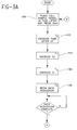
- FIGS. 3A and 3B are a flow diagram depicting the method steps for computer program control of the present invention, the flow cytometer control system including valves V1-V4 52-58 , the reverse or back-flush pressure pump 76 , and the tube lifter 48 .
- FIG 4 is a timing diagram depicting the energized states of these components during normal test RUN cycle.
- the method of the present invention begins in step 100 by placing a new sample contained in a cell sample vessel 46 into the tube lifter 48 and the RUN switch 64 is actuated by the operator.
- step 102 the tube lifter up (TLU) line 47 is energized causing the tube lifter 48 to be driven upward for 59 computer ticks (each computer tick is equal to 18 seconds) or approximately 3 seconds. This completes the upward ascent of the tube lifter.
- the tube lifter is maintained in the up position by a retaining magnet.
- step 104 while the tube lifter 48 is maintained in the up position, valve V2 54 is energized or opened for 18 computer ticks or one second to perform the auto-boost function wherein the cell sample is aspirated from the cell sample vessel 46 at 5 to 7 times the normal rate to boost the cell sample flow rate through the analysis region 30 to the normal test level more rapidly.
- step 106 valve V1 52 is energized for 126 computer ticks or 7 seconds, while the tube lifter is maintained in its upward position and V2 54 remains open.
- step 108 data acquisition begins in step 108 for whatever period is necessary for the particular test being run while V1 52 and V2 54 remain energized and the tube lifter 48 is maintained in its up position.
- the data acquisition period of step 108 includes a period for the system to reach full stabilization of the sheath and sample flows, for example seven seconds.
- step 112 valves V1 52 and V2 54 are each maintained in the energized or open position, the tube lifter 48 is maintained in its upward position while the reverse flush pump 76 is energized to perform the reverse flush cycle for 36 computer ticks or 2 seconds.
- step 114 for the next 2 computer ticks or just 0.1 seconds, while valves V1 52 and V2 54 are still energized or open, the tube lifter down line 49 is energized to begin the descent of the tube lifter 48 .
- the tube lifter down (TLD) line causes the tube lifter 48 to be driven downward.
- step 116 the tube lifter down line 49 is deenergized while valves V1 52 and V2 54 are still maintained in an energized or open condition for 54 computer ticks or 3 seconds. During this time, the tube lifter 48 continues a slow descent begun in the previous step 114 in which the tube lifter line 48 was energized for just 0.1 second. The slow descent of the tube lifter 48 allows the cell sample vessel 46 to slowly separate from the cell sample uptake tube 44 and the residual cell sample to drain from the cell sample uptake tube 44 back into the descending cell sample vessel 46 .
- valves V1 52 and V2 54 are deenergized or closed while valve V3 56 , the atmospheric inlet valve, is energized or opened and the tube lifter down line 49 is energized for 54 computer ticks or 3 seconds driving the tube lifter 48 downward.
- Operational amplifier 80 accepts input signals from vacuum sensor 32 , connected to the inlet of pulsation damper 34 .
- Vacuum sensor 32 monitors the over-all system vacuum or pressure level.
- the vacuum sensor 32 incorporates a diaphragm of a piezoresistive material which generates a proportional voltage when deflected in response to the system pressure or vacuum level.
- the output from vacuum sensor 32 is modeled in the form of a Wheatstone Bridge which is energized at terminals 1 and 3 from a 12V power source 78 .
- the Wheatstone bridge is picked up on balance from terminals 2 and 4 and applied to the terminals of operational amplifier 80 , which has a feedback resistor 82 of 100K Ohms.
- the output of operational amplifier 82 at pin 1 is a voltage which has a proportional linear relationship to the system pressure or vacuum level (voltage/pressure).
- the output of the operational amplifier 80 is applied to the positive input terminal of operational amplifier 84 .
- Potentiometer 86 ranges from a positive 12V setting to a zero voltage setting and acts as the vacuum setting level control which is applied to the negative input terminal of operational amplifier 84 .
- Operational amplifier 84 acts as a comparator to determine which input voltage is greater.
- the current from operational amplifier 84 drives motor driver 70 (Power MOSFET), to output more current to the motor of vacuum pump 12 to drive it faster and harder in an effort to bring the system vacuum level up to the data level set by the potentiometer 86 .
- This scheme provides utilization of the full drive voltage (to within a few tenths of a volt) from the motor of vacuum pump 12 .
- the "no load” to "full load” ratio provide has been found to be within approximately 3% of the vacuum setting.
- the vacuum level is set to approximately 4.5 psi vacuum below atmospheric pressure at the factory.
- the discharge pressure switch 36 is normally closed. If there is no pressure at the discharge of the vacuum pump 12 then discharge pressure switch 36 remains closed and the vacuum pump control circuit functions normally. If excessive pressure builds up at the discharge conduit of the vacuum pump 12 , then discharge pressure switch 36 opens the circuit, disconnecting power from the vacuum pump 12 . Such an excessive pressure condition may occur when then the waste reservoir 18 is removed. In this event, quick disconnect device 38 seals off the conduit so that the system begins to output effluent into a dead-end passage thereby building up pressure. Provision of discharge pressure switch 36 prevents the motor of vacuum pump 12 from burning out or from spraying effluent saline solution into the environment.
- Vacuum sensor 32 may be provided by Motorola Vacuum Sensor Model MPX2051.
- Motor driver 70 is provided, for example, by Power MOSFET Model 1RF513
- One advantage of regulating power delivery to the motor of vacuum pump 12 based on a preselected system vacuum level is that the vacuum pump 12 runs only when required as a "demand" component. Thus, the vacuum pump 12 need not run at all during instrument STANDBY mode when no sheath fluid flows and may run only a few percent of the rated speed during normal test RUN mode thereby extending the life of the vacuum pump 12 .
- the identical pump model is utilized as both the vacuum pump 12 and the pressure pump 76 . This pump may be provided, for example by KNF Neuberger, Model NF30KVDC.
- this pump is self priming.
- the pump When the system is first energized, the pump must be able to pull air through the system conduits followed some seconds later by pulling liquid to create the normal vacuum cycle. To perform this function, the vacuum pump must be "self-priming.”
- the pump when used as pressure pump 76 , it must be able to flow the sheath fluid when in a non-energized state and must thus have a low pressure drop.
- the aforementioned model pump has very small pressure drop check valves which allow the fluid to be pulled through the pump without a great pressure drop.
Landscapes
- Chemical & Material Sciences (AREA)
- Dispersion Chemistry (AREA)
- Physics & Mathematics (AREA)
- Health & Medical Sciences (AREA)
- Life Sciences & Earth Sciences (AREA)
- Analytical Chemistry (AREA)
- Biochemistry (AREA)
- General Health & Medical Sciences (AREA)
- General Physics & Mathematics (AREA)
- Immunology (AREA)
- Pathology (AREA)
- Investigating Or Analysing Biological Materials (AREA)
- Apparatus Associated With Microorganisms And Enzymes (AREA)
- Sampling And Sample Adjustment (AREA)
Applications Claiming Priority (4)
| Application Number | Priority Date | Filing Date | Title |
|---|---|---|---|
| US98962292A | 1992-12-14 | 1992-12-14 | |
| US19716 | 1993-02-19 | ||
| US08/019,716 US5395588A (en) | 1992-12-14 | 1993-02-19 | Control of flow cytometer having vacuum fluidics |
| US989622 | 1993-02-19 |
Publications (2)
| Publication Number | Publication Date |
|---|---|
| EP0602416A1 true EP0602416A1 (de) | 1994-06-22 |
| EP0602416B1 EP0602416B1 (de) | 1999-03-03 |
Family
ID=26692525
Family Applications (1)
| Application Number | Title | Priority Date | Filing Date |
|---|---|---|---|
| EP93118851A Expired - Lifetime EP0602416B1 (de) | 1992-12-14 | 1993-11-24 | Durchflusszytometer mit vakuumgesteuerter Strömung |
Country Status (5)
| Country | Link |
|---|---|
| US (1) | US5395588A (de) |
| EP (1) | EP0602416B1 (de) |
| JP (1) | JP2525123B2 (de) |
| CA (1) | CA2110113C (de) |
| DE (1) | DE69323700T2 (de) |
Cited By (15)
| Publication number | Priority date | Publication date | Assignee | Title |
|---|---|---|---|---|
| EP0753348A1 (de) * | 1995-07-10 | 1997-01-15 | Yazaki Corporation | Vorrichtung zur Sortierung von Materialien durch Sedimentation |
| FR2777350A1 (fr) * | 1998-04-08 | 1999-10-15 | Hycel Diagnostics | Dispositif de mesure assurant la maintenance automatique de l'optique de collection d'une tete cytometrique |
| WO1999046047A3 (en) * | 1998-03-10 | 1999-12-02 | Biosource Proteomics Inc | Detection and characterization of microorganisms |
| WO2004030725A1 (en) * | 2002-09-30 | 2004-04-15 | Bausch & Lomb Incorporated | Aspiration flow resistor |
| EP1664738A1 (de) * | 2003-09-19 | 2006-06-07 | Hydac Filtertechnik GmbH | Vorrichtung zur partikelmessung |
| CN101111756B (zh) * | 2004-12-03 | 2011-01-19 | Xy公司 | 用于流体输送的压力调节的连续可变容积容器 |
| US8597573B2 (en) | 2009-06-05 | 2013-12-03 | Xy, Llc | Continuously regulated precision pressure fluid delivery system |
| EP1991863A4 (de) * | 2006-03-08 | 2014-01-29 | Accuri Instr Inc | Fluidisches system für ein fluss-zytometer |
| CN104280328A (zh) * | 2014-06-20 | 2015-01-14 | 博奥生物集团有限公司 | 一种流式细胞分析装置及分析方法 |
| US9739699B2 (en) | 2007-11-15 | 2017-08-22 | Seng Enterprises Ltd. | Device for the study of living cells |
| US9975118B2 (en) | 2007-11-15 | 2018-05-22 | Seng Enterprises Ltd. | Device for the study of living cells |
| US10031064B2 (en) | 2010-10-25 | 2018-07-24 | Accuri Cytometers, Inc. | Systems and user interface for collecting a data set in a flow cytometer |
| US10190082B2 (en) | 2003-06-26 | 2019-01-29 | Seng Enterprises Ltd. | Multiwell plate |
| DE102017008580A1 (de) * | 2017-09-13 | 2019-03-14 | Hydac Filter Sytems Gmbh | Filteraggregat |
| GB2583765A (en) * | 2019-05-10 | 2020-11-11 | Alphasense Ltd | Filter unit for an opitcal particle counter |
Families Citing this family (129)
| Publication number | Priority date | Publication date | Assignee | Title |
|---|---|---|---|---|
| WO1995035492A2 (de) * | 1994-06-17 | 1995-12-28 | Evotec Biosystems Gmbh | Verfahren und vorrichtung zur gezielten entnahme von komponenten aus komplexen mischungen |
| US5833925A (en) * | 1996-11-13 | 1998-11-10 | Beckman Instruments, Inc. | Automatic chemistry analyzer with improved ion selective electrode assembly |
| JP4323571B2 (ja) | 1997-01-31 | 2009-09-02 | エックスワイ, インコーポレイテッド | 光学装置 |
| AU8497398A (en) * | 1997-07-17 | 1999-02-10 | Regents Of The University Of California, The | Collapsible sheath fluid reservoirs for flow cytometers |
| US5895764A (en) * | 1997-11-24 | 1999-04-20 | University Of New Mexico | Controlled sheath flow injection cytometry |
| US6149867A (en) * | 1997-12-31 | 2000-11-21 | Xy, Inc. | Sheath fluids and collection systems for sex-specific cytometer sorting of sperm |
| US6071689A (en) * | 1997-12-31 | 2000-06-06 | Xy, Inc. | System for improving yield of sexed embryos in mammals |
| US6110427A (en) * | 1998-08-14 | 2000-08-29 | Becton, Dickinson And Company | Flow regulator to maintain controllable volumetric flow rate |
| US6315952B1 (en) | 1998-10-05 | 2001-11-13 | The University Of New Mexico | Plug flow cytometry for high throughput screening and drug discovery |
| US7416903B2 (en) * | 1999-09-30 | 2008-08-26 | Stc.Unm | Wavy interface mixer |
| US6890487B1 (en) * | 1999-09-30 | 2005-05-10 | Science & Technology Corporation ©UNM | Flow cytometry for high throughput screening |
| US7208265B1 (en) * | 1999-11-24 | 2007-04-24 | Xy, Inc. | Method of cryopreserving selected sperm cells |
| AU2001243295A1 (en) * | 2000-02-10 | 2001-08-20 | The University Of New Mexico | Flow cytometry for high throughput screening |
| IL136232A0 (en) * | 2000-05-18 | 2001-05-20 | Bar Ilan University Res Author | Measurements of enzymatic activity in a single, individual cell in population |
| JP3665257B2 (ja) * | 2000-07-11 | 2005-06-29 | 株式会社日立製作所 | 分注装置 |
| US20040031071A1 (en) * | 2000-10-05 | 2004-02-12 | Xy, Inc. | System of hysteroscopic insemination of mares |
| CA2822983C (en) | 2000-11-29 | 2017-05-09 | Xy, Llc | System to separate frozen-thawed spermatozoa into x-chromosome bearing and y-chromosome bearing populations |
| US7713687B2 (en) * | 2000-11-29 | 2010-05-11 | Xy, Inc. | System to separate frozen-thawed spermatozoa into x-chromosome bearing and y-chromosome bearing populations |
| DE60221984T2 (de) | 2001-06-13 | 2008-05-15 | Kenneth F. Los Gatos Uffenheimer | Automatisches flüssigkeitsbehandlungssystem und -verfahren |
| EP2332651A3 (de) * | 2001-10-25 | 2011-08-31 | Bar Ilan University | Interaktiver transparenter Biochip-Prozessor für einzeln adressierbare Zellen |
| US20030175980A1 (en) * | 2002-03-14 | 2003-09-18 | Hayenga Jon W. | Ribbon flow cytometry and cell sorting |
| US7157274B2 (en) * | 2002-06-24 | 2007-01-02 | Cytonome, Inc. | Method and apparatus for sorting particles |
| US9943847B2 (en) | 2002-04-17 | 2018-04-17 | Cytonome/St, Llc | Microfluidic system including a bubble valve for regulating fluid flow through a microchannel |
| US20070065808A1 (en) * | 2002-04-17 | 2007-03-22 | Cytonome, Inc. | Method and apparatus for sorting particles |
| US6976590B2 (en) | 2002-06-24 | 2005-12-20 | Cytonome, Inc. | Method and apparatus for sorting particles |
| US6808075B2 (en) | 2002-04-17 | 2004-10-26 | Cytonome, Inc. | Method and apparatus for sorting particles |
| EP1542529A4 (de) * | 2002-07-22 | 2006-08-09 | Xy Inc | Spermazellenverfahrenssystem |
| US8211629B2 (en) * | 2002-08-01 | 2012-07-03 | Xy, Llc | Low pressure sperm cell separation system |
| US8486618B2 (en) | 2002-08-01 | 2013-07-16 | Xy, Llc | Heterogeneous inseminate system |
| CA2534394C (en) * | 2002-08-15 | 2013-01-08 | Xy, Inc. | High resolution flow cytometer |
| US7169548B2 (en) | 2002-09-13 | 2007-01-30 | Xy, Inc. | Sperm cell processing and preservation systems |
| US7648678B2 (en) * | 2002-12-20 | 2010-01-19 | Dako Denmark A/S | Method and system for pretreatment of tissue slides |
| IL154677A0 (en) * | 2003-02-27 | 2003-09-17 | Univ Bar Ilan | A method and apparatus for manipulating an individual cell |
| DK2959774T3 (da) | 2003-03-28 | 2019-05-13 | Inguran Llc | Fremgangsmåde til kryokonservering af sædceller |
| WO2004104178A2 (en) * | 2003-05-15 | 2004-12-02 | Xy, Inc. | Efficient haploid cell sorting for flow cytometer systems |
| US20050011582A1 (en) * | 2003-06-06 | 2005-01-20 | Haug Jeffrey S. | Fluid delivery system for a flow cytometer |
| US7601545B2 (en) * | 2003-06-20 | 2009-10-13 | Groton Biosystems, Llc | Automated macromolecule sample preparation system |
| US7341652B2 (en) * | 2003-06-20 | 2008-03-11 | Groton Biosytems, Llc | Stationary capillary electrophoresis system |
| US7169599B2 (en) * | 2003-06-20 | 2007-01-30 | Groton Biosystems, Llc | Fluid interface for bioprocessor systems |
| US7888110B2 (en) | 2003-06-26 | 2011-02-15 | Seng Enterprises Ltd. | Pico liter well holding device and method of making the same |
| US8597597B2 (en) | 2003-06-26 | 2013-12-03 | Seng Enterprises Ltd. | Picoliter well holding device and method of making the same |
| WO2004113492A1 (en) * | 2003-06-26 | 2004-12-29 | Molecular Cytomics Ltd. | Improved materials for constructing cell-chips, cell-chip covers, cell-chip coats, processed cell-chips and uses thereof |
| WO2005008626A1 (en) * | 2003-07-11 | 2005-01-27 | University Of North Carolina At Chapel Hill | Methods and systems for controlling a computer using a video image and for combining the video image with a computer desktop |
| US20050064524A1 (en) * | 2003-08-11 | 2005-03-24 | Mordechai Deutsch | Population of cells utilizable for substance detection and methods and devices using same |
| BRPI0506610A (pt) * | 2004-02-03 | 2007-05-02 | Chemagis Ltd | montelucaste sódico amorfo, processo de preparação de montelucaste sódico amorfo, composição farmacêutica, método de tratamento utilizando a administração de montelucaste sódico amorfo, co-precipitado amorfo de montelucaste sódico e processo de preparação de co-precipitado amorfo de montelucaste sódico |
| EP2260854A1 (de) | 2004-03-29 | 2010-12-15 | Inguran, LLC | Spermasuspensionen zur Sortierung in X- oder Y-Chromosomen-tragende angereicherte Populationen |
| US7403647B2 (en) * | 2004-09-13 | 2008-07-22 | Seng Enterprises Ltd. | Method for identifying an image of a well in an image of a well-bearing component |
| US20080063251A1 (en) * | 2004-07-07 | 2008-03-13 | Mordechai Deutsch | Method and Device for Identifying an Image of a Well in an Image of a Well-Bearing |
| US20060012793A1 (en) * | 2004-07-19 | 2006-01-19 | Helicos Biosciences Corporation | Apparatus and methods for analyzing samples |
| US7276720B2 (en) | 2004-07-19 | 2007-10-02 | Helicos Biosciences Corporation | Apparatus and methods for analyzing samples |
| AU2005266930B2 (en) | 2004-07-22 | 2010-09-16 | Inguran, Llc | Process for enriching a population of sperm cells |
| US7340957B2 (en) | 2004-07-29 | 2008-03-11 | Los Alamos National Security, Llc | Ultrasonic analyte concentration and application in flow cytometry |
| WO2006021959A2 (en) * | 2004-08-25 | 2006-03-02 | Seng Enterprises Ltd. | Method and device for isolating cells |
| US20070070349A1 (en) * | 2005-09-23 | 2007-03-29 | Helicos Biosciences Corporation | Optical train and method for TIRF single molecule detection and analysis |
| US9260693B2 (en) | 2004-12-03 | 2016-02-16 | Cytonome/St, Llc | Actuation of parallel microfluidic arrays |
| DE602005023534D1 (de) * | 2005-01-25 | 2010-10-21 | Seng Entpr Ltd | Mikrofluidische vorrichtung zur untersuchung zellen |
| US20060286566A1 (en) * | 2005-02-03 | 2006-12-21 | Helicos Biosciences Corporation | Detecting apparent mutations in nucleic acid sequences |
| DE102005034043B4 (de) * | 2005-07-18 | 2019-12-12 | Südzucker Aktiengesellschaft Mannheim/Ochsenfurt | Gemisch, enthaltend L-Carnitin und Trehalulose, sowie Produkt enthaltend das Gemisch |
| US7996188B2 (en) | 2005-08-22 | 2011-08-09 | Accuri Cytometers, Inc. | User interface for a flow cytometer system |
| US20070141555A1 (en) * | 2005-10-11 | 2007-06-21 | Mordechai Deutsch | Current damper for the study of cells |
| US7776268B2 (en) * | 2005-10-13 | 2010-08-17 | Accuri Cytometers, Inc. | User interface for a fluidic system of a flow cytometer |
| US8303894B2 (en) * | 2005-10-13 | 2012-11-06 | Accuri Cytometers, Inc. | Detection and fluidic system of a flow cytometer |
| WO2007052245A1 (en) * | 2005-11-03 | 2007-05-10 | Seng Enterprises Ltd. | Method and device for studying floating, living cells |
| US7328722B2 (en) * | 2005-12-07 | 2008-02-12 | Accuri Cytometers, Inc. | Pulsation attenuator for a fluidic system |
| US7857005B2 (en) * | 2005-12-07 | 2010-12-28 | Accuri Cytometers, Inc. | Pulsation attenuator for a fluidic system |
| US8283177B2 (en) * | 2006-03-08 | 2012-10-09 | Accuri Cytometers, Inc. | Fluidic system with washing capabilities for a flow cytometer |
| US7780916B2 (en) * | 2006-03-08 | 2010-08-24 | Accuri Cytometers, Inc. | Flow cytometer system with unclogging feature |
| US20070224684A1 (en) * | 2006-03-22 | 2007-09-27 | Olson David C | Transportable flow cytometer |
| US7981661B2 (en) * | 2006-04-17 | 2011-07-19 | Accuri Cytometers, Inc. | Flow cytometer system with sheath and waste fluid measurement |
| US20060223999A1 (en) * | 2006-05-10 | 2006-10-05 | Chemagis Ltd. | Process for preparing montelukast and precursors thereof |
| US8715573B2 (en) * | 2006-10-13 | 2014-05-06 | Accuri Cytometers, Inc. | Fluidic system for a flow cytometer with temporal processing |
| US7835000B2 (en) | 2006-11-03 | 2010-11-16 | Los Alamos National Security, Llc | System and method for measuring particles in a sample stream of a flow cytometer or the like |
| WO2008058217A2 (en) * | 2006-11-07 | 2008-05-15 | Accuri Instruments Inc. | Flow cell for a flow cytometer system |
| US7739060B2 (en) * | 2006-12-22 | 2010-06-15 | Accuri Cytometers, Inc. | Detection system and user interface for a flow cytometer system |
| EP2479552B1 (de) * | 2007-04-02 | 2015-09-02 | Acoustic Cytometry Systems, Inc. | Verfahren zur verbesserten Analyse von in einem akustischen Feld fokussierten Zellen und Partikeln |
| US7837040B2 (en) * | 2007-04-09 | 2010-11-23 | Los Alamos National Security, Llc | Acoustic concentration of particles in fluid flow |
| US8083068B2 (en) | 2007-04-09 | 2011-12-27 | Los Alamos National Security, Llc | Apparatus for separating particles utilizing engineered acoustic contrast capture particles |
| US8528406B2 (en) * | 2007-10-24 | 2013-09-10 | Los Alamos National Security, LLP | Method for non-contact particle manipulation and control of particle spacing along an axis |
| US8263407B2 (en) | 2007-10-24 | 2012-09-11 | Los Alamos National Security, Llc | Method for non-contact particle manipulation and control of particle spacing along an axis |
| US8432541B2 (en) * | 2007-12-17 | 2013-04-30 | Accuri Cytometers, Inc. | Optical system for a flow cytometer with an interrogation zone |
| US8266951B2 (en) * | 2007-12-19 | 2012-09-18 | Los Alamos National Security, Llc | Particle analysis in an acoustic cytometer |
| AU2013205061B9 (en) * | 2007-12-19 | 2015-02-19 | Los Alamos National Security, Llc | Particle analysis in an acoustic cytometer |
| US8714014B2 (en) * | 2008-01-16 | 2014-05-06 | Life Technologies Corporation | System and method for acoustic focusing hardware and implementations |
| US20090253163A1 (en) * | 2008-04-02 | 2009-10-08 | General Electric Company | Iterative staining of biological samples |
| US20100043883A1 (en) * | 2008-06-25 | 2010-02-25 | Groton Biosystems, Llc | System and method for automated sterile sampling of fluid from a vessel |
| US8373858B2 (en) * | 2008-12-10 | 2013-02-12 | Livermore Instruments, Inc. | System and method for real time determination of size and chemical composition of aerosol particles |
| DE102008062477B3 (de) * | 2008-12-16 | 2010-03-25 | Airbus Deutschland Gmbh | Verfahren, System und Formwerkzeug zum Herstellen von Bauteilen aus Faserverbundwerkstoffen |
| WO2010132053A1 (en) | 2009-05-13 | 2010-11-18 | Indevr, Inc. | Flow measurement and control for improved quantification of particles in flow cytometry |
| WO2010135627A1 (en) | 2009-05-21 | 2010-11-25 | Intellicyt | System and method for separating samples in a continuous flow |
| US8507279B2 (en) * | 2009-06-02 | 2013-08-13 | Accuri Cytometers, Inc. | System and method of verification of a prepared sample for a flow cytometer |
| US20110061471A1 (en) * | 2009-06-02 | 2011-03-17 | Rich Collin A | System and method of verification of a sample for a flow cytometer |
| US9752964B1 (en) | 2009-06-22 | 2017-09-05 | Stc.Unm | Flow cytometry apparatus pulling sample stream through observation chamber |
| US8589851B2 (en) * | 2009-12-15 | 2013-11-19 | Memoir Systems, Inc. | Intelligent memory system compiler |
| JP2011145162A (ja) * | 2010-01-14 | 2011-07-28 | Japan Atomic Energy Agency | 流体中微粒子のx線検出法 |
| WO2011106402A1 (en) * | 2010-02-23 | 2011-09-01 | Accuri Cytometers, Inc. | Method and system for detecting fluorochromes in a flow cytometer |
| US9551600B2 (en) | 2010-06-14 | 2017-01-24 | Accuri Cytometers, Inc. | System and method for creating a flow cytometer network |
| US8528427B2 (en) | 2010-10-29 | 2013-09-10 | Becton, Dickinson And Company | Dual feedback vacuum fluidics for a flow-type particle analyzer |
| US20120125126A1 (en) | 2010-11-19 | 2012-05-24 | Becton, Dickinson And Company | Fluidics with thermal compensation for a flow-type particle analyzer |
| CN102564918B (zh) * | 2010-12-31 | 2015-12-02 | 深圳迈瑞生物医疗电子股份有限公司 | 粒子计数装置和血液细胞分析装置 |
| JP2012237557A (ja) * | 2011-05-09 | 2012-12-06 | Shimadzu Corp | 液体試料採取装置及び液体試料採取方法 |
| JP2012251881A (ja) * | 2011-06-03 | 2012-12-20 | Bay Bioscience Kk | 液体フローに含まれる生物学的粒子を分析するシステム |
| US9551637B2 (en) * | 2012-06-14 | 2017-01-24 | Bio-Rad Laboratories, Inc. | Flow rate balanced, dynamically adjustable sheath delivery system for flow cytometry |
| CN104487819B (zh) * | 2012-06-22 | 2017-10-27 | 生物辐射实验室股份有限公司 | 两站式样本及洗涤系统 |
| CN103575633B (zh) | 2012-08-10 | 2017-11-17 | 深圳迈瑞生物医疗电子股份有限公司 | 一种流式仪器及其液路系统 |
| DE102012108989B3 (de) | 2012-09-24 | 2014-01-23 | Eads Deutschland Gmbh | Detektionsvorrichtung sowie Verfahren zur automatischen Detektion von Partikeln |
| EP2906928A4 (de) | 2012-10-15 | 2016-11-09 | Nanocellect Biomedical Inc | Systeme, vorrichtungen und verfahren zum sortieren von partikeln |
| JP2016503507A (ja) * | 2012-11-29 | 2016-02-04 | サイトフロー・リミテッド・ライアビリティ・カンパニーCytoFlow, LLC | 流体システムおよび方法 |
| CN103353513B (zh) * | 2013-07-12 | 2015-12-23 | 肖巍 | 一种基于单元计量的液路系统及其使用方法 |
| CN104127192B (zh) * | 2013-10-16 | 2016-08-10 | 深圳市帝迈生物技术有限公司 | 一种流式细胞仪流体系统及流式细胞检测方法 |
| US9551644B2 (en) * | 2014-07-11 | 2017-01-24 | Intellicyt | Methods and apparatus for real-time detection and clearing of a clog |
| WO2016100954A1 (en) | 2014-12-19 | 2016-06-23 | Captl Llc | Flow cytometry using hydrodynamically planar flow |
| WO2016099538A1 (en) | 2014-12-19 | 2016-06-23 | Captl Llc | Flow cytometry using hydrodynamically planar flow |
| US10241024B1 (en) * | 2016-05-02 | 2019-03-26 | Rashid Mavliev | System and method for characterization of inclusions in liquid samples |
| KR102106384B1 (ko) | 2016-06-07 | 2020-05-06 | 에센 인스트루먼츠, 인크. 디/비/에이/ 에센 바이오사이언스, 인크. | 유세포 분석 산란 파형 분석을 사용하여 샘플들 사이의 기포 검출을 위한 방법 |
| CN106053321A (zh) * | 2016-08-10 | 2016-10-26 | 成都索尔恩科技有限公司 | 一种用于流式细胞术的液流系统 |
| US11982611B2 (en) | 2017-03-20 | 2024-05-14 | Nanocellect Biomedical, Inc. | Systems, apparatuses, and methods for cell sorting and flow cytometry |
| JP7078034B2 (ja) * | 2017-03-31 | 2022-05-31 | ソニーグループ株式会社 | 流路ユニット及び微小粒子分析装置 |
| ES2967515T3 (es) | 2018-08-01 | 2024-04-30 | Sartorius Bioanalytical Instr Inc | Métodos, kits y composiciones de tinción para la evaluación de citometría de flujo de partículas del tamaño de un virus no asociadas utilizando múltiples colorantes fluorogénicos |
| CN112823275B (zh) * | 2018-08-15 | 2024-09-17 | 贝克顿·迪金森公司 | 适用于流式颗粒分析仪的流量和真空受控流体管理系统 |
| CN109061214B (zh) * | 2018-10-31 | 2023-12-19 | 江苏卓微生物科技有限公司 | 多孔进样装置 |
| WO2020118255A1 (en) * | 2018-12-07 | 2020-06-11 | Element Biosciences, Inc. | Flow cell device and use thereof |
| US11137337B2 (en) | 2019-01-21 | 2021-10-05 | Essen Instruments, Inc. | Flow cytometry with data analysis for optimized dilution of fluid samples for flow cytometry investigation |
| WO2020197644A1 (en) | 2019-03-26 | 2020-10-01 | Essen Instruments, Inc. D/B/A Essen Bioscience, Inc. | Flow cytometry evaluation for unassociated non-enveloped viral particles |
| JP7549647B2 (ja) | 2019-08-19 | 2024-09-11 | ザルトリウス バイオアナリティカル インストゥルメンツ, インコーポレイテッド | サンプル間の分離ガス検出のためのシステムおよび方法 |
| US11709116B2 (en) | 2020-02-04 | 2023-07-25 | Sartorius Bioanalytical Instruments, Inc. | Liquid flourescent dye concentrate for flow cytometry evaluation of virus-size particles and related products and methods |
| WO2022225597A1 (en) * | 2021-04-23 | 2022-10-27 | Becton, Dickinson And Company | Fluid management system for an analyzer and/or sorter type flow type particle analyzer |
| GB2629259B (en) | 2021-07-21 | 2025-05-28 | Element Biosciences Inc | Optical systems for nucleic acid sequencing and methods thereof |
| EP4537076A4 (de) * | 2022-06-06 | 2025-07-23 | Becton Dickinson Co | Strömungswiderstandseinheiten sowie durchflusszytometer und verfahren damit |
| CN119959111B (zh) * | 2025-04-09 | 2025-07-01 | 泛肽生物科技(浙江)有限公司 | 一种流式细胞仪及其取液方法、系统和存储介质 |
Citations (2)
| Publication number | Priority date | Publication date | Assignee | Title |
|---|---|---|---|---|
| JPH0436636A (ja) * | 1990-06-01 | 1992-02-06 | Canon Inc | フローセル装置 |
| EP0478392A2 (de) * | 1990-09-28 | 1992-04-01 | Toa Medical Electronics Co., Ltd. | Teilchenanalysator und Druchflusszelle dafür |
Family Cites Families (18)
| Publication number | Priority date | Publication date | Assignee | Title |
|---|---|---|---|---|
| US2656508A (en) * | 1949-08-27 | 1953-10-20 | Wallace H Coulter | Means for counting particles suspended in a fluid |
| BE562451A (de) * | 1956-05-09 | |||
| US3810010A (en) * | 1968-11-02 | 1974-05-07 | Telefunken Patent | Particle analysis method and apparatus wherein liquid containing particles is sucked into a constricted flow path |
| US3793589A (en) * | 1972-06-28 | 1974-02-19 | Gen Electric | Data communication transmitter utilizing vector waveform generation |
| US3960020A (en) * | 1974-12-30 | 1976-06-01 | Technicon Instruments Corporation | Liquid aspirating probe assembly of a supply analyzer |
| DE2656654C3 (de) * | 1976-12-14 | 1981-02-12 | Max-Planck-Gesellschaft Zur Foerderung Der Wissenschaftense.V., 3400 Goettingen | Vorrichtung zur Messung des Volumens und bestimmter optischer Eigenschaften von Partikeln |
| DE2716095C2 (de) * | 1977-04-12 | 1987-02-19 | Becton, Dickinson and Co., Paramus, N.J. | Verfahren zur Steuerung der Bewegungsbahn von in einem Elektrolyten suspendierten Teilchen und Vorrichtung zur Durchführung dieses Verfahrens |
| US4230558A (en) * | 1978-10-02 | 1980-10-28 | Coulter Electronics, Inc. | Single drop separator |
| US4318885A (en) * | 1979-09-10 | 1982-03-09 | Olympus Optical Co., Ltd. | Liquid treating device for chemical analysis apparatus |
| US4478095A (en) * | 1981-03-09 | 1984-10-23 | Spectra-Physics, Inc. | Autosampler mechanism |
| US4673288A (en) * | 1981-05-15 | 1987-06-16 | Ratcom, Inc. | Flow cytometry |
| DE3266669D1 (en) * | 1981-06-24 | 1985-11-07 | Becton Dickinson Co | Analyzer for simultaneously determining volume and light emission characteristics of particles |
| EP0177718B1 (de) * | 1984-09-11 | 1989-12-06 | Partec AG | Verfahren und Vorrichtung zur Sortierung von mikroskopischen Partikeln |
| US4713974A (en) * | 1986-04-18 | 1987-12-22 | Varian Associates, Inc./Scientific Systems, Inc. | Autosampler |
| US5040890A (en) * | 1987-11-25 | 1991-08-20 | Becton, Dickinson And Company | Sheathed particle flow controlled by differential pressure |
| US4844610A (en) * | 1988-04-29 | 1989-07-04 | Becton, Dickinson And Company | Backflow isolator and capture system |
| US5030002A (en) * | 1989-08-11 | 1991-07-09 | Becton, Dickinson And Company | Method and apparatus for sorting particles with a moving catcher tube |
| JPH081484Y2 (ja) * | 1990-07-05 | 1996-01-17 | 日本酸素株式会社 | パーティクルカウンター |
-
1993
- 1993-02-19 US US08/019,716 patent/US5395588A/en not_active Expired - Lifetime
- 1993-11-24 EP EP93118851A patent/EP0602416B1/de not_active Expired - Lifetime
- 1993-11-24 DE DE69323700T patent/DE69323700T2/de not_active Expired - Lifetime
- 1993-11-26 CA CA002110113A patent/CA2110113C/en not_active Expired - Fee Related
- 1993-12-14 JP JP5313789A patent/JP2525123B2/ja not_active Expired - Lifetime
Patent Citations (2)
| Publication number | Priority date | Publication date | Assignee | Title |
|---|---|---|---|---|
| JPH0436636A (ja) * | 1990-06-01 | 1992-02-06 | Canon Inc | フローセル装置 |
| EP0478392A2 (de) * | 1990-09-28 | 1992-04-01 | Toa Medical Electronics Co., Ltd. | Teilchenanalysator und Druchflusszelle dafür |
Non-Patent Citations (1)
| Title |
|---|
| PATENT ABSTRACTS OF JAPAN vol. 16, no. 209 (P - 1354) 18 May 1992 (1992-05-18) * |
Cited By (28)
| Publication number | Priority date | Publication date | Assignee | Title |
|---|---|---|---|---|
| EP0753348A1 (de) * | 1995-07-10 | 1997-01-15 | Yazaki Corporation | Vorrichtung zur Sortierung von Materialien durch Sedimentation |
| WO1999046047A3 (en) * | 1998-03-10 | 1999-12-02 | Biosource Proteomics Inc | Detection and characterization of microorganisms |
| US6254834B1 (en) | 1998-03-10 | 2001-07-03 | Large Scale Proteomics Corp. | Detection and characterization of microorganisms |
| US6340570B1 (en) | 1998-03-10 | 2002-01-22 | Large Scale Proteomics Corp. | Detection and characterization of microorganisms |
| US6346421B1 (en) | 1998-03-10 | 2002-02-12 | Large Scale Proteomics Corp. | Methods for concentrating and detecting microorganisms using centrifuge tubes |
| US6479239B1 (en) | 1998-03-10 | 2002-11-12 | Large Scale Biology Corporation | Detection and characterization of microorganisms |
| US6911312B2 (en) | 1998-03-10 | 2005-06-28 | Large Scale Proteomics Corporation | Detection and characterization of microorganisms |
| US7070739B1 (en) | 1998-03-10 | 2006-07-04 | Large Scale Proteomics Corporation | Detection and characterization of microorganisms |
| FR2777350A1 (fr) * | 1998-04-08 | 1999-10-15 | Hycel Diagnostics | Dispositif de mesure assurant la maintenance automatique de l'optique de collection d'une tete cytometrique |
| US7217257B2 (en) | 2002-09-30 | 2007-05-15 | Bausch & Lomb Incorporated | Aspiration flow resistor |
| WO2004030725A1 (en) * | 2002-09-30 | 2004-04-15 | Bausch & Lomb Incorporated | Aspiration flow resistor |
| US10190082B2 (en) | 2003-06-26 | 2019-01-29 | Seng Enterprises Ltd. | Multiwell plate |
| EP1664738A1 (de) * | 2003-09-19 | 2006-06-07 | Hydac Filtertechnik GmbH | Vorrichtung zur partikelmessung |
| CN101111756B (zh) * | 2004-12-03 | 2011-01-19 | Xy公司 | 用于流体输送的压力调节的连续可变容积容器 |
| EP1991863A4 (de) * | 2006-03-08 | 2014-01-29 | Accuri Instr Inc | Fluidisches system für ein fluss-zytometer |
| US9739699B2 (en) | 2007-11-15 | 2017-08-22 | Seng Enterprises Ltd. | Device for the study of living cells |
| US9975118B2 (en) | 2007-11-15 | 2018-05-22 | Seng Enterprises Ltd. | Device for the study of living cells |
| US8597573B2 (en) | 2009-06-05 | 2013-12-03 | Xy, Llc | Continuously regulated precision pressure fluid delivery system |
| US8685751B2 (en) | 2009-06-05 | 2014-04-01 | Xy, Llc | Method for continuously regulating fluid pressure |
| US10481074B2 (en) | 2010-10-25 | 2019-11-19 | Becton, Dickinson And Company | Systems and user interface for collecting a data set in a flow cytometer |
| US12504362B2 (en) | 2010-10-25 | 2025-12-23 | Becton, Dickinson And Company | Systems and user interface for collecting a data set in a flow cytometer |
| US10031064B2 (en) | 2010-10-25 | 2018-07-24 | Accuri Cytometers, Inc. | Systems and user interface for collecting a data set in a flow cytometer |
| US11125674B2 (en) | 2010-10-25 | 2021-09-21 | Becton, Dickinson And Company | Systems and user interface for collecting a data set in a flow cytometer |
| CN104280328A (zh) * | 2014-06-20 | 2015-01-14 | 博奥生物集团有限公司 | 一种流式细胞分析装置及分析方法 |
| CN104280328B (zh) * | 2014-06-20 | 2017-01-18 | 博奥生物集团有限公司 | 一种流式细胞分析装置及分析方法 |
| DE102017008580A1 (de) * | 2017-09-13 | 2019-03-14 | Hydac Filter Sytems Gmbh | Filteraggregat |
| US11434944B2 (en) | 2017-09-13 | 2022-09-06 | Hydac Filters Systems Gmbh | Filter assembly |
| GB2583765A (en) * | 2019-05-10 | 2020-11-11 | Alphasense Ltd | Filter unit for an opitcal particle counter |
Also Published As
| Publication number | Publication date |
|---|---|
| US5395588A (en) | 1995-03-07 |
| JP2525123B2 (ja) | 1996-08-14 |
| DE69323700D1 (de) | 1999-04-08 |
| EP0602416B1 (de) | 1999-03-03 |
| CA2110113A1 (en) | 1994-06-15 |
| CA2110113C (en) | 1998-09-15 |
| DE69323700T2 (de) | 1999-10-14 |
| JPH06221988A (ja) | 1994-08-12 |
Similar Documents
| Publication | Publication Date | Title |
|---|---|---|
| US5395588A (en) | Control of flow cytometer having vacuum fluidics | |
| US4367043A (en) | Method and means for delivering liquid samples to a sample scanning device | |
| US7780916B2 (en) | Flow cytometer system with unclogging feature | |
| EP0131287B1 (de) | Vorrichtung und Methode zur Regulierung des Umhüllungsfluidstromes in einem hydrodynamisch fokussierten Fluidstromsystem | |
| CA2249235C (en) | Apparatus and method for handling fluid samples of body materials | |
| US8187888B2 (en) | Fluidic system for a flow cytometer | |
| EP0540494A1 (de) | Anlage zur Wiedergewinnung von Kühlschmierstoff | |
| WO1997036166A9 (en) | Apparatus and method for handling fluid samples of body materials | |
| EP2669673B1 (de) | Blasenreduzierungsvorrichtung, Chromatographievorrichtung, Blasenreduzierungsverfahren und Blasenreduzierungsprogramm | |
| JPH01318941A (ja) | 逆流防止装置及び方法 | |
| CN110118718A (zh) | 液流系统、测试方法、负压装置的调控方法及流式细胞仪 | |
| CN109490058A (zh) | 一种适于液体混合的微流控系统及方法 | |
| JP3886440B2 (ja) | 試料分析装置とそれに用いる液体吸引管 | |
| JPH06130072A (ja) | 自動分析装置 | |
| JP2004170152A (ja) | 試料分析装置およびそれに用いる気泡検知回路と気泡検知方法 | |
| JPS58105066A (ja) | 自動化学分析装置における吸引吐出装置 | |
| JP4073298B2 (ja) | 試料分析装置 | |
| JP3960906B2 (ja) | 試料分析装置とそれに用いる流体回路 | |
| JP4359456B2 (ja) | 試料分析装置とそれに用いる試料容器セット用アダプタ | |
| JPS6224151A (ja) | 自動化学分析装置における吸引吐出装置 | |
| JP2010048738A (ja) | 分注装置および分注装置における目詰まり除去方法 | |
| JP3784306B2 (ja) | 試料分析装置とその装置に用いるピペット洗浄装置 | |
| KR20210154453A (ko) | 고속 대용량 피펫 장치 | |
| AU743897B2 (en) | Apparatus and method for handling fluid samples of body materials | |
| JPH0326235A (ja) | 体液サンプリング用流体サンプル収集・分配装置及びその方法 |
Legal Events
| Date | Code | Title | Description |
|---|---|---|---|
| PUAI | Public reference made under article 153(3) epc to a published international application that has entered the european phase |
Free format text: ORIGINAL CODE: 0009012 |
|
| AK | Designated contracting states |
Kind code of ref document: A1 Designated state(s): BE CH DE ES FR GB IT LI NL |
|
| 17P | Request for examination filed |
Effective date: 19940722 |
|
| 17Q | First examination report despatched |
Effective date: 19970220 |
|
| GRAG | Despatch of communication of intention to grant |
Free format text: ORIGINAL CODE: EPIDOS AGRA |
|
| GRAG | Despatch of communication of intention to grant |
Free format text: ORIGINAL CODE: EPIDOS AGRA |
|
| GRAH | Despatch of communication of intention to grant a patent |
Free format text: ORIGINAL CODE: EPIDOS IGRA |
|
| GRAH | Despatch of communication of intention to grant a patent |
Free format text: ORIGINAL CODE: EPIDOS IGRA |
|
| GRAA | (expected) grant |
Free format text: ORIGINAL CODE: 0009210 |
|
| AK | Designated contracting states |
Kind code of ref document: B1 Designated state(s): BE CH DE ES FR GB IT LI NL |
|
| PG25 | Lapsed in a contracting state [announced via postgrant information from national office to epo] |
Ref country code: NL Free format text: LAPSE BECAUSE OF FAILURE TO SUBMIT A TRANSLATION OF THE DESCRIPTION OR TO PAY THE FEE WITHIN THE PRESCRIBED TIME-LIMIT Effective date: 19990303 Ref country code: LI Free format text: LAPSE BECAUSE OF FAILURE TO SUBMIT A TRANSLATION OF THE DESCRIPTION OR TO PAY THE FEE WITHIN THE PRESCRIBED TIME-LIMIT Effective date: 19990303 Ref country code: ES Free format text: THE PATENT HAS BEEN ANNULLED BY A DECISION OF A NATIONAL AUTHORITY Effective date: 19990303 Ref country code: CH Free format text: LAPSE BECAUSE OF FAILURE TO SUBMIT A TRANSLATION OF THE DESCRIPTION OR TO PAY THE FEE WITHIN THE PRESCRIBED TIME-LIMIT Effective date: 19990303 Ref country code: BE Free format text: LAPSE BECAUSE OF FAILURE TO SUBMIT A TRANSLATION OF THE DESCRIPTION OR TO PAY THE FEE WITHIN THE PRESCRIBED TIME-LIMIT Effective date: 19990303 |
|
| REG | Reference to a national code |
Ref country code: CH Ref legal event code: EP |
|
| REF | Corresponds to: |
Ref document number: 69323700 Country of ref document: DE Date of ref document: 19990408 |
|
| ITF | It: translation for a ep patent filed | ||
| ET | Fr: translation filed | ||
| NLV1 | Nl: lapsed or annulled due to failure to fulfill the requirements of art. 29p and 29m of the patents act | ||
| REG | Reference to a national code |
Ref country code: CH Ref legal event code: PL |
|
| PLBE | No opposition filed within time limit |
Free format text: ORIGINAL CODE: 0009261 |
|
| STAA | Information on the status of an ep patent application or granted ep patent |
Free format text: STATUS: NO OPPOSITION FILED WITHIN TIME LIMIT |
|
| 26N | No opposition filed | ||
| REG | Reference to a national code |
Ref country code: GB Ref legal event code: IF02 |
|
| PGFP | Annual fee paid to national office [announced via postgrant information from national office to epo] |
Ref country code: FR Payment date: 20121206 Year of fee payment: 20 Ref country code: DE Payment date: 20121128 Year of fee payment: 20 |
|
| PGFP | Annual fee paid to national office [announced via postgrant information from national office to epo] |
Ref country code: GB Payment date: 20121126 Year of fee payment: 20 Ref country code: IT Payment date: 20121126 Year of fee payment: 20 |
|
| REG | Reference to a national code |
Ref country code: DE Ref legal event code: R071 Ref document number: 69323700 Country of ref document: DE |
|
| REG | Reference to a national code |
Ref country code: GB Ref legal event code: PE20 Expiry date: 20131123 |
|
| PG25 | Lapsed in a contracting state [announced via postgrant information from national office to epo] |
Ref country code: DE Free format text: LAPSE BECAUSE OF EXPIRATION OF PROTECTION Effective date: 20131126 Ref country code: GB Free format text: LAPSE BECAUSE OF EXPIRATION OF PROTECTION Effective date: 20131123 |