EP0602696B1 - Siège de véhicule - Google Patents
Siège de véhicule Download PDFInfo
- Publication number
- EP0602696B1 EP0602696B1 EP93203236A EP93203236A EP0602696B1 EP 0602696 B1 EP0602696 B1 EP 0602696B1 EP 93203236 A EP93203236 A EP 93203236A EP 93203236 A EP93203236 A EP 93203236A EP 0602696 B1 EP0602696 B1 EP 0602696B1
- Authority
- EP
- European Patent Office
- Prior art keywords
- seat
- pair
- legs
- hook
- frame
- Prior art date
- Legal status (The legal status is an assumption and is not a legal conclusion. Google has not performed a legal analysis and makes no representation as to the accuracy of the status listed.)
- Expired - Lifetime
Links
Images


Classifications
-
- B—PERFORMING OPERATIONS; TRANSPORTING
- B60—VEHICLES IN GENERAL
- B60N—SEATS SPECIALLY ADAPTED FOR VEHICLES; VEHICLE PASSENGER ACCOMMODATION NOT OTHERWISE PROVIDED FOR
- B60N2/00—Seats specially adapted for vehicles; Arrangement or mounting of seats in vehicles
- B60N2/005—Arrangement or mounting of seats in vehicles, e.g. dismountable auxiliary seats
- B60N2/015—Attaching seats directly to vehicle chassis
- B60N2/01508—Attaching seats directly to vehicle chassis using quick release attachments
- B60N2/01516—Attaching seats directly to vehicle chassis using quick release attachments with locking mechanisms
- B60N2/01583—Attaching seats directly to vehicle chassis using quick release attachments with locking mechanisms locking on transversal elements on the vehicle floor or rail, e.g. transversal rods
Definitions
- This invention relates to a vehicle seat, for example a rear seat for an all purpose vehicle, as set forth in the preamble of claim 1.
- All purpose vehicles, particularly minivans are becoming increasingly popular because they offer great variety in seating configuration for maximising passenger or cargo transport and for providing any desired combination between these extremes.
- the variety and changeability of the seating configuration is enhanced by the use of individual rear passenger seats which are readily storable in the vehicle as well as removable from the vehicle.
- US-A-4 700 989 discloses a storable and removable rear vehicle seat popularly referred to as a "flip and fold" seat because the seat back is folded down onto the seat, which is then flipped up for storage or removal.
- the seat arrangement has front and rear forks, which support the seat on four mounting pins recessed in the vehicle floor, and manually operable latching arrangements for latching the forks on the mounting pins.
- the front and rear forks have separate latching arrangements so that the rear forks can be unlatched while the front forks remain latched to flip the seat up for storage in an upright or vertical position.
- This rear seat arrangement also includes a control rod system for locking the manually operable front latching mechanism so that it cannot be unlatched unless the seat is in the upright stored position in the vehicle. This assures that the front latching mechanism is not unlatched unintentionally.
- this control rod system is complicated and costly.
- the present invention seeks to provide an improved vehicle seat.
- a vehicle including a vehicle seat as specified in claim 1.
- the invention can provide in some embodiments a rear seat for an all purpose vehicle or the like which can have an improved arrangement for latching the seat in the vehicle securely but which is manually storable in the vehicle or manually removable from the vehicle easily and without need for any tools. It is possible to have a mechanism for locking the front latching mechanism which is simple, efficient and cost effective.
- the seat has a mechanism for locking the rear latching mechanism so that the rear latching mechanism is not unlatched unintentionally.
- the seat may also be provided with a lift assist mechanism which is simple, efficient and cost effective.
- vehicle seat 10 includes a frame 11 comprising two side members 12 fastened together by a plurality of tubular cross members 14.
- Tubular cushion frames 16 and 18 are attached to the seat frame 11 to support seat and back cushions 20 and 22 respectively.
- the seat frame 11 also includes two front legs 24 and two rear legs 26 formed as forks which have pin receiving slots at their lower ends.
- the front legs 24 are short and fixed to the side members 12 at the front of the seat frame 11.
- the longer rear legs 26 are secured to the side members 12 at the rear of the seat frame 11 by pivot pins 28 so that the rear legs 26 fold down to a stored position, as explained below.
- the seat frame 11 When installed, the seat frame 11 is supported by four horizontal pins 30 which engage in the respective slots at the lower ends of the front and rear legs 24 and 26, as shown in Figure 1.
- the support pins 30 are located in individual wells 32 in the vehicle floor 34.
- the rear seat 10 is attached to and supported by these support pins 30 for passenger transportation. However, the rear seat 10 can be detached from the rear support pins 30 and stored in the vehicle or detached from all four support pins 30 and removed from the vehicle, as explained below.
- front legs 24 are latched to the front support pins 30 by front hooks 36.
- These hooks are secured to the respective front legs 24 by rivet pins 38 so that the hooks 36 rotate with respect to the front legs 24 to latch and unlatch the pins 30 in the pin receiving slots.
- Torsion springs 40 mounted on the rivet pins 38 bias the front hooks 36 clockwise, as viewed in Figure 1, to the latched position shown.
- the front hooks 36 are operated by a front, rod shaped, first handle (hereafter called lift handle) 42 disposed between the lower portions of the side members 12 beneath the seat cushion frame 16.
- the lift handle 42 has a trunnion 44 at each end which cooperates with the front legs 24 and hooks at each respective end.
- Each trunnion 44 extends through a hole in one front hook 36 and then through a kidney shaped slot in the front leg 24 next to it so that the front lift handle 42 rotates the front hook 36 with respect to the front leg 24 only within the limits of the kidney shaped slot as best shown in Figure 2.
- the lift handle 42 also has slide portions 46 at each end which slide in yokes 47 attached to the respective side members 12 so that the lift handle 42 slides in a direction generally parallel with the lower portions of the side members 12.
- the front hooks 36 are normally biased by the torsion springs 40 to the latched position shown in Figures 1 and 2. However, when the front lift handle 42 is lifted, that is pulled away from the slotted ends of the front legs 24, the front hooks 36 are rotated against the bias of the torsion springs 40 to the unlatched position unblocking the open end of the slots in the front legs 24 as shown in Figure 5. This unlatches the rear seat 10 from the front mounting pins 30.
- the front hooks 36 are locked in the latched position so that the rear seat 10 cannot be unlatched from the front mounting pins 30 unintentionally when it is installed in the vehicle.
- This lock feature is provided by at least one and preferably both front wells 32. More specifically at least one front well 32 has a fixed abutment 48 ( Figure 2) which serves two functions. First, the abutment 48 locks the front hook 36 in the latched position when the rear seat is installed in the vehicle because the abutment 48 blocks counterclockwise rotation of the front hook 36 with respect to the front leg 24 as shown in Figure 1.
- the rear seat 10 must be flipped or pivoted up to the stored position shown in Figure 2 before the front hooks 36 can be rotated counterclockwise to unlatch the rear seat 10 fully and remove it from the vehicle. This prevents unintentional unlatching of the front hooks 36 and also provides a foolproof method of assuring the correct procedure for storing the rear seat 10 in the vehicle.
- the fixed abutment 48 does not allow installation of the rear seat 10 in the vehicle unless the front legs 24 are dropped down on the front pins 30 and latched to the front pins 30 by front hooks 36 before the rear legs 26 are engaged. This is as a result of the front hooks 36 not being rotatable from the unlatched position to the latched position under the front pins 30 unless the side members 12 are in a vertical position as shown in Figure 2. Consequently, the abutment 48 also provides a foolproof method of assuring the correct procedure for installing the rear seat 10 in the vehicle.
- the rear hooks 50 are operated by a rear, rod shaped, second handle (hereinafter called lift handle) 56 disposed between the side members 12 and beneath the rear tubular cross member 14.
- the lift handle 56 has a trunnion 58 at each end which cooperates with the rear legs 26 and hooks at each respective end.
- Each trunnion 58 extends through a hole in one rear hook 50 and then through a kidney shaped slot in the rear leg 26 next to it so that the rear lift handle 56 rotates the rear hook 50 with respect to the rear leg 26 only within the limits of the kidney shaped slot.
- the lift handle 56 also has a slide portion 60 at each end which slides in yokes 62 attached to the respective side members 12 so that the lift handle 56 slides in a direction generally vertical when the rear seat 10 is installed in the vehicle as shown in Figures 1 and 3.
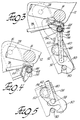
- the rear hooks 50 are normally biased by the torsion springs 54 to the latched position shown in Figures 1 and 3. However, when the rear lift handle 56 is lifted, that is, pulled away from the slotted ends of the legs 26, the rear hooks 50 are rotated against the bias of the torsion springs 54 to the unlatched position unblocking the open end of the slots in the rear legs 26 as shown in phantom in Figure 3. This unlatches the rear seat 10 from the rear mounting pins 30.
- the rear hooks 50 are also locked in the latched position so that the rear seat 10 cannot be unlatched from the rear mounting pins 30 unintentionally when it is installed in the vehicle.
- This second lock feature is provided by a cam shaped release lever 64 which is journalled on a top cross rod portion 66 of the rear lift handle 56.
- This release lever 64 is biased in a clockwise direction with respect to the cross rod portion 66 against a stop pin 68 by a torsion spring 70 as shown in Figures 1 and 3.
- This is a locked position where the cam shaped release lever 64 engages the rear cross member 14 so that the rear lift handle 56 cannot be raised to unlatch the rear hooks 50.
- the centre of the cross rod portion 66 is over centre with respect to the plane 69 containing centres of the trunnions 58 and the rear cross member 14. Consequently, lifting the rear lift handle 56 when the release lever 64 is in the locked position just holds the rear hooks 50 in the latched position with greater force.
- the rear latching mechanism is unlocked by rotating the release lever 64 counterclockwise against the bias of torsion spring 70 until it bottoms out on the other end of the stop pin 68 and the release lever 64 is spaced from the rear cross member 14, as shown in Figure 4.
- the rear lift handle 56 is then lifted to rotate the rear hooks 50 to their unlatched position.
- the rear seat 10 is flipped or pivoted up about the front mounting pins 30 to the vertical or stored position shown in phantom in Figure 1 and in Figure 2.
- the second stop that is the release lever 64, prevents unintentional unlatching of the rear hooks 50.
- a lift assist mechanism for assisting the operator in pivoting the rear seat upwardly about the front mounting pins 30 when the rear hooks 50 are unlatched comprises a torsion bar 72 having an anchor 74 at one end which is secured to one side member 12 and a foot 76 at the other end which is inside the other side member 12.
- the foot 76 engages the vehicle floor 34 so that the torsion bar 72 applies a counterclockwise torque to the seat frame 11.
- the torsion bar 72 is wound up when the rear seat 10 is installed. Consequently, the torsion bar 72 assists in flipping or raising up the rear seat from the installed position shown in Figures 1 and 3 to the stored position shown in Figure 2 when the rear hooks 50 are unlatched.
- the foot 76 is also attached to one of the rear forks or legs 26 by a tie bar 78 so that the rear legs 26 are folded down as the rear seat 10 is raised up to the stored position.
Landscapes
- Engineering & Computer Science (AREA)
- Aviation & Aerospace Engineering (AREA)
- Transportation (AREA)
- Mechanical Engineering (AREA)
- Seats For Vehicles (AREA)
Claims (10)
- Véhicule comportant un siège de véhicule (10) qui comprend un châssis (11) comportant une première et une seconde paires de jambes (24, 26), servant à faire reposer le siège sur des axes de montage (30) disposés dans une première et une seconde paires respectives de cuvettes (32) ménagées dans le plancher du véhicule, des moyens de verrouillage (36), qui servent à verrouiller la première paire de jambes (24) sur deux axes de montage (30) situés dans la première paire de cuvettes (32) et qui comprennent un ou plusieurs premiers crochets (36) agencés de façon à pouvoir être déplacés en rotation entre une position verrouillée et une position déverrouillée, une première poignée (42), permettant de faire tourner le premier crochet ou chaque premier crochet entre les positions verrouillée et déverrouillée, et des moyens de blocage (48) permettant de bloquer le premier crochet ou chaque premier crochet dans la position verrouillée, caractérisé en ce que les moyens de blocage comprennent une butée (48) située dans une cuvette ou dans chaque cuvette (32) de la première paire de cuvettes et servant à empêcher une rotation du premier crochet ou d'un premier crochet associé (36) lorsqu'il est dans une position verrouillée et lorsque le siège est dans un état installé.
- Véhicule selon la revendication 1, dans lequel le premier crochet ou chaque premier crochet (36) est agencé de façon à pouvoir être déplacé en rotation à la position verrouillée lorsque la première paire de jambes (24) est déplacée en rotation vis-à-vis des axes de montage (30) situés dans la première paire de cuvettes (32), de façon à placer le siège dans une position rangée.
- Véhicule selon la revendication 1 ou la revendication 2, comprenant en outre des moyens de verrouillage (50), qui permettent de verrouiller la seconde paire de jambes (26) sur deux axes de montage (30) situés dans la seconde paires de cuvettes (32) et qui comprennent un ou plusieurs seconds crochets (50) agencés de façon à pouvoir être déplacés en rotation entre une position verrouillée et une position déverrouillée, une seconde poignée (56), reliée au second crochet ou à chaque second crochet (50) et permettant de faire tourner le second crochet ou chaque second projet (50) entre les positions verrouillée et déverrouillée, et des moyens de blocage (64) permettant de bloquer le second crochet ou chaque second crochet (50) dans la position verrouillée et comprenant un levier de libération (64) qui est monté d'une manière rotative sur la seconde poignée (56) et est agencé de façon à pouvoir être placé au contact du châssis (11) de façon à maintenir la seconde poignée (56) dans une position inactive, de manière à maintenir le second crochet ou chaque second crochet (50) dans la position verrouillée.
- Véhicule selon la revendication 3 , dans lequel le levier de libération (64) comprend une surface de came, le siège comprenant un ressort (70) servant à repousser élastiquement la surface de came en contact avec un élément transversal (14) du châssis (11) de façon à maintenir la seconde poignée (56) dans la position inactive.
- Véhicule selon la revendication 4, dans lequel le levier de libération (64) est agencé de façon à pouvoir être déplacé en rotation à une position dans laquelle la surface de came est espacée de l'élément transversal (14) de façon à auto-riser une manoeuvre de la seconde poignée (56).
- Véhicule selon la revendication 4 ou 5, dans laquelle la seconde poignée (56) comprend des tourillons (58), qui sont disposés à chacune de ses extrémités et qui sont reliés d'une manière pivotante aux seconds crochets (50), et une partie transversale (66) en forme de tige présentant une ligne centrale qui est située au-delà de la position de point mort vis-à-vis d'un plan contenant les lignes centrales des tourillons et de l'élément transversal (14) du châssis (11).
- Véhicule selon l'une quelconque des revendications 1 à 6, comprenant en outre un mécanisme d'assistance au soulèvement (72-78) destiné à déplacer le châssis de siège (11) à une position rangée dans laquelle le ou les seconds crochets (50) sont déverrouillés, le ou les premiers crochets (36) sont verrouillés et le châssis de siège est déplacé d'une manière pivotante sur les deux axes de montage (30) situés dans la première paire de cuvettes (32), le mécanisme d'assistance au soulèvement comprenant une tige de barre de torsion (78) comportant une première extrémité reliée au châssis et un talon (76) adjacent à une seconde extrémité de ce châssis et destiné à être au contact du plancher du véhicule.
- Véhicule selon la revendication 7, dans lequel la barre de torsion (78) est reliée à un élément latéral (12) du châssis (11) à la première extrémité de la barre de torsion et le talon (76) situé à la seconde extrémité de la barre de torsion est disposé à l'intérieur d'un élément latéral (12) opposé du châssis.
- Véhicule selon la revendication 7 ou 8, dans lequel les jambes (26) de la seconde paire sont montées d'une manière pivotante sur le châssis (11) et le talon (76) du mécanisme de soulèvement (72-78) est relié à l'une des jambes (26) de la seconde paire de façon à faire se plier la seconde paire de jambes vers le châssis de siège lorsqu'on déplace le siège à la position rangée.
- Véhicule selon l'une quelconque des revendications précédentes, dans lequel la première paire de jambes (24) est plus éloignée d'un dossier de siège que la seconde paire de jambes (26).
Applications Claiming Priority (2)
| Application Number | Priority Date | Filing Date | Title |
|---|---|---|---|
| US07/990,206 US5282662A (en) | 1992-12-14 | 1992-12-14 | Rear seat for all purpose vehicle |
| US990206 | 1992-12-14 |
Publications (2)
| Publication Number | Publication Date |
|---|---|
| EP0602696A1 EP0602696A1 (fr) | 1994-06-22 |
| EP0602696B1 true EP0602696B1 (fr) | 1996-09-18 |
Family
ID=25535896
Family Applications (1)
| Application Number | Title | Priority Date | Filing Date |
|---|---|---|---|
| EP93203236A Expired - Lifetime EP0602696B1 (fr) | 1992-12-14 | 1993-11-18 | Siège de véhicule |
Country Status (4)
| Country | Link |
|---|---|
| US (1) | US5282662A (fr) |
| EP (1) | EP0602696B1 (fr) |
| CA (1) | CA2103202C (fr) |
| DE (1) | DE69304874T2 (fr) |
Families Citing this family (41)
| Publication number | Priority date | Publication date | Assignee | Title |
|---|---|---|---|---|
| FR2699973B1 (fr) * | 1992-12-29 | 1995-03-17 | Europ Sieges Automobiles | Verrou à enclenchement de préférence automatique et son application notamment à un siège amovible de véhicule. |
| US5498051A (en) * | 1994-03-07 | 1996-03-12 | Hoover Universal, Inc. | Tumble forward seat |
| US5482345A (en) * | 1994-04-22 | 1996-01-09 | General Motors Corporation | Van-type vehicle seat front riser latch system |
| JP3500717B2 (ja) * | 1994-08-31 | 2004-02-23 | アイシン精機株式会社 | 車両用シート装置 |
| DE19501743A1 (de) * | 1995-01-23 | 1996-07-25 | Daimler Benz Ag | Sitzbank für Kraftfahrzeuge, insbesondere für Kleintransporter |
| FR2735729B1 (fr) * | 1995-06-22 | 1997-08-29 | Irausa Ingeniera | Fixation de securite pour siege amovible de vehicule |
| DE19544833C2 (de) * | 1995-12-01 | 2001-06-21 | Brose Fahrzeugteile | Vorrichtung zur lösbaren Verbindung eines Fahrzeugsitzes mit dem Fahrzeugboden |
| US5775763A (en) * | 1995-12-27 | 1998-07-07 | General Motors Corporation | Vehicle seat connective arrangement |
| FR2749231B1 (fr) * | 1996-05-31 | 1998-09-11 | Cesa | Siege perfectionne a configuration variable pour vehicule automobile |
| FR2750658B1 (fr) * | 1996-07-03 | 1998-11-06 | Ecia Equip Composants Ind Auto | Siege a configuration variable et a manipulation aisee pour vehicule automobile |
| US6142552A (en) * | 1996-08-15 | 2000-11-07 | Lear Corporation | Third automotive seat assembly for an automotive vehicle |
| JPH10173594A (ja) * | 1996-12-06 | 1998-06-26 | Hitachi Ltd | 符号分割多元接続通信システム及び送信電力制御方法 |
| US5944388A (en) * | 1997-05-29 | 1999-08-31 | Ricon Corporation | Removable vehicle seat |
| US6039401A (en) * | 1997-07-28 | 2000-03-21 | Lear Corporation | Self-latching and self-releasing latch mechanism for removable seat |
| JP3426932B2 (ja) | 1997-10-08 | 2003-07-14 | 株式会社今仙電機製作所 | 脱着機構付き可倒シート構造 |
| DE19846031C2 (de) * | 1997-10-08 | 2002-01-17 | Mitsubishi Motors Corp | Lösbarer Klappsitz |
| US6012755A (en) * | 1997-10-15 | 2000-01-11 | Lear Corporation | Foldable automotive seat |
| DE29804542U1 (de) | 1998-03-13 | 1999-07-15 | Johnson Controls GmbH, 51399 Burscheid | Vorrichtung zur Halterung eines Fahrzeugsitzes |
| US5961183A (en) * | 1998-03-25 | 1999-10-05 | General Motors Corporation | Tumble forward seat with automatic seat adjuster return |
| DE29808871U1 (de) | 1998-05-16 | 1999-09-30 | Johnson Controls GmbH, 51399 Burscheid | Vorrichtung zur Halterung eines Fahrzeugsitzes |
| US6631946B1 (en) * | 1998-05-29 | 2003-10-14 | Magna Interior Systems, Inc. | Stowable automotive seat assembly |
| DE19830422C2 (de) * | 1998-07-08 | 2000-06-08 | Ivm Engineering Ag Rotkreuz | Sitzanordnung für ein Kraftfahrzeug |
| JP4147564B2 (ja) * | 1998-09-21 | 2008-09-10 | アイシン精機株式会社 | 車両用シート支持装置 |
| MXPA01003166A (es) * | 1998-10-09 | 2003-05-15 | Magna Seating Sys Inc | Montaje automatizado de asiento de vehiculo del tipo de doblar y abatir. |
| US6793285B1 (en) * | 2000-03-13 | 2004-09-21 | Magna Seating Systems Inc. | Safety mechanism for a fold and tumble seat assembly |
| FR2811273B1 (fr) * | 2000-07-10 | 2002-11-22 | Faure Bertrand Equipements Sa | Dispositif de liaison d'un siege amovible et a assise basculante avec le plancher d'un vehicule automobile |
| US6375245B1 (en) | 2000-10-09 | 2002-04-23 | Johnson Controls Technology Company | Vehicle seating system having chuck reducing apparatus |
| US6698834B2 (en) * | 2001-11-09 | 2004-03-02 | Multiple Llc | Seat connection mechanism |
| FR2832105B1 (fr) * | 2001-11-09 | 2004-01-30 | Faurecia Sieges Automobile | Siege de vehicule comprenant un dispositif d'assistance et vehicule equipe d'un tel siege |
| DE10334420B4 (de) * | 2002-07-29 | 2005-10-20 | Aisin Seiki | Sitzvorrichtung für ein Fahrzeug |
| KR100461102B1 (ko) * | 2002-08-08 | 2004-12-13 | 현대자동차주식회사 | 차량용 리어시트의 리클라이닝 장치 |
| EP1697161B1 (fr) * | 2003-08-01 | 2009-06-17 | Intier Automotive Inc. | Ensemble siege de vehicule et rail de plancher destine au coulissement lateral du siege |
| US7828380B2 (en) * | 2004-01-13 | 2010-11-09 | Series International, Llc | Pew style seating assembly |
| US7204553B2 (en) * | 2004-01-13 | 2007-04-17 | Multiple Llc | Pew or bench with pivoting seat |
| FR2891210B1 (fr) * | 2005-09-29 | 2007-12-21 | Peugeot Citroen Automobiles Sa | Dispositif d'aide au relevage d'un siege de vehicule automobile a une position en portefeuille. |
| US7914077B2 (en) * | 2009-06-18 | 2011-03-29 | Toyota Motor Engineering & Manufacturing North America, Inc. | Single motion load bearing release handle |
| CN102785599B (zh) * | 2012-08-25 | 2015-11-18 | 浙江俱进汽摩配件有限公司 | 一种汽车后排座椅总成 |
| US9694715B1 (en) * | 2015-12-17 | 2017-07-04 | Fca Us Llc | Removable vehicle seat assembly having angled striker surface |
| US10618430B2 (en) * | 2018-05-09 | 2020-04-14 | Polaris Industries Inc. | Seat latch mechanism |
| US11026515B2 (en) | 2018-11-15 | 2021-06-08 | Series International, Llc | Beam seating system |
| US12408756B1 (en) | 2022-05-27 | 2025-09-09 | Series International, Llc | Stacking chair with removable back |
Family Cites Families (9)
| Publication number | Priority date | Publication date | Assignee | Title |
|---|---|---|---|---|
| US3880464A (en) * | 1973-09-24 | 1975-04-29 | Lear Siegler Inc | Double folding second seat |
| US4372610A (en) * | 1980-09-25 | 1983-02-08 | Fisher Corporation | Silent seat back recliner mechanism |
| JPS589836U (ja) * | 1981-07-15 | 1983-01-22 | アイシン精機株式会社 | 車輌用シ−トの二段折れ機構 |
| FR2556946B1 (fr) * | 1983-10-25 | 1986-12-12 | Sable | Siege mobile, notamment siege amovible pour vehicule |
| JPS63137054A (ja) * | 1986-11-28 | 1988-06-09 | Ikeda Bussan Co Ltd | 車両用シ−ト |
| CA1282681C (fr) * | 1987-03-13 | 1991-04-09 | Gulam Premji | Mecanisme de decrochage d'un siege |
| US4865377A (en) * | 1987-12-31 | 1989-09-12 | Knusaga Corporation | Seat riser |
| JP2770289B2 (ja) * | 1988-07-30 | 1998-06-25 | マツダ株式会社 | 自動車のシート装置 |
| FR2682333B1 (fr) * | 1991-10-10 | 1994-01-07 | Peugeot Automobiles | Dispositif de verrouillage d'un siege sur un plancher, en particulier pour vehicule automobile, et siege equipe de ce dispositif. |
-
1992
- 1992-12-14 US US07/990,206 patent/US5282662A/en not_active Expired - Fee Related
-
1993
- 1993-11-16 CA CA002103202A patent/CA2103202C/fr not_active Expired - Fee Related
- 1993-11-18 EP EP93203236A patent/EP0602696B1/fr not_active Expired - Lifetime
- 1993-11-18 DE DE69304874T patent/DE69304874T2/de not_active Expired - Fee Related
Also Published As
| Publication number | Publication date |
|---|---|
| CA2103202A1 (fr) | 1994-06-15 |
| DE69304874T2 (de) | 1997-02-06 |
| CA2103202C (fr) | 1999-03-16 |
| DE69304874D1 (de) | 1996-10-24 |
| US5282662A (en) | 1994-02-01 |
| EP0602696A1 (fr) | 1994-06-22 |
Similar Documents
| Publication | Publication Date | Title |
|---|---|---|
| EP0602696A1 (fr) | Siège de véhicule | |
| US5466048A (en) | Backrest release mechanism | |
| US4268086A (en) | Seat assembly for an automobile | |
| JP3500717B2 (ja) | 車両用シート装置 | |
| US4721338A (en) | Arresting device for rear seat back | |
| US4836597A (en) | Foldable and detachable seat for motor vehicle | |
| JP2680279B2 (ja) | 車両用座席の長手ビームの結合装置 | |
| US8056959B2 (en) | Selectively removable side fairing for a vehicle | |
| US4978158A (en) | Vehicle seat | |
| US6631879B2 (en) | Seat apparatus vehicle | |
| US7325876B2 (en) | Seat assembly with seat back lockout | |
| JP4134364B2 (ja) | 車両用シート構造 | |
| US6183032B1 (en) | Vehicle seating assembly | |
| EP0889799B1 (fr) | Siège basculant avec libération par poignée latérale deplaçable | |
| JP3956334B2 (ja) | 収納式シート | |
| JPH0880774A (ja) | 自動車用の取外し可能な後部座席 | |
| US6974184B1 (en) | Locking mechanism assembly for a cantilevered stowable seat | |
| JP3272560B2 (ja) | キャブロック装置 | |
| US7270361B2 (en) | Vehicle seat | |
| JPS6058048B2 (ja) | 自動車用シ−ト | |
| WO2007080423A1 (fr) | Montage pour dispositif de support de type siège de sécurité pour enfant | |
| JPH10138808A (ja) | 車両の脱着シート構造 | |
| JPH09249073A (ja) | 車両のラゲージスペース規定構造 | |
| JP3502023B2 (ja) | 車両用シートの回転装置 | |
| JPS607947Y2 (ja) | 車両用折畳シ−トのロツク解除装置 |
Legal Events
| Date | Code | Title | Description |
|---|---|---|---|
| PUAI | Public reference made under article 153(3) epc to a published international application that has entered the european phase |
Free format text: ORIGINAL CODE: 0009012 |
|
| AK | Designated contracting states |
Kind code of ref document: A1 Designated state(s): DE FR GB |
|
| 17P | Request for examination filed |
Effective date: 19941222 |
|
| 17Q | First examination report despatched |
Effective date: 19950901 |
|
| GRAG | Despatch of communication of intention to grant |
Free format text: ORIGINAL CODE: EPIDOS AGRA |
|
| GRAH | Despatch of communication of intention to grant a patent |
Free format text: ORIGINAL CODE: EPIDOS IGRA |
|
| GRAH | Despatch of communication of intention to grant a patent |
Free format text: ORIGINAL CODE: EPIDOS IGRA |
|
| GRAA | (expected) grant |
Free format text: ORIGINAL CODE: 0009210 |
|
| AK | Designated contracting states |
Kind code of ref document: B1 Designated state(s): DE FR GB |
|
| REF | Corresponds to: |
Ref document number: 69304874 Country of ref document: DE Date of ref document: 19961024 |
|
| PGFP | Annual fee paid to national office [announced via postgrant information from national office to epo] |
Ref country code: FR Payment date: 19961129 Year of fee payment: 4 |
|
| ET | Fr: translation filed |
Free format text: CORRECTIONS |
|
| PGFP | Annual fee paid to national office [announced via postgrant information from national office to epo] |
Ref country code: DE Payment date: 19970115 Year of fee payment: 4 |
|
| PLBE | No opposition filed within time limit |
Free format text: ORIGINAL CODE: 0009261 |
|
| 26N | No opposition filed | ||
| PG25 | Lapsed in a contracting state [announced via postgrant information from national office to epo] |
Ref country code: GB Free format text: LAPSE BECAUSE OF NON-PAYMENT OF DUE FEES Effective date: 19971118 |
|
| PG25 | Lapsed in a contracting state [announced via postgrant information from national office to epo] |
Ref country code: FR Free format text: THE PATENT HAS BEEN ANNULLED BY A DECISION OF A NATIONAL AUTHORITY Effective date: 19971130 |
|
| GBPC | Gb: european patent ceased through non-payment of renewal fee |
Effective date: 19971118 |
|
| PG25 | Lapsed in a contracting state [announced via postgrant information from national office to epo] |
Ref country code: DE Free format text: LAPSE BECAUSE OF NON-PAYMENT OF DUE FEES Effective date: 19980801 |
|
| REG | Reference to a national code |
Ref country code: FR Ref legal event code: ST |