EP0603398B1 - Blatt mit sägezähnen aus vulkanisierten fasern, karton an den dieses blatt gebunden ist, sowie verfahren zum verbinden - Google Patents
Blatt mit sägezähnen aus vulkanisierten fasern, karton an den dieses blatt gebunden ist, sowie verfahren zum verbinden Download PDFInfo
- Publication number
- EP0603398B1 EP0603398B1 EP92919556A EP92919556A EP0603398B1 EP 0603398 B1 EP0603398 B1 EP 0603398B1 EP 92919556 A EP92919556 A EP 92919556A EP 92919556 A EP92919556 A EP 92919556A EP 0603398 B1 EP0603398 B1 EP 0603398B1
- Authority
- EP
- European Patent Office
- Prior art keywords
- cutting edge
- sheet
- carton
- vulcanized fibre
- serrated
- Prior art date
- Legal status (The legal status is an assumption and is not a legal conclusion. Google has not performed a legal analysis and makes no representation as to the accuracy of the status listed.)
- Expired - Lifetime
Links
Images






Classifications
-
- B—PERFORMING OPERATIONS; TRANSPORTING
- B26—HAND CUTTING TOOLS; CUTTING; SEVERING
- B26D—CUTTING; DETAILS COMMON TO MACHINES FOR PERFORATING, PUNCHING, CUTTING-OUT, STAMPING-OUT OR SEVERING
- B26D1/00—Cutting through work characterised by the nature or movement of the cutting member or particular materials not otherwise provided for; Apparatus or machines therefor; Cutting members therefor
- B26D1/01—Cutting through work characterised by the nature or movement of the cutting member or particular materials not otherwise provided for; Apparatus or machines therefor; Cutting members therefor involving a cutting member which does not travel with the work
- B26D1/04—Cutting through work characterised by the nature or movement of the cutting member or particular materials not otherwise provided for; Apparatus or machines therefor; Cutting members therefor involving a cutting member which does not travel with the work having a linearly-movable cutting member
- B26D1/06—Cutting through work characterised by the nature or movement of the cutting member or particular materials not otherwise provided for; Apparatus or machines therefor; Cutting members therefor involving a cutting member which does not travel with the work having a linearly-movable cutting member wherein the cutting member reciprocates
- B26D1/08—Cutting through work characterised by the nature or movement of the cutting member or particular materials not otherwise provided for; Apparatus or machines therefor; Cutting members therefor involving a cutting member which does not travel with the work having a linearly-movable cutting member wherein the cutting member reciprocates of the guillotine type
- B26D1/085—Cutting through work characterised by the nature or movement of the cutting member or particular materials not otherwise provided for; Apparatus or machines therefor; Cutting members therefor involving a cutting member which does not travel with the work having a linearly-movable cutting member wherein the cutting member reciprocates of the guillotine type for thin material, e.g. for sheets, strips or the like
-
- B—PERFORMING OPERATIONS; TRANSPORTING
- B26—HAND CUTTING TOOLS; CUTTING; SEVERING
- B26D—CUTTING; DETAILS COMMON TO MACHINES FOR PERFORATING, PUNCHING, CUTTING-OUT, STAMPING-OUT OR SEVERING
- B26D1/00—Cutting through work characterised by the nature or movement of the cutting member or particular materials not otherwise provided for; Apparatus or machines therefor; Cutting members therefor
- B26D1/0006—Cutting members therefor
-
- B—PERFORMING OPERATIONS; TRANSPORTING
- B26—HAND CUTTING TOOLS; CUTTING; SEVERING
- B26D—CUTTING; DETAILS COMMON TO MACHINES FOR PERFORATING, PUNCHING, CUTTING-OUT, STAMPING-OUT OR SEVERING
- B26D3/00—Cutting work characterised by the nature of the cut made; Apparatus therefor
- B26D3/10—Making cuts of other than simple rectilinear form
-
- B—PERFORMING OPERATIONS; TRANSPORTING
- B26—HAND CUTTING TOOLS; CUTTING; SEVERING
- B26D—CUTTING; DETAILS COMMON TO MACHINES FOR PERFORATING, PUNCHING, CUTTING-OUT, STAMPING-OUT OR SEVERING
- B26D7/00—Details of apparatus for cutting, cutting-out, stamping-out, punching, perforating, or severing by means other than cutting
- B26D7/27—Means for performing other operations combined with cutting
-
- B—PERFORMING OPERATIONS; TRANSPORTING
- B26—HAND CUTTING TOOLS; CUTTING; SEVERING
- B26F—PERFORATING; PUNCHING; CUTTING-OUT; STAMPING-OUT; SEVERING BY MEANS OTHER THAN CUTTING
- B26F1/00—Perforating; Punching; Cutting-out; Stamping-out; Apparatus therefor
- B26F1/38—Cutting-out; Stamping-out
- B26F1/40—Cutting-out; Stamping-out using a press, e.g. of the ram type
-
- B—PERFORMING OPERATIONS; TRANSPORTING
- B26—HAND CUTTING TOOLS; CUTTING; SEVERING
- B26F—PERFORATING; PUNCHING; CUTTING-OUT; STAMPING-OUT; SEVERING BY MEANS OTHER THAN CUTTING
- B26F3/00—Severing by means other than cutting; Apparatus therefor
- B26F3/02—Tearing
-
- B—PERFORMING OPERATIONS; TRANSPORTING
- B29—WORKING OF PLASTICS; WORKING OF SUBSTANCES IN A PLASTIC STATE IN GENERAL
- B29C—SHAPING OR JOINING OF PLASTICS; SHAPING OF MATERIAL IN A PLASTIC STATE, NOT OTHERWISE PROVIDED FOR; AFTER-TREATMENT OF THE SHAPED PRODUCTS, e.g. REPAIRING
- B29C66/00—General aspects of processes or apparatus for joining preformed parts
- B29C66/40—General aspects of joining substantially flat articles, e.g. plates, sheets or web-like materials; Making flat seams in tubular or hollow articles; Joining single elements to substantially flat surfaces
- B29C66/41—Joining substantially flat articles ; Making flat seams in tubular or hollow articles
- B29C66/43—Joining a relatively small portion of the surface of said articles
-
- B—PERFORMING OPERATIONS; TRANSPORTING
- B29—WORKING OF PLASTICS; WORKING OF SUBSTANCES IN A PLASTIC STATE IN GENERAL
- B29C—SHAPING OR JOINING OF PLASTICS; SHAPING OF MATERIAL IN A PLASTIC STATE, NOT OTHERWISE PROVIDED FOR; AFTER-TREATMENT OF THE SHAPED PRODUCTS, e.g. REPAIRING
- B29C66/00—General aspects of processes or apparatus for joining preformed parts
- B29C66/40—General aspects of joining substantially flat articles, e.g. plates, sheets or web-like materials; Making flat seams in tubular or hollow articles; Joining single elements to substantially flat surfaces
- B29C66/41—Joining substantially flat articles ; Making flat seams in tubular or hollow articles
- B29C66/43—Joining a relatively small portion of the surface of said articles
- B29C66/432—Joining a relatively small portion of the surface of said articles for making tubular articles or closed loops, e.g. by joining several sheets ; for making hollow articles or hollow preforms
- B29C66/4322—Joining a relatively small portion of the surface of said articles for making tubular articles or closed loops, e.g. by joining several sheets ; for making hollow articles or hollow preforms by joining a single sheet to itself
-
- B—PERFORMING OPERATIONS; TRANSPORTING
- B29—WORKING OF PLASTICS; WORKING OF SUBSTANCES IN A PLASTIC STATE IN GENERAL
- B29C—SHAPING OR JOINING OF PLASTICS; SHAPING OF MATERIAL IN A PLASTIC STATE, NOT OTHERWISE PROVIDED FOR; AFTER-TREATMENT OF THE SHAPED PRODUCTS, e.g. REPAIRING
- B29C66/00—General aspects of processes or apparatus for joining preformed parts
- B29C66/40—General aspects of joining substantially flat articles, e.g. plates, sheets or web-like materials; Making flat seams in tubular or hollow articles; Joining single elements to substantially flat surfaces
- B29C66/41—Joining substantially flat articles ; Making flat seams in tubular or hollow articles
- B29C66/43—Joining a relatively small portion of the surface of said articles
- B29C66/432—Joining a relatively small portion of the surface of said articles for making tubular articles or closed loops, e.g. by joining several sheets ; for making hollow articles or hollow preforms
- B29C66/4326—Joining a relatively small portion of the surface of said articles for making tubular articles or closed loops, e.g. by joining several sheets ; for making hollow articles or hollow preforms for making hollow articles or hollow-preforms, e.g. half-shells
-
- B—PERFORMING OPERATIONS; TRANSPORTING
- B29—WORKING OF PLASTICS; WORKING OF SUBSTANCES IN A PLASTIC STATE IN GENERAL
- B29C—SHAPING OR JOINING OF PLASTICS; SHAPING OF MATERIAL IN A PLASTIC STATE, NOT OTHERWISE PROVIDED FOR; AFTER-TREATMENT OF THE SHAPED PRODUCTS, e.g. REPAIRING
- B29C66/00—General aspects of processes or apparatus for joining preformed parts
- B29C66/40—General aspects of joining substantially flat articles, e.g. plates, sheets or web-like materials; Making flat seams in tubular or hollow articles; Joining single elements to substantially flat surfaces
- B29C66/49—Internally supporting the, e.g. tubular, article during joining
-
- B—PERFORMING OPERATIONS; TRANSPORTING
- B29—WORKING OF PLASTICS; WORKING OF SUBSTANCES IN A PLASTIC STATE IN GENERAL
- B29C—SHAPING OR JOINING OF PLASTICS; SHAPING OF MATERIAL IN A PLASTIC STATE, NOT OTHERWISE PROVIDED FOR; AFTER-TREATMENT OF THE SHAPED PRODUCTS, e.g. REPAIRING
- B29C66/00—General aspects of processes or apparatus for joining preformed parts
- B29C66/70—General aspects of processes or apparatus for joining preformed parts characterised by the composition, physical properties or the structure of the material of the parts to be joined; Joining with non-plastics material
- B29C66/71—General aspects of processes or apparatus for joining preformed parts characterised by the composition, physical properties or the structure of the material of the parts to be joined; Joining with non-plastics material characterised by the composition of the plastics material of the parts to be joined
-
- B—PERFORMING OPERATIONS; TRANSPORTING
- B29—WORKING OF PLASTICS; WORKING OF SUBSTANCES IN A PLASTIC STATE IN GENERAL
- B29C—SHAPING OR JOINING OF PLASTICS; SHAPING OF MATERIAL IN A PLASTIC STATE, NOT OTHERWISE PROVIDED FOR; AFTER-TREATMENT OF THE SHAPED PRODUCTS, e.g. REPAIRING
- B29C69/00—Combinations of shaping techniques not provided for in a single one of main groups B29C39/00 - B29C67/00, e.g. associations of moulding and joining techniques; Apparatus therefore
- B29C69/005—Combinations of shaping techniques not provided for in a single one of main groups B29C39/00 - B29C67/00, e.g. associations of moulding and joining techniques; Apparatus therefore cutting-off or cutting-out a part of a strip-like or sheet-like material, transferring that part and fixing it to an article
-
- B—PERFORMING OPERATIONS; TRANSPORTING
- B65—CONVEYING; PACKING; STORING; HANDLING THIN OR FILAMENTARY MATERIAL
- B65D—CONTAINERS FOR STORAGE OR TRANSPORT OF ARTICLES OR MATERIALS, e.g. BAGS, BARRELS, BOTTLES, BOXES, CANS, CARTONS, CRATES, DRUMS, JARS, TANKS, HOPPERS, FORWARDING CONTAINERS; ACCESSORIES, CLOSURES, OR FITTINGS THEREFOR; PACKAGING ELEMENTS; PACKAGES
- B65D83/00—Containers or packages with special means for dispensing contents
- B65D83/08—Containers or packages with special means for dispensing contents for dispensing thin flat articles in succession
- B65D83/0847—Containers or packages with special means for dispensing contents for dispensing thin flat articles in succession through an aperture at the junction of two walls
- B65D83/0852—Containers or packages with special means for dispensing contents for dispensing thin flat articles in succession through an aperture at the junction of two walls with means for assisting dispensing
- B65D83/0882—Containers or packages with special means for dispensing contents for dispensing thin flat articles in succession through an aperture at the junction of two walls with means for assisting dispensing and for cutting interconnected articles
-
- B—PERFORMING OPERATIONS; TRANSPORTING
- B65—CONVEYING; PACKING; STORING; HANDLING THIN OR FILAMENTARY MATERIAL
- B65H—HANDLING THIN OR FILAMENTARY MATERIAL, e.g. SHEETS, WEBS, CABLES
- B65H35/00—Delivering articles from cutting or line-perforating machines; Article or web delivery apparatus incorporating cutting or line-perforating devices, e.g. adhesive tape dispensers
- B65H35/0006—Article or web delivery apparatus incorporating cutting or line-perforating devices
- B65H35/0073—Details
- B65H35/008—Arrangements or adaptations of cutting devices
-
- B—PERFORMING OPERATIONS; TRANSPORTING
- B26—HAND CUTTING TOOLS; CUTTING; SEVERING
- B26D—CUTTING; DETAILS COMMON TO MACHINES FOR PERFORATING, PUNCHING, CUTTING-OUT, STAMPING-OUT OR SEVERING
- B26D1/00—Cutting through work characterised by the nature or movement of the cutting member or particular materials not otherwise provided for; Apparatus or machines therefor; Cutting members therefor
- B26D1/0006—Cutting members therefor
- B26D2001/002—Materials or surface treatments therefor, e.g. composite materials
-
- B—PERFORMING OPERATIONS; TRANSPORTING
- B29—WORKING OF PLASTICS; WORKING OF SUBSTANCES IN A PLASTIC STATE IN GENERAL
- B29C—SHAPING OR JOINING OF PLASTICS; SHAPING OF MATERIAL IN A PLASTIC STATE, NOT OTHERWISE PROVIDED FOR; AFTER-TREATMENT OF THE SHAPED PRODUCTS, e.g. REPAIRING
- B29C65/00—Joining or sealing of preformed parts, e.g. welding of plastics materials; Apparatus therefor
- B29C65/02—Joining or sealing of preformed parts, e.g. welding of plastics materials; Apparatus therefor by heating, with or without pressure
- B29C65/08—Joining or sealing of preformed parts, e.g. welding of plastics materials; Apparatus therefor by heating, with or without pressure using ultrasonic vibrations
-
- B—PERFORMING OPERATIONS; TRANSPORTING
- B29—WORKING OF PLASTICS; WORKING OF SUBSTANCES IN A PLASTIC STATE IN GENERAL
- B29C—SHAPING OR JOINING OF PLASTICS; SHAPING OF MATERIAL IN A PLASTIC STATE, NOT OTHERWISE PROVIDED FOR; AFTER-TREATMENT OF THE SHAPED PRODUCTS, e.g. REPAIRING
- B29C66/00—General aspects of processes or apparatus for joining preformed parts
- B29C66/01—General aspects dealing with the joint area or with the area to be joined
- B29C66/05—Particular design of joint configurations
- B29C66/10—Particular design of joint configurations particular design of the joint cross-sections
- B29C66/11—Joint cross-sections comprising a single joint-segment, i.e. one of the parts to be joined comprising a single joint-segment in the joint cross-section
- B29C66/112—Single lapped joints
- B29C66/1122—Single lap to lap joints, i.e. overlap joints
-
- B—PERFORMING OPERATIONS; TRANSPORTING
- B29—WORKING OF PLASTICS; WORKING OF SUBSTANCES IN A PLASTIC STATE IN GENERAL
- B29C—SHAPING OR JOINING OF PLASTICS; SHAPING OF MATERIAL IN A PLASTIC STATE, NOT OTHERWISE PROVIDED FOR; AFTER-TREATMENT OF THE SHAPED PRODUCTS, e.g. REPAIRING
- B29C66/00—General aspects of processes or apparatus for joining preformed parts
- B29C66/70—General aspects of processes or apparatus for joining preformed parts characterised by the composition, physical properties or the structure of the material of the parts to be joined; Joining with non-plastics material
- B29C66/72—General aspects of processes or apparatus for joining preformed parts characterised by the composition, physical properties or the structure of the material of the parts to be joined; Joining with non-plastics material characterised by the structure of the material of the parts to be joined
- B29C66/723—General aspects of processes or apparatus for joining preformed parts characterised by the composition, physical properties or the structure of the material of the parts to be joined; Joining with non-plastics material characterised by the structure of the material of the parts to be joined being multi-layered
- B29C66/7232—General aspects of processes or apparatus for joining preformed parts characterised by the composition, physical properties or the structure of the material of the parts to be joined; Joining with non-plastics material characterised by the structure of the material of the parts to be joined being multi-layered comprising a non-plastics layer
- B29C66/72327—General aspects of processes or apparatus for joining preformed parts characterised by the composition, physical properties or the structure of the material of the parts to be joined; Joining with non-plastics material characterised by the structure of the material of the parts to be joined being multi-layered comprising a non-plastics layer consisting of natural products or their composites, not provided for in B29C66/72321 - B29C66/72324
- B29C66/72328—Paper
-
- B—PERFORMING OPERATIONS; TRANSPORTING
- B29—WORKING OF PLASTICS; WORKING OF SUBSTANCES IN A PLASTIC STATE IN GENERAL
- B29C—SHAPING OR JOINING OF PLASTICS; SHAPING OF MATERIAL IN A PLASTIC STATE, NOT OTHERWISE PROVIDED FOR; AFTER-TREATMENT OF THE SHAPED PRODUCTS, e.g. REPAIRING
- B29C66/00—General aspects of processes or apparatus for joining preformed parts
- B29C66/70—General aspects of processes or apparatus for joining preformed parts characterised by the composition, physical properties or the structure of the material of the parts to be joined; Joining with non-plastics material
- B29C66/72—General aspects of processes or apparatus for joining preformed parts characterised by the composition, physical properties or the structure of the material of the parts to be joined; Joining with non-plastics material characterised by the structure of the material of the parts to be joined
- B29C66/723—General aspects of processes or apparatus for joining preformed parts characterised by the composition, physical properties or the structure of the material of the parts to be joined; Joining with non-plastics material characterised by the structure of the material of the parts to be joined being multi-layered
- B29C66/7234—General aspects of processes or apparatus for joining preformed parts characterised by the composition, physical properties or the structure of the material of the parts to be joined; Joining with non-plastics material characterised by the structure of the material of the parts to be joined being multi-layered comprising a barrier layer
- B29C66/72343—General aspects of processes or apparatus for joining preformed parts characterised by the composition, physical properties or the structure of the material of the parts to be joined; Joining with non-plastics material characterised by the structure of the material of the parts to be joined being multi-layered comprising a barrier layer for liquids
-
- B—PERFORMING OPERATIONS; TRANSPORTING
- B29—WORKING OF PLASTICS; WORKING OF SUBSTANCES IN A PLASTIC STATE IN GENERAL
- B29K—INDEXING SCHEME ASSOCIATED WITH SUBCLASSES B29B, B29C OR B29D, RELATING TO MOULDING MATERIALS OR TO MATERIALS FOR MOULDS, REINFORCEMENTS, FILLERS OR PREFORMED PARTS, e.g. INSERTS
- B29K2711/00—Use of natural products or their composites, not provided for in groups B29K2601/00 - B29K2709/00, for preformed parts, e.g. for inserts
- B29K2711/12—Paper, e.g. cardboard
- B29K2711/126—Impregnated
-
- B—PERFORMING OPERATIONS; TRANSPORTING
- B31—MAKING ARTICLES OF PAPER, CARDBOARD OR MATERIAL WORKED IN A MANNER ANALOGOUS TO PAPER; WORKING PAPER, CARDBOARD OR MATERIAL WORKED IN A MANNER ANALOGOUS TO PAPER
- B31B—MAKING CONTAINERS OF PAPER, CARDBOARD OR MATERIAL WORKED IN A MANNER ANALOGOUS TO PAPER
- B31B50/00—Making rigid or semi-rigid containers, e.g. boxes or cartons
- B31B50/74—Auxiliary operations
- B31B50/81—Forming or attaching accessories, e.g. opening devices, closures or tear strings
- B31B50/811—Applying strips, strings, laces or ornamental edgings to formed boxes
-
- B—PERFORMING OPERATIONS; TRANSPORTING
- B65—CONVEYING; PACKING; STORING; HANDLING THIN OR FILAMENTARY MATERIAL
- B65D—CONTAINERS FOR STORAGE OR TRANSPORT OF ARTICLES OR MATERIALS, e.g. BAGS, BARRELS, BOTTLES, BOXES, CANS, CARTONS, CRATES, DRUMS, JARS, TANKS, HOPPERS, FORWARDING CONTAINERS; ACCESSORIES, CLOSURES, OR FITTINGS THEREFOR; PACKAGING ELEMENTS; PACKAGES
- B65D2583/00—Containers or packages with special means for dispensing contents
- B65D2583/08—Containers or packages with special means for dispensing contents for dispensing thin flat articles in succession
- B65D2583/082—Details relating to containers for dispensing thin flat articles in succession
- B65D2583/085—Details relating to the cutting means
- B65D2583/087—Details relating to the cutting means with cutting edges being impregnated or coated
-
- B—PERFORMING OPERATIONS; TRANSPORTING
- B65—CONVEYING; PACKING; STORING; HANDLING THIN OR FILAMENTARY MATERIAL
- B65H—HANDLING THIN OR FILAMENTARY MATERIAL, e.g. SHEETS, WEBS, CABLES
- B65H2401/00—Materials used for the handling apparatus or parts thereof; Properties thereof
- B65H2401/10—Materials
-
- Y—GENERAL TAGGING OF NEW TECHNOLOGICAL DEVELOPMENTS; GENERAL TAGGING OF CROSS-SECTIONAL TECHNOLOGIES SPANNING OVER SEVERAL SECTIONS OF THE IPC; TECHNICAL SUBJECTS COVERED BY FORMER USPC CROSS-REFERENCE ART COLLECTIONS [XRACs] AND DIGESTS
- Y10—TECHNICAL SUBJECTS COVERED BY FORMER USPC
- Y10T—TECHNICAL SUBJECTS COVERED BY FORMER US CLASSIFICATION
- Y10T225/00—Severing by tearing or breaking
- Y10T225/20—Severing by manually forcing against fixed edge
- Y10T225/238—With housing for work supply
-
- Y—GENERAL TAGGING OF NEW TECHNOLOGICAL DEVELOPMENTS; GENERAL TAGGING OF CROSS-SECTIONAL TECHNOLOGIES SPANNING OVER SEVERAL SECTIONS OF THE IPC; TECHNICAL SUBJECTS COVERED BY FORMER USPC CROSS-REFERENCE ART COLLECTIONS [XRACs] AND DIGESTS
- Y10—TECHNICAL SUBJECTS COVERED BY FORMER USPC
- Y10T—TECHNICAL SUBJECTS COVERED BY FORMER US CLASSIFICATION
- Y10T225/00—Severing by tearing or breaking
- Y10T225/20—Severing by manually forcing against fixed edge
- Y10T225/238—With housing for work supply
- Y10T225/243—Blade on pivoted closure for housing
-
- Y—GENERAL TAGGING OF NEW TECHNOLOGICAL DEVELOPMENTS; GENERAL TAGGING OF CROSS-SECTIONAL TECHNOLOGIES SPANNING OVER SEVERAL SECTIONS OF THE IPC; TECHNICAL SUBJECTS COVERED BY FORMER USPC CROSS-REFERENCE ART COLLECTIONS [XRACs] AND DIGESTS
- Y10—TECHNICAL SUBJECTS COVERED BY FORMER USPC
- Y10T—TECHNICAL SUBJECTS COVERED BY FORMER US CLASSIFICATION
- Y10T225/00—Severing by tearing or breaking
- Y10T225/20—Severing by manually forcing against fixed edge
- Y10T225/238—With housing for work supply
- Y10T225/248—Single blank container
- Y10T225/249—Blade unitary with container
-
- Y—GENERAL TAGGING OF NEW TECHNOLOGICAL DEVELOPMENTS; GENERAL TAGGING OF CROSS-SECTIONAL TECHNOLOGIES SPANNING OVER SEVERAL SECTIONS OF THE IPC; TECHNICAL SUBJECTS COVERED BY FORMER USPC CROSS-REFERENCE ART COLLECTIONS [XRACs] AND DIGESTS
- Y10—TECHNICAL SUBJECTS COVERED BY FORMER USPC
- Y10T—TECHNICAL SUBJECTS COVERED BY FORMER US CLASSIFICATION
- Y10T225/00—Severing by tearing or breaking
- Y10T225/20—Severing by manually forcing against fixed edge
- Y10T225/257—Blade mounted on hand-held wound package
-
- Y—GENERAL TAGGING OF NEW TECHNOLOGICAL DEVELOPMENTS; GENERAL TAGGING OF CROSS-SECTIONAL TECHNOLOGIES SPANNING OVER SEVERAL SECTIONS OF THE IPC; TECHNICAL SUBJECTS COVERED BY FORMER USPC CROSS-REFERENCE ART COLLECTIONS [XRACs] AND DIGESTS
- Y10—TECHNICAL SUBJECTS COVERED BY FORMER USPC
- Y10T—TECHNICAL SUBJECTS COVERED BY FORMER US CLASSIFICATION
- Y10T225/00—Severing by tearing or breaking
- Y10T225/20—Severing by manually forcing against fixed edge
- Y10T225/282—With fixed blade and support for wound package
-
- Y—GENERAL TAGGING OF NEW TECHNOLOGICAL DEVELOPMENTS; GENERAL TAGGING OF CROSS-SECTIONAL TECHNOLOGIES SPANNING OVER SEVERAL SECTIONS OF THE IPC; TECHNICAL SUBJECTS COVERED BY FORMER USPC CROSS-REFERENCE ART COLLECTIONS [XRACs] AND DIGESTS
- Y10—TECHNICAL SUBJECTS COVERED BY FORMER USPC
- Y10T—TECHNICAL SUBJECTS COVERED BY FORMER US CLASSIFICATION
- Y10T225/00—Severing by tearing or breaking
- Y10T225/20—Severing by manually forcing against fixed edge
- Y10T225/298—Blades or severing devices
Definitions
- the present invention relates to a sheet having a serrated cutting edge for cutting what is called a cooking sheet such as a wrapping film of a synthetic resin, paper sheet and metallic foil, and to a carton case to which the sheet having a serrated cutting edge is adhered.
- the present invention also includes a method of adhering the sheet having a serrated cutting edge to the carton case.
- the sheet being made of a vulcanized fibre having a special composition.
- a material generally called a cooking sheet such as a wrapping film of a synthetic resin and aluminium foil used in the kitchen, etc. for wrapping foods or the like, is usually rolled up and contained in a paperboard carton case (hereinafter referred to as the "carton").
- a cutting member or a serrated cutting edge provided on a front portion or a cover portion of the carton (hereinafter referred to as the "cutting edge” or “serrated cutting edge”).
- each cutting tooth and the distribution of the cutting teeth are of little importance.
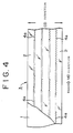
- the cutting edge has a certain length and, the cutting teeth of the cutting edge are distributed straight. It has been found that if each cutting tooth in the central portion of the cutting edge has the shape of an isosceles triangle and each cutting tooth in the remaining end portions of the cutting edge has the shape of a scalene triangle inclined outward, then the cutting edge can even cut well a film having relatively large elongation.
- the serrated cutting edge of the sheet may be either formed straight as mentioned above or bent angularly in the lengthwise direction.
- the vulcanized fibre sheet provided with the serrated cutting edge is attached to a carton as mentioned above.
- the sheet may be attached to the carton by means of a suitable adhesive (including a pressure-sensitive adhesive). If the following method of adhesion is used, various superior effects as mentioned below will be obtained as compared with the case where the adhesive is used.
- the sheet having the serrated cutting edge has an excellent dimensional stability, even though the sheet is made of vulcanized fibre. Consequently, the serrated cutting edge has good cutting ability.
- the adhesion is strong and free from peeling.
- the main material used in the present invention is a vulcanized fibre which, as is generally known, comprises a cotton fibre or chemical pulp made into a base paper without sizing, the base paper being treated with a zinc chloride solution having a certain concentration (Baume degree generally being 65 to 74).
- the vulcanized fibre has properties intermediate to those of wood and metal.
- the vulcanized fibre has high elasticity and rigidity, is much lighter than metal and, has a high resistance to various oils.
- the present invention obtains the above-mentioned sheet having a serrated cutting edge by utilising the properties of the vulcanized fibre and subjecting the vulcanized fibre to special treatment.
- the present invention provides a carton having a useful cutting edge which replaces the conventional metal cutting edge.
- the sheet having a serrated cutting edge has a thickness of 0.2 to 0.5 mm, preferably 0.25 to 0.35 mm. As the thickness decreases, the cutting edge cuts better.
- an emulsion of a polyethylene resin for example may be applied in advance as an adhesion accelerator to the carton blank at a position to which the sheet is to be adhered, a film thus formed in advance increases the adhesion between the sheet and the carton blank.
- a paper stuff comprising 50% of NBKP and 50% of NDSP was made into a base paper having a basic weight of 105 g/m 2 .
- Two pieces of this base paper were immersed in a zinc chloride solution of 69° Be and 40°C, subjected to pressing, adhesion under heat and pressure and air aging, then put into a tank containing a zinc chloride solution of about 30° Be, and aged in a tank containing a zinc chloride solution having a low concentration so that zinc chloride melted away.
- the serrated cutting edges may be formed either in the machine direction or in the cross direction.
- the moisture-proof film 2 is formed on both of the surfaces of the blank 1 with the intention mentioned above and then a long rectangular sheet 4 having a serrated cutting edge as shown in Figure 1 is obtained.
- a flat sheet of 0.8 cm X 30 cm having a thickness of about 0.25 mm was obtained.
- the front wall panel 12, rear wall panel 13 and side panels 19 are vertically erected along fold lines from the bottom wall panel 11, glue flaps 16 and 17 are adhered inside the side plates 19, then a rolled cooking sheet (see reference symbol G in Figure 7) is put into the carton. After that, the opening of the carton is closed by the top wall panel 14 and cover panel 15. Then, the cover plate is fixed to the front wall panel 12 by the spot adhesion H of the temporarily attached pieces 23 thereto.
- the carton is opened by cutting off the temporarily attached pieces 23, which are spot adhered, along the perforated lines, the end of the wrapping film or sheet F of the roll G is held between the fingers, then a desired length thereof is pulled out.
- the film, etc. is pulled down along the front wall panel 12 and cut to the desired length by being pushed against the front wall panel 12, that is, by means of the serrated cutting edge 4a protruding from the lower edge of the front wall panel 12.
- the insertion piece 22 is inserted into the holding slit 24 in the front wall panel 12 to close the carton, thereby preventing dust from entering the carton.
- a cover panel 25 is continuously provided on the upper side of a top wall panel 14.
- the sheet 5 having a serrated cutting edge is adhered to the cover panel.
- a perforated line 26 corresponding to the shape of the sheet 5 is provided on the cover panel.
- a separation piece 27 on the outside of the perforated line 26 is cut off along the perforated line 26 and the carton is opened. After the separation piece 27 is separated from the cover panel 25, the serrated cutting edge 4a of the sheet 5 protrudes from the edge of the cover panel. Therefore, it is possible to cut the film or sheet to a desired length by means of the serrated cutting edge.
- portions or members of the carton blank P' corresponding to those in the above-mentioned example are represented by the same symbols thereas.
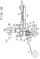
- Reference symbol 30 in Figure 10 represents an ultrasonic adhering device, which is mounted in an upper bolster 31 of a known die set mechanism for example.
- the ultrasonic adhering device comprises an ultrasonic generator 30a, an ultrasonic vibrator 30b and a horn 30c. Electric vibrations generated by the ultrasonic generator 30a are converted into mechanical vibrations by the ultrasonic vibrator 30b. Then, the mechanical vibrations are amplified by the horn 30c. The amplified vibrations are transmitted to the moisture-proof film of the sheet having a serrated cutting edge and melts the film by heating it. Thereby the sheet 3, in which the serrated cutting edge 4a has just been formed, is adhered to the carton blank P or P'.
- the adhesion between the sheet and the carton blank is further increased by coating the adhesion portion of the carton blank in advance with an anchoring agent such as an emulsion of polyethylene imine, polyethylene or polyvinylidene chloride resin, the anchoring agent being dried so as to form a film.
- an anchoring agent such as an emulsion of polyethylene imine, polyethylene or polyvinylidene chloride resin
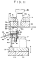
- reference symbol 32 represents an upper plate in the die set mechanism.
- a holder plate 35 by which an upper cutting edge 34 is held, the clearance 33 between the upper plate 32 and the holder plate 35 being very small.
- the upper cutting edge 34 is fixed to the lower surface of the holder plate 35.
- a sheet clamper 36 is disposed under the upper cutting edge 34, there being a certain clearance between the upper cutting edge 34 and the sheet clamper 36.
- a lower cutting edge 37 corresponding to the upper cutting edge 34 is disposed beside and below the sheet clamper 36, the lower cutting edge 37 and the upper cutting edge 34 facing each other.
- Reference symbol 38 represents a mount of the lower cutting edge 37, reference symbol 39 representing a lower plate, reference symbol 40 representing a lower bolster, these being adapted to be integrally moved up and down by a cam mechanism or a cylinder mechanism not shown in the Figures.
- Reference symbol 41 represents a stay bolt embedded in a lower portion of the holder plate 35, the stay bolt 41 passing through the upper cutting edge 34 and the sheet clamper 36.
- a protruding portion of the stay bolt 41 is provided with a spring 42 which has a tendency to push up the lower surface of the sheet clamper 36.
- the lower plate 39 has a recess 41a in which the stay bolt 41 sinks when the lower bolster 40 of the die set mechanism moves up.
- Beside the stay bolt 41 there is a guide rod 43 which gives a small clearance between the sheet clamper 36 and the upper cutting edge 34 by pulling down the sheet clamper 36 within a certain range against the force of the spring 42 when the die set mechanism opens.
- the guide rod 43 is provided at its top with a bolt head 43a which contacts the upper surface of the sheet clamper 36 as shown by dotted lines in Figure 11.
- the bolt head 43a pulls down the sheet clamper 36.
- a blank sheet 3 for forming a serrated cutting edge is sent into the clearance between the sheet clamper 36 and the upper cutting edge 34.
- the guide rod 43 moves up and down when the die set opens and closes. As the guide rod 43 moves up and down, the bolt head 43a moves through a hole 43b bored through all of the upper cutting edge 34, holder plate 35 and upper plate 32.
- a carton blank P is supplied to a position under the upper plate 32 so as to oppose the ultrasonic adhesion horn 30c. Beside the die set mechanism, there is a belt conveyor 44 for feeding the blank and pressing rollers 45 above the belt conveyor 44 as shown in Figure. 10. The sheet 3, not having a serrated cutting edge, is supplied through nip rollers 46 to the die set mechanism. The relationship between the upper cutting edge 34 and the lower cutting edge 37 is shown in Figure 13, each of them having a serrated cutting edge, these cutting edges being engageable with each other.
- the carton blank P is supplied by means of the belt conveyor 44 and the pressing rollers 45 to a position under the upper plate and directly below the adhesion horn 30c as shown by an arrow, the blank sheet 3 for forming a serrated cutting edge being supplied between the upper cutting edge 34 and the sheet clamper 36.
- the bolt head 43a of the guide rod 43 pushes down the sheet clamper 36 as shown in Figure 11. Therefore, a certain clearance is formed between the clamper 36 and the upper cutting edge 34. Through this clearance, the blank sheet 3 is intermittently supplied from the nip rollers 46. After the blank sheet is supplied, the die set mechanism starts closing.
- the sheet 3 for forming a serrated cutting edge is supplied as mentioned above so that a certain length thereof protrudes from the upper cutting edge 34 over the lower cutting edge 37 as shown in the Figure.
- the die set mechanism starts closing as shown in Figure 12.
- the lower cutting edge 37 moves upward and cuts the blank sheet 3 to form a serrated cutting edge.
- the lower cutting edge 37 pushes up the sheet having the serrated cutting edge against a predetermined portion of the carton blank P waiting above the sheet as shown in Figure 12.
- a pressure-sensitive switch (not shown) of the, ultrasonic adhering device 30 is turned on to start the adhering device.
- the adhering device melts the moisture-proof film formed on the surface of the sheet to adhere the sheet 3 to the predetermined portion of the carton blank P.
- the ultrasonic adhering device is not limited to the device described above and may comprise a vibrator 30a and a horn 30c, energy generated by the vibrator 30a being converted into vibrations in the vertical direction by the horn as shown in Figure 15.
- Rectangular sheets having a width of 8 mm and a length of 100 mm were cut out of each of the samples.
- the direction in which the serrated cutting edge was to be formed was the lengthwise direction of each sheet as shown in Figures 3 and 4. Two types of these rectangular sheets were obtained. In one of the two types, the lengthwise direction was parallel to MD (shown as “long.” in Tables 3 and 4 below). In the other of the two types, the lengthwise direction was parallel to CD (shown as "lat.” in Tables 3 and 4 below).
- the samples were tested as to the degrees of the contraction and elongation thereof according to the differences of humidity.
- the vulcanized fibre sheet provided with the moisture-proof film is used as a blank, and a serrated cutting edge is formed on the vulcanized fibre sheet by utilising its very high elasticity and rigidity. Therefore, the serrated cutting edge is free from deformation or damage by an external force and always cuts very well.
- the sheet of the present invention maintains its dimensional stability even when it is kept in a kitchen, for example, having a high humidity. Therefore, the sheet having a serrated cutting edge according to the present invention is suitable for cutting cooking sheets of a resin film, paper, metal foil, treated paper, etc. used for packing foods.
- the sheet having a serrated cutting edge is made of the vulcanized fibre, the sheet does not injure fingers, even when it is attached to a carton. After use, the whole carton having the sheet may be burned as it is, with no residue being left, unlike conventional metal cutting edges.
- a serrated cutting edge in which all the cutting teeth have the shape of a uniform isosceles triangle As compared with a serrated cutting edge in which all the cutting teeth have the shape of a uniform isosceles triangle, a serrated cutting edge in which each cutting tooth in the end portions of the cutting edge has the shape of a scalene triangle inclined outward, cuts surely into a film without slipping and is effective in cutting films having a large elongation such as polyethylene film and polyvinyl chloride film.
Landscapes
- Engineering & Computer Science (AREA)
- Mechanical Engineering (AREA)
- Life Sciences & Earth Sciences (AREA)
- Forests & Forestry (AREA)
- Cartons (AREA)
Claims (15)
- Vulkanfiberblatt (4) mit einer gezahnten Schneidkante (4a), das einen Vulkanfiberzuschnitt (1) aufweist, dadurch gekennzeichnet, daß es zwei Außenflächen hat, die mit einem Feuchtigkeitsschutzfilm (2) versehen sind, der aus einem Film aus Polyethylen niederer Dichte besteht, wobei die gezahnte Schneidkante (4a) an mindestens einer Kante des Blatts (4) geformt ist.
- Vulkanfiberblatt nach Anspruch 1, dadurch gekennzeichnet, daß der Feuchtigkeitsschutzfilm (2) über einem wasserbeständigen Agens gebildet ist, das auf dem Vulkanfiberzuschnitt (1) aufgetragen ist.
- Vulkanfiberblatt nach Anspruch 1 und Anspruch 2, dadurch gekennzeichnet, daß das Blatt (4) die Form eines Rechtecks und eine Vielzahl von Schneidzähnen auf einer Schneidkante des Blatts aufweist, wobei jeder Schneidzahn (4a) in einem mittleren Abschnitt (X) der Schneidkante die Form eines gleichschebkligen Dreiecks hat, jeder Schneidzahn (4b) in den äußeren Endabschnitten (Y) der Schneidkante die Form eines schiefen Dreiecks hat, das weggerichtet von dem mittleren Abschnitt (X) der Schneidkante geneigt ist.
- Vulkanfiberblatt nach Anspruch 2 und einem auf diesen rückbezogenen Anspruch, dadurch gekennzeichnet, daß das wasserbeständige Agens ein Melaminharz oder Glyoxal ist.
- Vulkanfiberblatt nach einem der vorhergehenden Ansprüche, dadurch gekennzeichnet, daß die gezahnte Schneidkante (4a) eine Dicke zwischen 0,2 mm und 0,5 mm hat.
- Vulkanfiberblatt nach einem der vorhergehenden Ansprüche, dadurch gekennzeichnet, daß die gezahnte Schneidkante (4a) eine Dicke zwischen 0,25 mm und 0,35 mm hat.
- Vulkanfiberblatt nach Anspruch 3 und einem auf diesen rückbezogenen Anspruch, dadurch gekennzeichnet, daß das schiefe Dreieck einen Scheitelwirkel von ungefähr 58° hat.
- Vulkanfiberblatt nach Anspruch 3 und einem auf diesen rückbezogenen Anspruch, dadurch gekennzeichnet, daß das schiefe Dreieck einen Scheitelwinkel von ungefähr 49° hat.
- Karton, an den ein eine gezahnte Schneidkante (4a) und zwei Außenflächen aufweisendes Vulkanfiberblatt (4) angeklebt ist, wobei der Karton einen Kartonrumpf und eine Abdeckung aufweist, der Kartonrumpf einen flachen Bodenwandabschnitt (11), einen flachen Vorderwandabschnitt (12), einen flachen Rückwandabschnitt (13) und flache Seitenabschnitte (19) aufweist und die Abdeckung die Öffnung des Kartonrumpfes abdeckt, dadurch gekennzeichnet, daß ein Feuchtigkeitsschutzfilm (2) auf den zwei Außenflächen des Vulkanfiberblatts (4) gebildet ist, wobei der Feuchtigkeitsschutzfilm (2) ein Film aus Polyethylen niederer Dichte ist.
- Karton nach Anspruch 9, dadurch gekennzeichnet, daß das Blatt (4) auf eine getrocknete, auf einen Kartonzuschnitt aufgetragene Polyethylenemulsion geklebt ist.
- Karton nach Anspruch 9 oder Anspruch 10, dadurch gekennzeichnet, daß die gezahnte Schneidkante (4a) eine Dicke zwischen 0,2 mm und 0,5 mm hat.
- Karton nach einem der Ansprüche 9 bis 11, dadurch gekennzeichnet, daß die gezahnte Schneidkante (4a) einen mittleren Abschnitt (X) mit einer Vielzahl von Schneidzähnen (4a) von der Form eines gleichschenkligen Dreiecks und zwei äußere Abschnitte (Y) mit einer Vielzahl von Schneidzähnen (4b) von der Form eines schiefen, von dem mittleren Abschnitt der gezahnten Schneidkante (4a) weggerichteten Dreiecks aufweist.
- Verfahren zum Ankleben eines eine gezahnte Schneidkante (4a) aufweisenden Vulkanfiberblatts (4) an einen Kartonzuschnitt (P), wobei der Kartonzuschnitt (P) einen flachen Bodenwandabschnitt (11), einen flachen Vorderwandabschnitt (12), einen flachen Rückwandabschnitt (13), flache Seitenabschnitte (19) und eine Abdeckung (15) aufweist, dadurch gekennzeichnet, daß das Verfahren die Schritte des Bildens eines aus einem Film aus Polyethylen niederer Dichte bestehenden Feuchtigkeitsschutzfilms (2) auf dem Vulkanfiberblatt (4) und des Anklebens des Vulkanfiberblatts (4) durch den Feuchtigkeitsschutzfilm (2) an einen vorbestimmten Abschnitt des Kartonzuschnitts (P) mittels eines Ultraschallklebeverfahrens aufweist.
- Verfahren nach Anspruch 13, dadurch gekennzeichnet, daß die gezahnte Schneidkante (4a) eine Dicke zwischen 0,2 und 0,5 mm hat.
- Verfahren nach Anspruch 13 oder Anspruch 14, dadurch gekennzeichnet, daß die gezahnte Schneidkante (4a) einen mittleren Schneidabschnitt (X) mit einer Vielzahl von Schneidzähnen (4a) von der Form eines gleichschenkligen Dreiecks und zwei äußere Abschnitte (Y) mit einer Vielzahl von Schneidzähnen (4b) von der Form eines schiefen, von dem mittleren Abschnitt der gezahnten Schneidkante (4a) weggerichteten Dreiecks aufweist.
Applications Claiming Priority (5)
| Application Number | Priority Date | Filing Date | Title |
|---|---|---|---|
| JP8164091U JPH068229U (ja) | 1991-02-18 | 1991-09-12 | バルカナイズドファイバー歯付カートン |
| JP81640/91U | 1991-09-12 | ||
| JP11677392 | 1992-04-10 | ||
| JP116773/92 | 1992-04-10 | ||
| PCT/JP1992/001176 WO1993004935A1 (fr) | 1991-09-12 | 1992-09-14 | Feuille avec partie en dents de scie, fabriquee a partir de fibres vulcanisees, carton auquel est collee cette feuille, et procede de collage |
Publications (3)
| Publication Number | Publication Date |
|---|---|
| EP0603398A1 EP0603398A1 (de) | 1994-06-29 |
| EP0603398A4 EP0603398A4 (de) | 1995-10-04 |
| EP0603398B1 true EP0603398B1 (de) | 1997-06-11 |
Family
ID=26422642
Family Applications (1)
| Application Number | Title | Priority Date | Filing Date |
|---|---|---|---|
| EP92919556A Expired - Lifetime EP0603398B1 (de) | 1991-09-12 | 1992-09-14 | Blatt mit sägezähnen aus vulkanisierten fasern, karton an den dieses blatt gebunden ist, sowie verfahren zum verbinden |
Country Status (4)
| Country | Link |
|---|---|
| US (1) | US6173876B1 (de) |
| EP (1) | EP0603398B1 (de) |
| DE (1) | DE69220373T2 (de) |
| WO (1) | WO1993004935A1 (de) |
Families Citing this family (27)
| Publication number | Priority date | Publication date | Assignee | Title |
|---|---|---|---|---|
| GB2323074B (en) * | 1994-12-20 | 1999-06-30 | Dainippon Printing Co Ltd | Sawtooth cutter |
| JP3894964B2 (ja) * | 1994-12-20 | 2007-03-22 | 大日本印刷株式会社 | 鋸刃カッターの接着方法 |
| GB9620296D0 (en) * | 1996-09-28 | 1996-11-13 | Carton Edge Ltd | Apparatus for mounting a cutting strip |
| US5839634A (en) * | 1997-01-27 | 1998-11-24 | The Procter & Gamble Co. | Blade for severing sheet materials |
| DE69916634T2 (de) * | 1998-09-16 | 2005-03-31 | Adalis Corporation, Vancouver | Klebefilm zur ausbildung einer schneidekante in kartonspendern |
| US6405913B1 (en) * | 1999-12-22 | 2002-06-18 | Green Bay Packaging, Inc. | Paperboard dispenser carton with plastic cutting blade |
| JP4211179B2 (ja) * | 2000-01-31 | 2009-01-21 | セイコーエプソン株式会社 | 印刷装置 |
| AU2000233846A1 (en) * | 2000-02-29 | 2001-09-12 | Carton Edge Limited | Serrated cutting strip |
| US6851592B1 (en) * | 2000-02-29 | 2005-02-08 | Carton Edge Systems Limited | Serrated cutting strip |
| WO2002039219A2 (en) | 2000-11-01 | 2002-05-16 | Linear Products Inc. | Web material advance system for web material applicator |
| US6893528B2 (en) * | 2000-11-01 | 2005-05-17 | Adalis Corporation | Web material advance system for web material applicator |
| US20030091779A1 (en) * | 2001-11-13 | 2003-05-15 | Brewster Frederick H. | Cutting edge for dispenser cartons |
| US20030164392A1 (en) * | 2002-03-01 | 2003-09-04 | Gerulski Kristopher W. | Wrap dispenser with enhanced cutter bar registration |
| US7172666B2 (en) * | 2002-12-17 | 2007-02-06 | Groves Matthew E | Web material application methods and systems |
| EP1619140A1 (de) * | 2004-07-12 | 2006-01-25 | Widee B.V. | Verpackung für eine Folienrolle |
| JP5069075B2 (ja) * | 2007-10-01 | 2012-11-07 | 株式会社クレハ | 包装容器用の切断刃及びそれを有する包装容器 |
| JP5374036B2 (ja) * | 2007-11-29 | 2013-12-25 | 株式会社クレハ | 包装容器用の切断刃及び包装容器 |
| MX2010008652A (es) * | 2008-02-07 | 2010-12-21 | Nestec Sa | Cuchillas y ensambles de corte. |
| JP2011219271A (ja) * | 2010-03-25 | 2011-11-04 | Seiko Epson Corp | 記録装置 |
| JP5867430B2 (ja) * | 2013-03-14 | 2016-02-24 | ソニー株式会社 | 医療用プリンタ |
| USD791205S1 (en) * | 2015-04-06 | 2017-07-04 | Zenith Cutter, Inc. | Serrated male slot knife |
| CN105002781B (zh) * | 2015-05-30 | 2017-07-11 | 玛纳斯源源纸业有限公司 | 一种避免钢纸发白的生产方法 |
| USD791206S1 (en) * | 2015-07-31 | 2017-07-04 | Zenith Cutter, Inc. | Serrated male slot knife |
| CN109573207A (zh) * | 2018-12-29 | 2019-04-05 | 天津兴雅医疗设备科技有限公司 | 一种药品包装设备的扎剪机构刀片 |
| USD895731S1 (en) * | 2019-01-30 | 2020-09-08 | American Greetings Corporation | Label |
| WO2020188899A1 (ja) * | 2019-03-19 | 2020-09-24 | 株式会社クレハ | 切断刃および包装容器 |
| DE102021214074B3 (de) | 2021-12-09 | 2023-04-27 | Philipp Buhlmann | Schneidwerkzeug und Verfahren zur Herstellung eines Schneidwerkzeugs |
Citations (1)
| Publication number | Priority date | Publication date | Assignee | Title |
|---|---|---|---|---|
| US3169685A (en) * | 1962-11-14 | 1965-02-16 | United Shoe Machinery Corp | Serrated tearing edges |
Family Cites Families (15)
| Publication number | Priority date | Publication date | Assignee | Title |
|---|---|---|---|---|
| US3622751A (en) * | 1969-06-12 | 1971-11-23 | Cons Paper Bahamas Ltd | Method and apparatus for electrically perforating sheet or web material |
| US4580709A (en) * | 1981-12-24 | 1986-04-08 | Champion International Corporation | Dispensing carton having material tear strip and blank therefor |
| US4679718A (en) * | 1985-03-25 | 1987-07-14 | Asahi Kasei Kogyo Kabushiki Kaisha | Cutter for dispensing container and dispensing container provided with said cutter |
| JP2563113B2 (ja) | 1987-10-29 | 1996-12-11 | マツダ株式会社 | 4輪駆動車の駆動モード切換制御装置 |
| US4822440A (en) * | 1987-11-04 | 1989-04-18 | Nvf Company | Crossband and crossbanding |
| JPH0427777Y2 (de) * | 1988-01-28 | 1992-07-03 | ||
| JPH01294429A (ja) | 1988-05-09 | 1989-11-28 | Isao Nakamura | 鋸歯状縁を有する繊維性シートおよびこれからなる箱並びにこれを生産する刃物 |
| US5103598A (en) * | 1989-04-28 | 1992-04-14 | Norton Company | Coated abrasive material containing abrasive filaments |
| JPH0326719A (ja) | 1989-06-26 | 1991-02-05 | Toray Ind Inc | ナフト[2,3―c]チオフェン構造を有する重合体の製造方法 |
| JPH0326719U (de) * | 1989-07-21 | 1991-03-19 | ||
| DE4101762C2 (de) * | 1990-01-22 | 2002-06-27 | Okumura Ayako | Verfahren und Vorrichtung zum Ausbilden einer Schneideinrichtung an einem Karton |
| US5135784A (en) * | 1990-07-31 | 1992-08-04 | Ayako Okumura | Wrapping web container and cutter for cutting wrapping web |
| US5314513A (en) * | 1992-03-03 | 1994-05-24 | Minnesota Mining And Manufacturing Company | Abrasive product having a binder comprising a maleimide binder |
| US5226571A (en) * | 1992-05-01 | 1993-07-13 | Central Box And Container Limited | Box dispenser made from corrugated board |
| US5732868A (en) * | 1994-04-20 | 1998-03-31 | Reynolds Metals Company | System for safely storing and dispensing a thin sheet-like material |
-
1992
- 1992-09-14 EP EP92919556A patent/EP0603398B1/de not_active Expired - Lifetime
- 1992-09-14 US US08/758,979 patent/US6173876B1/en not_active Expired - Fee Related
- 1992-09-14 DE DE69220373T patent/DE69220373T2/de not_active Expired - Fee Related
- 1992-09-14 WO PCT/JP1992/001176 patent/WO1993004935A1/ja not_active Ceased
Patent Citations (1)
| Publication number | Priority date | Publication date | Assignee | Title |
|---|---|---|---|---|
| US3169685A (en) * | 1962-11-14 | 1965-02-16 | United Shoe Machinery Corp | Serrated tearing edges |
Also Published As
| Publication number | Publication date |
|---|---|
| EP0603398A4 (de) | 1995-10-04 |
| US6173876B1 (en) | 2001-01-16 |
| WO1993004935A1 (fr) | 1993-03-18 |
| EP0603398A1 (de) | 1994-06-29 |
| DE69220373D1 (de) | 1997-07-17 |
| DE69220373T2 (de) | 1997-11-20 |
Similar Documents
| Publication | Publication Date | Title |
|---|---|---|
| EP0603398B1 (de) | Blatt mit sägezähnen aus vulkanisierten fasern, karton an den dieses blatt gebunden ist, sowie verfahren zum verbinden | |
| US7090740B2 (en) | Techniques for labeling of plastic, glass or metal containers or surfaces with polymeric labels | |
| CA2120111A1 (en) | Method of applying adhesive to porous materials | |
| US4216046A (en) | Manufacture of articles of polyvinyl chloride foil with sealed-in reinforcement material | |
| US7204910B2 (en) | Film tape for forming a cutting edge on dispenser cartons | |
| EP2340161B1 (de) | Herstellungsverfahren | |
| US5064579A (en) | Process of producing an oriented silicone resin coated polymeric film | |
| EP2616240B1 (de) | Polymermaterial für etiketten | |
| JP2606776B2 (ja) | バルカナイズドファイバー製の鋸歯刃つきシートをカートンケースに接着させる方法 | |
| RU98108762A (ru) | Ламинированный упаковочный материал, способ его изготовления и упаковочный контейнер, изготовленный из этого материала и обладающий высокой непроницаемостью для газообразного кислорода | |
| JP2571121Y2 (ja) | バルカナイズドファイバー製の鋸歯刃つきシートならびに該シートを接着させたカートン | |
| JP2824901B2 (ja) | 鋸歯刃つきシートをカートンケースに接着させる方法ならびに装置 | |
| JPH037789A (ja) | 発泡接着剤付き留め具バンドおよび作成方法 | |
| JPH06182906A (ja) | バルカナイズドファイバー製鋸歯刃の高速接着方法 | |
| JP2593400B2 (ja) | バルカナイズドファイバー製の鋸歯刃つきシート及び該シートを接着させたカートンならびにその接着法 | |
| US3380583A (en) | Package | |
| DE2432895A1 (de) | Verfahren und vorrichtung zur stoss-anstoss-verbindung von materialzuschnitten und bahnen aus papier, pappe, kunststoff, holz o. ae. sowie verklebestreifen zur durchfuehrung des verfahrens | |
| DE60225615T2 (de) | Thermogeformte Platte mit Schall und thermischen Isolationseigenschaften | |
| JP3952320B2 (ja) | 粘着テープ巻回積層体の側面処理方法 | |
| JPH08174720A (ja) | 鋸刃カッターの接着方法及び紙鋸刃カッター | |
| JPH04125104A (ja) | 化粧板の製造方法 | |
| WO2003061969A1 (en) | Laminate material for paper containers and paper containers for liquids | |
| EP0385794A1 (de) | Verfahren zum Härten der Kanten einer Vielzahl von Kartonzuschnitten | |
| JPS623213Y2 (de) | ||
| JP2000178514A (ja) | 粘着シート |
Legal Events
| Date | Code | Title | Description |
|---|---|---|---|
| PUAI | Public reference made under article 153(3) epc to a published international application that has entered the european phase |
Free format text: ORIGINAL CODE: 0009012 |
|
| 17P | Request for examination filed |
Effective date: 19940324 |
|
| AK | Designated contracting states |
Kind code of ref document: A1 Designated state(s): DE FR GB IT |
|
| A4 | Supplementary search report drawn up and despatched | ||
| AK | Designated contracting states |
Kind code of ref document: A4 Designated state(s): DE FR GB IT |
|
| 17Q | First examination report despatched |
Effective date: 19960126 |
|
| GRAG | Despatch of communication of intention to grant |
Free format text: ORIGINAL CODE: EPIDOS AGRA |
|
| GRAH | Despatch of communication of intention to grant a patent |
Free format text: ORIGINAL CODE: EPIDOS IGRA |
|
| ITF | It: translation for a ep patent filed | ||
| GRAH | Despatch of communication of intention to grant a patent |
Free format text: ORIGINAL CODE: EPIDOS IGRA |
|
| GRAH | Despatch of communication of intention to grant a patent |
Free format text: ORIGINAL CODE: EPIDOS IGRA |
|
| GRAA | (expected) grant |
Free format text: ORIGINAL CODE: 0009210 |
|
| RAP1 | Party data changed (applicant data changed or rights of an application transferred) |
Owner name: TOYO FIBRE CO., LTD. Owner name: OJI PAPER CO., LTD. |
|
| AK | Designated contracting states |
Kind code of ref document: B1 Designated state(s): DE FR GB IT |
|
| REF | Corresponds to: |
Ref document number: 69220373 Country of ref document: DE Date of ref document: 19970717 |
|
| ET | Fr: translation filed | ||
| PLBE | No opposition filed within time limit |
Free format text: ORIGINAL CODE: 0009261 |
|
| 26N | No opposition filed | ||
| REG | Reference to a national code |
Ref country code: GB Ref legal event code: IF02 |
|
| PGFP | Annual fee paid to national office [announced via postgrant information from national office to epo] |
Ref country code: DE Payment date: 20060907 Year of fee payment: 15 |
|
| PGFP | Annual fee paid to national office [announced via postgrant information from national office to epo] |
Ref country code: FR Payment date: 20060908 Year of fee payment: 15 |
|
| PGFP | Annual fee paid to national office [announced via postgrant information from national office to epo] |
Ref country code: GB Payment date: 20060913 Year of fee payment: 15 |
|
| PGFP | Annual fee paid to national office [announced via postgrant information from national office to epo] |
Ref country code: IT Payment date: 20060930 Year of fee payment: 15 |
|
| GBPC | Gb: european patent ceased through non-payment of renewal fee |
Effective date: 20070914 |
|
| PG25 | Lapsed in a contracting state [announced via postgrant information from national office to epo] |
Ref country code: DE Free format text: LAPSE BECAUSE OF NON-PAYMENT OF DUE FEES Effective date: 20080401 |
|
| REG | Reference to a national code |
Ref country code: FR Ref legal event code: ST Effective date: 20080531 |
|
| PG25 | Lapsed in a contracting state [announced via postgrant information from national office to epo] |
Ref country code: FR Free format text: LAPSE BECAUSE OF NON-PAYMENT OF DUE FEES Effective date: 20071001 |
|
| PG25 | Lapsed in a contracting state [announced via postgrant information from national office to epo] |
Ref country code: GB Free format text: LAPSE BECAUSE OF NON-PAYMENT OF DUE FEES Effective date: 20070914 |
|
| PG25 | Lapsed in a contracting state [announced via postgrant information from national office to epo] |
Ref country code: IT Free format text: LAPSE BECAUSE OF NON-PAYMENT OF DUE FEES Effective date: 20070914 |