EP0603714A1 - Verfahren und Gerät für die automatische Datenausgabe einer Seite - Google Patents
Verfahren und Gerät für die automatische Datenausgabe einer Seite Download PDFInfo
- Publication number
- EP0603714A1 EP0603714A1 EP93120158A EP93120158A EP0603714A1 EP 0603714 A1 EP0603714 A1 EP 0603714A1 EP 93120158 A EP93120158 A EP 93120158A EP 93120158 A EP93120158 A EP 93120158A EP 0603714 A1 EP0603714 A1 EP 0603714A1
- Authority
- EP
- European Patent Office
- Prior art keywords
- data
- file
- image
- page
- storage media
- Prior art date
- Legal status (The legal status is an assumption and is not a legal conclusion. Google has not performed a legal analysis and makes no representation as to the accuracy of the status listed.)
- Granted
Links
Images



Classifications
-
- G—PHYSICS
- G06—COMPUTING OR CALCULATING; COUNTING
- G06F—ELECTRIC DIGITAL DATA PROCESSING
- G06F3/00—Input arrangements for transferring data to be processed into a form capable of being handled by the computer; Output arrangements for transferring data from processing unit to output unit, e.g. interface arrangements
- G06F3/12—Digital output to print unit, e.g. line printer, chain printer
- G06F3/1201—Dedicated interfaces to print systems
- G06F3/1202—Dedicated interfaces to print systems specifically adapted to achieve a particular effect
- G06F3/1203—Improving or facilitating administration, e.g. print management
- G06F3/1204—Improving or facilitating administration, e.g. print management resulting in reduced user or operator actions, e.g. presetting, automatic actions, using hardware token storing data
-
- G—PHYSICS
- G06—COMPUTING OR CALCULATING; COUNTING
- G06F—ELECTRIC DIGITAL DATA PROCESSING
- G06F3/00—Input arrangements for transferring data to be processed into a form capable of being handled by the computer; Output arrangements for transferring data from processing unit to output unit, e.g. interface arrangements
- G06F3/12—Digital output to print unit, e.g. line printer, chain printer
- G06F3/1296—Printer job scheduling or printer resource handling
-
- G—PHYSICS
- G06—COMPUTING OR CALCULATING; COUNTING
- G06F—ELECTRIC DIGITAL DATA PROCESSING
- G06F3/00—Input arrangements for transferring data to be processed into a form capable of being handled by the computer; Output arrangements for transferring data from processing unit to output unit, e.g. interface arrangements
- G06F3/12—Digital output to print unit, e.g. line printer, chain printer
- G06F3/1201—Dedicated interfaces to print systems
- G06F3/1223—Dedicated interfaces to print systems specifically adapted to use a particular technique
- G06F3/1237—Print job management
- G06F3/1253—Configuration of print job parameters, e.g. using UI at the client
- G06F3/1257—Configuration of print job parameters, e.g. using UI at the client by using pre-stored settings, e.g. job templates, presets, print styles
-
- G—PHYSICS
- G06—COMPUTING OR CALCULATING; COUNTING
- G06F—ELECTRIC DIGITAL DATA PROCESSING
- G06F3/00—Input arrangements for transferring data to be processed into a form capable of being handled by the computer; Output arrangements for transferring data from processing unit to output unit, e.g. interface arrangements
- G06F3/12—Digital output to print unit, e.g. line printer, chain printer
- G06F3/1201—Dedicated interfaces to print systems
- G06F3/1278—Dedicated interfaces to print systems specifically adapted to adopt a particular infrastructure
- G06F3/1285—Remote printer device, e.g. being remote from client or server
Definitions
- the present invention relates to a method of and apparatus for automatically outputting the image of a page which can be used for producing a printing plate.
- a page geometry file as well as one or several material files are created and stored in a storage media (e.g., a magneto-optical disc).
- the material files contain data of the material constituting the page such as letters, lines and pictures.
- the material files include one or more line work files (hereinafter referred to as LW files) containing vector data of letters, lines, etc., and one or more continuous tone files (hereinafter referred to as CT files) containing pixel data (or bit map data) of pictures, photographs, etc.
- a page geometry file (hereinafter referred to as a PG file) contains data of the layout of the elements in the page.
- the system includes: a magneto-optical disc drive (MOD drive) 54, a layout station 55, a graphic station 53, an output station 56, a recorder 51, a data processing station 57, a disc controller 58 and a disk unit 59.
- the disk unit 59 may include several physically separate storage disks (e.g., hard disks) as shown in Fig. 7.
- MO disc 52 When an operator receives a magneto-optical disc (MO disc or MOD) 52 storing LW files, CT files and a PC file, he or she sets the MO disc 52 in the MOD drive 54.
- the operator operates a terminal of the MOD drive 54 to read those files (LW files, CT files, and a PC file) stored in the MO disc 52 and stores the files in the disk unit 59 via the disk controller 58.
- the MO disc 52 can be removed from the MOD drive 54.
- the operator operates a terminal of the layout station 55 or of the output station 56 to transfer the LW files and the PC file in the disk unit 59 to the graphic station 53. Then the operator operates a terminal of the graphic station 53 to generate a JOB file, an MSK file and, when special LW data is contained in the PG file, a special LW file from the PG file.
- the special LW file generated from the PG file is hereinafter referred to as LW2 file to distinguish it from the LW files stored by themselves in the MO disc 52.
- the JOB file contains data describing the process of outputting the image of a page, and is referred to in the later-described output process using the output station 56.
- the MSK file contains data of a mask or masks which defines the output area of a picture or pictures in the page.
- These files (the JOB file, the MSK file, and the LW2 file) generated from the PG file are also stored in the disk unit 59 through the disk controller 58.
- the operator operates a terminal of the data processing station 57 to command the disk controller 58 to connect the disk unit 59 (which now stores the PG file, the CT files, the LW files, the JOB file, the MSK file and the LW2 file) to the data processing station 57.
- the disk unit 59 which now stores the PG file, the CT files, the LW files, the JOB file, the MSK file and the LW2 file
- the PG file is read out from the disk unit 59, and the LW files and the LW2 file are combined to create a final base page LW file according to the description in the PG file.
- the JOB file is read out from the disk unit 59 and a final base page LW file is created from the CT file and the MSK file according to the data in the JOB file.
- the final base page LW file and the final base page CT file are stored in the disk unit 59.
- the operator then operates a terminal of the output station 56 to transfer the final base LW page file stored in the disk unit 59 to the graphic station 53, and to connect the disk unit 59 that stores the final base page CT file to the output station 56.
- the operator gives output conditions (e.g., screen line-frequency, screen angle, etc.) to the recorder 51 through the terminal of the output station 56, and designates the final base page LW file and the final base page CT file, whereby the data in the final base page LW file stored in the graphic station 53 and the data in the final base page CT file stored in the disk unit 59 are combined and outputted on a film at the recorder 51.
- output conditions e.g., screen line-frequency, screen angle, etc.
- An object of the present invention is therefore to provide a method of and an apparatus for automatically outputting the image of a page by simply inserting the storage media containing necessary data in the media drive.
- a method of automatically outputting the image of a page comprises the steps of: storing material data representing the material constituting the page into a storage media; storing layout data representing the layout of the material in the page into the storage media; storing an output control file into the storage media with a preset name, the output control file containing designating data representing the location of the material data and the location of the layout data in the storage media; searching the storage media for the output control file having the preset name when the storage media is set in a media drive; retrieving the material data and the layout data from the storage media referring to the designating data in the output control file; processing the material data and the layout data for generating image data representing the image of the page; and outputting the image of the page on a sheet based on the image data.
- An image output apparatus for automatically outputting the image of a page is used with a suitably prepared storage media.
- the storage media stores material data, layout data and an output control file which has a preset name.
- the material data represents the material constituting the page
- the layout data represents the layout of the material in the page
- the output control file contains designating data representing the location of the material data and the location of the layout data in the storage media.
- the image output apparatus of the present invention comprises: a media drive for retrieving data from the storage media; a media detector for detecting that the storage media is set in the media drive; file searching means for searching the storage media for the output control file having the preset name when the media detector detects that the storage media is set in the media drive; data retrieving means for retrieving the material data and the layout data from the data storage media using the designating data in the output control file; image data generating means for generating image data representing the image of the page based on the material data and the layout data; and a recorder for outputting the image of the page on a sheet based on the image data.
- the output control file having the preset name is searched in the storage media.
- the designating data is read out from the output control file, and the material data and the layout data are retrieved from the storage media using the designating data.
- the image data representing the image of the page is generated from the material data and the layout data, and the image data is outputted onto a sheet.
- the image of the page is automatically outputted by simply setting the storage media into the media drive.
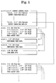
- Fig. 1 is a schematic diagram explaining the relationship of files contained in an MO disc according to the image output device as the first embodiment of the present invention.
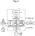
- Fig. 2 is a block diagram showing the structure of the image output device of the first embodiment.
- Fig. 3 is the first half of the flowchart of an automatic image output routine of the image output device.
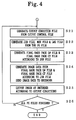
- Fig. 4 is the latter half of the flowchart of the automatic image output routine of the image output device.
- Fig. 5 is a structural diagram of a personal computer system embodying the present invention.
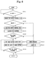
- Fig. 6 is a flowchart of an automatic image output process executed by the personal computer system.
- Fig. 7 is a structural diagram of a prior art image output system.
- an image output device of the present embodiment includes a main section 11, an MOD (magneto-optical disc) drive 12, a recorder 13 and a system disk unit 14.
- a general MOD drive can read data from and write data to an MO disc 25, but, in this embodiment, it is possible to use an MOD reader which cannot write data on the MO disc 25.
- the MOD drive 12 is equipped with an MOD detector 15 (the media detector) which detects that an MO disc 25 is set in the MOD drive 12.
- the recorder 13 outputs an image onto a film according to image data supplied from the later-described output controller 20.
- the output conditions of the recorder 13 of the present embodiment can be set by sending external command signals to the recorder 13.
- the system disk unit 14 may include one or several hard disk units, or a non-volatile semiconductor memory unit can be used instead of the hard disk.
- the main section 11 includes an interface 18 for the MOD drive 12, a calculation unit 19, an output controller 20 and another interface 21 for the system disk unit 14, all of which are interconnected with a data bus 23 for transmitting material data and layout data.
- the MOD interface 18 converts the format of data read out from an MO disc 25 to another format adapted to the main section 11.
- the signal from the MOD detector 15 is sent to the later-described system controller 17 via the MOD interface 18.
- the calculation unit 19 processes the material data and the layout data read out from the MO disc 25 and generates data of a final base page. Based on the data of the final base page, the output controller 20 generates data (image data) adapted to the recorder 13.
- the main section 11 further includes a system controller 17 and a console 16 which consists of a keyboard and a display.
- the MOD interface 18, the calculation unit 19 and the output controller 20 are connected to the system controller 17 with a control bus 22 for transmitting command signals.
- the necessary data and the predetermined manners of storage in an MO disc 25 for an automatic image outputting are explained referring to Fig. 1.
- the material data includes vector data (LW data) representing letters, lines, etc. and pixel data (CT data) representing photographs, etc.
- LW data is contained in a LW file or in plural LW files
- CT data is contained in a CT file or in plural CT files.
- the name of the LW file is given an extension of ".LW” (as "AAA.LW”) and the names of the CT files are given an extension of ".CT” (as "AAA1.CT” and "AAA2.CT”).
- the layout data representing the layout of the material (letters, lines, photographs, etc.) in the page must be stored in the MO disc 25.
- the layout data is contained in a PG file whose name is given an extension of ".PG” (as "AAA.PG” and "ZZZ.PG” in Fig. 1).
- a page (which corresponds to a piece of film in this case) to be outputted requires one PG file, and an MO disc 25 can store plural PG files to output plural pages.
- the PG file contains the names of the LW files and CT files of the material data constituting the page.
- the PG file may further contain vector data representing lines and linear drawings.
- the MO disc 25 used in the image output device of the present embodiment for the automatic image outputting must store an output control file having a predetermined name, e.g., "AUTOOUT" in Fig. 1.
- the output control file contains the name or names of the PG file or files corresponding to the page or pages to be outputted on a film or films.
- the output control file may further contain data of the output conditions of the recorder 13 (e.g., line-frequency and angle of the screen used to output the CT data on the film).
- the output control file does not contain the data of the output conditions, the conditions previously set at the recorder 13 are used or preset standard (default) conditions are used.
- the data of the output conditions can be contained in a separate file (output condition file), in which case the output control file contains the name of the output condition file.
- step S1 the system controller 17 waits until an MO disc 25 is set in the MOD drive 12 (step S1).
- step S2 the predetermined directory area of the MO disc 25 is searched.
- step S3 the predetermined name of the output control file ("AUTOOUT" in this case) exists in the directory area.
- step S15 a preset error message is presented on the display of the console 16 and the MO disc 25 is ejected from the MOD drive 12 (step S16).
- the output control file “AUTOOUT” is loaded from the MO disc 25 to the internal memory (RAM in the system controller 17) or to the system disk unit 14 at step S4, and the contents of the file “AUTOOUT” are examined at step S5.
- the output control file “AUTOOUT” contains one or plural PG filenames (n filenames from "AAA.PG” to "ZZZ.PG” in the case of Fig. 1).
- the system controller 17 judges at step S6 whether all the PG files "AAA.PG” to "ZZZ.PG” whose filenames are described in the output control file exist in the MO disc 25. When any of the PG files described in the output control file is missing in the MO disc 25, the process proceeds to steps S15 and S16 to present an appropriate error message and to eject the MO disc 25.
- step S21 the output conditions of the recorder 13 for the first page is read out from the output control file and an output condition file is created containing the data of the output conditions. Then a JOB file, an MSK file, and (if applicable) an LW2 file are created from the PG file corresponding to the first page (step S22). The LW2 file is combined with the LW files designated by the PG file to create a final base page LW file (step S23). The MSK file is used to create a final base page CT file with the CT files designated by the JOB file (step S23).
- the output controller 20 reads the output condition file and sets the recorder 13 according to the data contained therein. Then the output controller 20 retrieves LW data from the final base page LW file and CT data from the final base page CT file both stored in the system disk unit 14, and combines the LW data and the CT data to create data (image data) representing the image of the page.
- the image data is sent from the output controller 20 to the recorder 13, where the image data is outputted onto a film according to the output conditions (step S24).
- the output control file does not include data of the output conditions, previously set (through the console 16 or directly on the recorder 13) output conditions (the default output conditions) are used. Thus a reproduction film (i.e., ready to be used in producing a printing plate) of the first page is produced by the recorder 13.
- step S25 When the outputting of the first page is thus finished, it is then judged at step S25 whether all the PG files (n files in this case) have been processed. When any of the PG files remain unprocessed, the process returns to step S21 to repeat the above described automatic image outputting process. When all the PG files designated by the output control file "AUTOOUT" are finished, the present program ends.
- the filename of the PG file stored in the output control file corresponds to the designating data, because the location of PG file can be determined by referring to the directory area of the MO disk with the name of the PG file, and the location of the LW files and CT files (the material files) can be determined by again referring to the directory area of the MO disc with their names.
- the second embodiment of the present invention is an automatic image output system using a general data processing device such as a personal computer or a work station.
- a personal computer that can handle a page description language (PDL) is used for outputting the image of a page.
- a page description language (PDL) is a computer language for describing an outputting format of data, and one of the well known page descriptive languages is the PostScript (trade name of Adobe Systems, Inc.).
- the system of the present embodiment includes, as shown in Fig. 5: a personal computer 32, a floppy disk drive (FDD) 31 and an image setter 33.
- the floppy disk drive (FDD) can be replaced by an MOD (magneto-optical disc) drive.
- the layout data as well as the material data (including vector data and pixel data) of a page are both contained in a file (hereinafter it is referred to as a PDL file).
- PDL files corresponding to respective pages should be previously stored in a floppy disk (FD) 35 (or in an MO disc), and further an output control file having a preset name (e.g., "AUTOOUT" must be stored in the floppy disk (FD) 35.
- the output control file contains the data of the names of the PDL files and the data of the output conditions corresponding to the respective PDL files. As described above, it is possible to store the data of the output conditions in a separate file (output condition file) and to store the name of the output condition file in the output control file.
- the image output program as shown in Fig. 6 is executed.
- the personal computer 32 waits at step S31 for a floppy disk (FD) 35 to be inserted in the floppy disk drive (FDD) 31.
- a floppy disk (FD) 35 is inserted, the directory area of the floppy disk (FD) 35 is searched at step S32 to find the preset name ("AUTOOUT") of the output control file.
- the preset filename is not found at step S33, an appropriate error message is shown on a display of the personal computer 32 at step S40 and the floppy disk (FD) 35 is ejected from the floppy disk drive (FDD) 31.
- the output control file is read out from the floppy disk (FD) 35 at step S34.
- the contents of the output control file are examined at step S35 to get the name or names of the PDL files, and data of the output conditions (or alternatively the name of the file containing the data of the output conditions) of the image setter 33.
- the image setter 33 is set at the output conditions (e.g., line frequency and angle of the screen, etc.) as described in the output control file or, if applicable, referring to the output condition file. It is possible at step S36 not to stop processing and to continue processing by adopting the output conditions predetermined by the system (default conditions) or preset to the image setter 33 when no output condition data exists in the output control file or output condition file is missing in the floppy disk (FD) 35. Then the first PDL file is read out from the floppy disk (FD) 35 at step S38 and the PDL program contained therein is sent to the image setter 33.
- the output conditions e.g., line frequency and angle of the screen, etc.
- the image setter 33 outputs the image of the page on a sheet of paper or on a film according to the PDL program describing the page.
- the first PDL file is finished, it is judged at step S39 whether any PDL file remains unprocessed in the floppy disk (FD) 35.
- steps S37 and S38 are repeated until all the PDL files are finished outputting.
- a high-speed storage unit e.g. a hard disk unit or a semiconductor storage device
- FD floppy disk
Landscapes
- Engineering & Computer Science (AREA)
- Theoretical Computer Science (AREA)
- Human Computer Interaction (AREA)
- Physics & Mathematics (AREA)
- General Engineering & Computer Science (AREA)
- General Physics & Mathematics (AREA)
- Processing Or Creating Images (AREA)
- Preparing Plates And Mask In Photomechanical Process (AREA)
- Information Retrieval, Db Structures And Fs Structures Therefor (AREA)
Applications Claiming Priority (2)
| Application Number | Priority Date | Filing Date | Title |
|---|---|---|---|
| JP35412292A JP2803062B2 (ja) | 1992-12-14 | 1992-12-14 | 画像出力装置 |
| JP354122/92 | 1992-12-14 |
Publications (2)
| Publication Number | Publication Date |
|---|---|
| EP0603714A1 true EP0603714A1 (de) | 1994-06-29 |
| EP0603714B1 EP0603714B1 (de) | 1998-08-19 |
Family
ID=18435444
Family Applications (1)
| Application Number | Title | Priority Date | Filing Date |
|---|---|---|---|
| EP93120158A Expired - Lifetime EP0603714B1 (de) | 1992-12-14 | 1993-12-14 | Verfahren und Gerät für die automatische Datenausgabe einer Seite |
Country Status (4)
| Country | Link |
|---|---|
| US (1) | US5451111A (de) |
| EP (1) | EP0603714B1 (de) |
| JP (1) | JP2803062B2 (de) |
| DE (1) | DE69320450T2 (de) |
Cited By (8)
| Publication number | Priority date | Publication date | Assignee | Title |
|---|---|---|---|---|
| WO1997006481A1 (en) * | 1995-08-07 | 1997-02-20 | T/R Systems | Virtual single printer engine with software rip |
| US5940186A (en) * | 1994-01-13 | 1999-08-17 | T/R Systems, Inc. | Multiple printer module electrophotographic printing device |
| US6035103A (en) * | 1995-08-07 | 2000-03-07 | T/R Systems | Color correction for multiple print engine system with half tone and bi-level printing |
| US6707563B1 (en) | 1999-01-11 | 2004-03-16 | T/R Systems | Multiple print engine with error handling capability |
| US6850335B1 (en) | 1996-08-16 | 2005-02-01 | Electronics For Imaging, Inc. | Method and apparatus for distributing pages to individual print engines in a multiple print engine |
| US6977752B1 (en) | 1995-08-07 | 2005-12-20 | Electronics For Imaging, Inc. | Method and apparatus for determining toner level in electrophotographic print engines |
| US7027187B1 (en) | 1995-08-07 | 2006-04-11 | Electronics For Imaging, Inc. | Real time calibration of a marking engine in a print system |
| US7046391B1 (en) | 1995-08-07 | 2006-05-16 | Electronics For Imaging, Inc. | Method and apparatus for providing a color-balanced multiple print engine |
Families Citing this family (6)
| Publication number | Priority date | Publication date | Assignee | Title |
|---|---|---|---|---|
| US6243172B1 (en) | 1995-01-18 | 2001-06-05 | Varis Corporation | Method and system for merging variable text and images into bitmaps defined by a page description language |
| US5729665A (en) | 1995-01-18 | 1998-03-17 | Varis Corporation | Method of utilizing variable data fields with a page description language |
| US7302438B1 (en) | 1997-07-18 | 2007-11-27 | Tesseron Ltd. | Method and system for flowing data to an arbitrary path defined by a page description language |
| US7315979B1 (en) | 1998-11-09 | 2008-01-01 | Tesseron Ltd. | Method and system for dynamic flowing data to an arbitrary path defined by a page description language |
| JP2001117783A (ja) | 1999-08-10 | 2001-04-27 | Seiko Epson Corp | プログラム起動システム及びプログラム起動制御方法 |
| US8904284B2 (en) | 2011-03-01 | 2014-12-02 | Apple Inc. | Object placeholders in electronic documents |
Citations (2)
| Publication number | Priority date | Publication date | Assignee | Title |
|---|---|---|---|---|
| US5025398A (en) * | 1990-05-21 | 1991-06-18 | Storage Technology Corporation | Data stream independent printer |
| EP0479494A2 (de) * | 1990-09-28 | 1992-04-08 | Xerox Corporation | Verfahren zum Drucken von geordnetem Material |
Family Cites Families (3)
| Publication number | Priority date | Publication date | Assignee | Title |
|---|---|---|---|---|
| JPS6414661A (en) * | 1987-07-08 | 1989-01-18 | Dainippon Ink & Chemicals | Method and device for producing full color pagination |
| JPH01297770A (ja) * | 1988-05-26 | 1989-11-30 | Hitachi Ltd | 画像ファイリング装置のタイトル情報入力用帳票作成方法及び画像ファイリング方法 |
| JPH0774902B2 (ja) * | 1989-10-26 | 1995-08-09 | 大日本印刷株式会社 | 割付集版装置 |
-
1992
- 1992-12-14 JP JP35412292A patent/JP2803062B2/ja not_active Expired - Fee Related
-
1993
- 1993-12-08 US US08/164,035 patent/US5451111A/en not_active Expired - Lifetime
- 1993-12-14 DE DE69320450T patent/DE69320450T2/de not_active Expired - Fee Related
- 1993-12-14 EP EP93120158A patent/EP0603714B1/de not_active Expired - Lifetime
Patent Citations (2)
| Publication number | Priority date | Publication date | Assignee | Title |
|---|---|---|---|---|
| US5025398A (en) * | 1990-05-21 | 1991-06-18 | Storage Technology Corporation | Data stream independent printer |
| EP0479494A2 (de) * | 1990-09-28 | 1992-04-08 | Xerox Corporation | Verfahren zum Drucken von geordnetem Material |
Non-Patent Citations (1)
| Title |
|---|
| "PRINTER CONTROLLER ICS TAKE ON PDL BOTLENECK", COMPUTER DESIGN, vol. 27, no. 13, July 1988 (1988-07-01), LITTLETON, MASSACHUSETTS US, pages 26 - 30 * |
Cited By (24)
| Publication number | Priority date | Publication date | Assignee | Title |
|---|---|---|---|---|
| US5940186A (en) * | 1994-01-13 | 1999-08-17 | T/R Systems, Inc. | Multiple printer module electrophotographic printing device |
| US7046391B1 (en) | 1995-08-07 | 2006-05-16 | Electronics For Imaging, Inc. | Method and apparatus for providing a color-balanced multiple print engine |
| US7301665B2 (en) | 1995-08-07 | 2007-11-27 | Electronics For Imaging, Inc. | Method and apparatus for determining toner level in electrophotographic print engines |
| US6219155B1 (en) | 1995-08-07 | 2001-04-17 | T/R Systems | Color correction of contone images in a multiple print engine system |
| US6271937B1 (en) | 1995-08-07 | 2001-08-07 | Peter A. Zuber | Color correction of dot linearities in multiple print engine system |
| US6606165B1 (en) | 1995-08-07 | 2003-08-12 | T/R Systems, Inc. | Method and apparatus for routing pages to printers in a multi-print engine as a function of print job parameters |
| US6636326B1 (en) | 1995-08-07 | 2003-10-21 | T/R Systems | Method for calibrating a color marking engine for halftone operation |
| US6657741B1 (en) | 1995-08-07 | 2003-12-02 | Tr Systems, Inc. | Multiple print engine system with selectively distributed ripped pages |
| US7095528B2 (en) | 1995-08-07 | 2006-08-22 | Electronics For Imaging, Inc. | Apparatus and methods for duplex printing in multiple print engine systems |
| WO1997006481A1 (en) * | 1995-08-07 | 1997-02-20 | T/R Systems | Virtual single printer engine with software rip |
| US6977752B1 (en) | 1995-08-07 | 2005-12-20 | Electronics For Imaging, Inc. | Method and apparatus for determining toner level in electrophotographic print engines |
| US6035103A (en) * | 1995-08-07 | 2000-03-07 | T/R Systems | Color correction for multiple print engine system with half tone and bi-level printing |
| US7791777B2 (en) | 1995-08-07 | 2010-09-07 | Electronics For Imaging, Inc. | Method and apparatus for providing a color-balanced multiple print engine |
| US7532347B2 (en) | 1995-08-07 | 2009-05-12 | Electronics For Imaging, Inc. | Methods and apparatus for routing pages to printers in a multi-print engine as a function of print job parameters |
| US7116444B2 (en) | 1995-08-07 | 2006-10-03 | Electronics For Imaging, Inc. | Method and apparatus for determining toner level in electrophotographic print engines |
| US7206082B2 (en) | 1995-08-07 | 2007-04-17 | Electronics For Imaging, Inc. | Method and apparatus for routing pages to printers in a multi-print engine as a function of print job parameters |
| US7301671B2 (en) | 1995-08-07 | 2007-11-27 | Electronics For Imaging, Inc. | Method for calibrating a color marking engine for halftone operation |
| US7027187B1 (en) | 1995-08-07 | 2006-04-11 | Electronics For Imaging, Inc. | Real time calibration of a marking engine in a print system |
| US7342686B2 (en) | 1995-08-07 | 2008-03-11 | Electronics For Imaging, Inc. | Method and apparatus for providing a color-balanced multiple print engine |
| US7349124B2 (en) | 1995-08-07 | 2008-03-25 | Electronics For Imaging, Inc. | Methods and apparatus for real time calibration of a marking engine in a print system |
| US7471403B2 (en) | 1995-08-07 | 2008-12-30 | Electronics For Imaging, Inc. | Apparatus and methods for selectively distributing print pages in multiple print engine systems |
| US7489422B2 (en) | 1995-08-07 | 2009-02-10 | Electronics For Imaging, Inc. | Methods and apparatus for real time calibration of a print system marking engine |
| US6850335B1 (en) | 1996-08-16 | 2005-02-01 | Electronics For Imaging, Inc. | Method and apparatus for distributing pages to individual print engines in a multiple print engine |
| US6707563B1 (en) | 1999-01-11 | 2004-03-16 | T/R Systems | Multiple print engine with error handling capability |
Also Published As
| Publication number | Publication date |
|---|---|
| JP2803062B2 (ja) | 1998-09-24 |
| US5451111A (en) | 1995-09-19 |
| DE69320450D1 (de) | 1998-09-24 |
| EP0603714B1 (de) | 1998-08-19 |
| JPH06180495A (ja) | 1994-06-28 |
| DE69320450T2 (de) | 1998-12-24 |
Similar Documents
| Publication | Publication Date | Title |
|---|---|---|
| EP0603714B1 (de) | Verfahren und Gerät für die automatische Datenausgabe einer Seite | |
| EP0274571B1 (de) | Elektronisches Gerät zum Aktenablegen | |
| US4949188A (en) | Image processing apparatus | |
| JP3101363B2 (ja) | 等価性インジケータを備えたユーザによる規定が可能なフォント置換装置 | |
| EP1229723A2 (de) | Bildausgabesteuergerät | |
| EP0843284B1 (de) | Verfahren und System für Druckbilderzeugung und Aufzeichnungsmaterial | |
| JP2000242463A (ja) | 印刷システム | |
| US7305620B1 (en) | Method and apparatus for previewing print data and recording media thereof | |
| CN100577432C (zh) | 图像形成设备 | |
| US7606446B2 (en) | Apparatus, method, or storage medium for image processing | |
| US5572499A (en) | Image processing apparatus for storing image data in storage medium and/or for reproducing image stored in storage medium | |
| JPH10222319A (ja) | 印刷装置及び印刷制御方法 | |
| JP3458001B2 (ja) | 画像ファイル装置 | |
| JP3912952B2 (ja) | 画像再生装置および方法 | |
| JPH05108732A (ja) | 電子画像アルバム装置 | |
| JP3161744B2 (ja) | 情報処理装置 | |
| JP3234800B2 (ja) | 画像検査システム | |
| JP2000123008A (ja) | 文書処理装置及び方法 | |
| JP2885761B2 (ja) | 連続紙ページプリンタシステム | |
| JPH0771181B2 (ja) | 記録方法 | |
| JP2000132367A (ja) | デジタル画像形成装置 | |
| JPH1011038A (ja) | 情報処理装置及びインターフェース装置及び画像出力制御方法 | |
| JP2001270162A (ja) | 画像形成装置および画像データの出力方法 | |
| US20060187494A1 (en) | Image processing method, image processing apparatus, and control program for image processing apparatus | |
| JPH0329055A (ja) | 文書作成装置 |
Legal Events
| Date | Code | Title | Description |
|---|---|---|---|
| PUAI | Public reference made under article 153(3) epc to a published international application that has entered the european phase |
Free format text: ORIGINAL CODE: 0009012 |
|
| AK | Designated contracting states |
Kind code of ref document: A1 Designated state(s): DE FR GB |
|
| 17P | Request for examination filed |
Effective date: 19941001 |
|
| GRAG | Despatch of communication of intention to grant |
Free format text: ORIGINAL CODE: EPIDOS AGRA |
|
| 17Q | First examination report despatched |
Effective date: 19971218 |
|
| GRAG | Despatch of communication of intention to grant |
Free format text: ORIGINAL CODE: EPIDOS AGRA |
|
| GRAH | Despatch of communication of intention to grant a patent |
Free format text: ORIGINAL CODE: EPIDOS IGRA |
|
| GRAH | Despatch of communication of intention to grant a patent |
Free format text: ORIGINAL CODE: EPIDOS IGRA |
|
| GRAA | (expected) grant |
Free format text: ORIGINAL CODE: 0009210 |
|
| AK | Designated contracting states |
Kind code of ref document: B1 Designated state(s): DE FR GB |
|
| PG25 | Lapsed in a contracting state [announced via postgrant information from national office to epo] |
Ref country code: FR Free format text: LAPSE BECAUSE OF FAILURE TO SUBMIT A TRANSLATION OF THE DESCRIPTION OR TO PAY THE FEE WITHIN THE PRESCRIBED TIME-LIMIT Effective date: 19980819 |
|
| REF | Corresponds to: |
Ref document number: 69320450 Country of ref document: DE Date of ref document: 19980924 |
|
| EN | Fr: translation not filed | ||
| PLBE | No opposition filed within time limit |
Free format text: ORIGINAL CODE: 0009261 |
|
| STAA | Information on the status of an ep patent application or granted ep patent |
Free format text: STATUS: NO OPPOSITION FILED WITHIN TIME LIMIT |
|
| 26N | No opposition filed | ||
| REG | Reference to a national code |
Ref country code: GB Ref legal event code: IF02 |
|
| PGFP | Annual fee paid to national office [announced via postgrant information from national office to epo] |
Ref country code: DE Payment date: 20081211 Year of fee payment: 16 |
|
| PGFP | Annual fee paid to national office [announced via postgrant information from national office to epo] |
Ref country code: GB Payment date: 20081210 Year of fee payment: 16 |
|
| GBPC | Gb: european patent ceased through non-payment of renewal fee |
Effective date: 20091214 |
|
| PG25 | Lapsed in a contracting state [announced via postgrant information from national office to epo] |
Ref country code: DE Free format text: LAPSE BECAUSE OF NON-PAYMENT OF DUE FEES Effective date: 20100701 |
|
| PG25 | Lapsed in a contracting state [announced via postgrant information from national office to epo] |
Ref country code: GB Free format text: LAPSE BECAUSE OF NON-PAYMENT OF DUE FEES Effective date: 20091214 |