EP0603750B1 - Target für magnetooptische Aufzeichnungsmedien und Verfahren zu seiner Herstellung - Google Patents
Target für magnetooptische Aufzeichnungsmedien und Verfahren zu seiner Herstellung Download PDFInfo
- Publication number
- EP0603750B1 EP0603750B1 EP93120332A EP93120332A EP0603750B1 EP 0603750 B1 EP0603750 B1 EP 0603750B1 EP 93120332 A EP93120332 A EP 93120332A EP 93120332 A EP93120332 A EP 93120332A EP 0603750 B1 EP0603750 B1 EP 0603750B1
- Authority
- EP
- European Patent Office
- Prior art keywords
- powder
- particles
- target
- average diameter
- iron
- Prior art date
- Legal status (The legal status is an assumption and is not a legal conclusion. Google has not performed a legal analysis and makes no representation as to the accuracy of the status listed.)
- Expired - Lifetime
Links
- 238000004519 manufacturing process Methods 0.000 title claims description 8
- 239000000843 powder Substances 0.000 claims description 123
- 229910052751 metal Inorganic materials 0.000 claims description 83
- 239000002184 metal Substances 0.000 claims description 83
- 239000002245 particle Substances 0.000 claims description 81
- 229910045601 alloy Inorganic materials 0.000 claims description 30
- 239000000956 alloy Substances 0.000 claims description 30
- 229910052761 rare earth metal Inorganic materials 0.000 claims description 26
- 230000005496 eutectics Effects 0.000 claims description 25
- 150000002910 rare earth metals Chemical class 0.000 claims description 25
- 239000000203 mixture Substances 0.000 claims description 21
- 230000005415 magnetization Effects 0.000 claims description 16
- 238000000034 method Methods 0.000 claims description 14
- 239000011812 mixed powder Substances 0.000 claims description 13
- 229910052758 niobium Inorganic materials 0.000 claims description 13
- 238000005245 sintering Methods 0.000 claims description 13
- 239000011159 matrix material Substances 0.000 claims description 9
- 229910052719 titanium Inorganic materials 0.000 claims description 9
- 229910052782 aluminium Inorganic materials 0.000 claims description 8
- 229910052802 copper Inorganic materials 0.000 claims description 8
- 229910052804 chromium Inorganic materials 0.000 claims description 7
- 229910052697 platinum Inorganic materials 0.000 claims description 7
- 238000010791 quenching Methods 0.000 claims description 7
- 239000007788 liquid Substances 0.000 claims description 5
- 239000000155 melt Substances 0.000 claims description 4
- 238000002156 mixing Methods 0.000 claims description 4
- 230000007797 corrosion Effects 0.000 description 29
- 238000005260 corrosion Methods 0.000 description 29
- 230000035699 permeability Effects 0.000 description 29
- 239000010409 thin film Substances 0.000 description 23
- 239000012071 phase Substances 0.000 description 20
- 238000004544 sputter deposition Methods 0.000 description 20
- 150000002739 metals Chemical class 0.000 description 17
- 229910001257 Nb alloy Inorganic materials 0.000 description 14
- 229910052742 iron Inorganic materials 0.000 description 14
- 229910000640 Fe alloy Inorganic materials 0.000 description 12
- 230000000052 comparative effect Effects 0.000 description 12
- 238000009826 distribution Methods 0.000 description 12
- 230000005291 magnetic effect Effects 0.000 description 12
- 230000007423 decrease Effects 0.000 description 11
- 229910017060 Fe Cr Inorganic materials 0.000 description 9
- 229910002544 Fe-Cr Inorganic materials 0.000 description 9
- UPHIPHFJVNKLMR-UHFFFAOYSA-N chromium iron Chemical compound [Cr].[Fe] UPHIPHFJVNKLMR-UHFFFAOYSA-N 0.000 description 9
- 229910017061 Fe Co Inorganic materials 0.000 description 8
- 230000004907 flux Effects 0.000 description 8
- 238000011282 treatment Methods 0.000 description 8
- QVGXLLKOCUKJST-UHFFFAOYSA-N atomic oxygen Chemical compound [O] QVGXLLKOCUKJST-UHFFFAOYSA-N 0.000 description 7
- 230000001186 cumulative effect Effects 0.000 description 7
- 238000001513 hot isostatic pressing Methods 0.000 description 7
- 239000001301 oxygen Substances 0.000 description 7
- 229910052760 oxygen Inorganic materials 0.000 description 7
- 229910052771 Terbium Inorganic materials 0.000 description 6
- 230000005294 ferromagnetic effect Effects 0.000 description 6
- 229910000765 intermetallic Inorganic materials 0.000 description 6
- 239000000758 substrate Substances 0.000 description 6
- XKRFYHLGVUSROY-UHFFFAOYSA-N Argon Chemical compound [Ar] XKRFYHLGVUSROY-UHFFFAOYSA-N 0.000 description 4
- 238000005275 alloying Methods 0.000 description 4
- 239000002775 capsule Substances 0.000 description 4
- 230000003247 decreasing effect Effects 0.000 description 4
- 238000005259 measurement Methods 0.000 description 4
- 238000002844 melting Methods 0.000 description 4
- 230000008018 melting Effects 0.000 description 4
- 238000009689 gas atomisation Methods 0.000 description 3
- 239000002923 metal particle Substances 0.000 description 3
- 230000001105 regulatory effect Effects 0.000 description 3
- 229910000831 Steel Inorganic materials 0.000 description 2
- 229910052786 argon Inorganic materials 0.000 description 2
- 230000002542 deteriorative effect Effects 0.000 description 2
- 230000000694 effects Effects 0.000 description 2
- 238000007731 hot pressing Methods 0.000 description 2
- 238000003703 image analysis method Methods 0.000 description 2
- 229910052759 nickel Inorganic materials 0.000 description 2
- 230000003287 optical effect Effects 0.000 description 2
- 230000003647 oxidation Effects 0.000 description 2
- 238000007254 oxidation reaction Methods 0.000 description 2
- 230000008569 process Effects 0.000 description 2
- 230000000171 quenching effect Effects 0.000 description 2
- 239000010959 steel Substances 0.000 description 2
- 229910001362 Ta alloys Inorganic materials 0.000 description 1
- 229910001069 Ti alloy Inorganic materials 0.000 description 1
- 230000002730 additional effect Effects 0.000 description 1
- 229910002056 binary alloy Inorganic materials 0.000 description 1
- 230000015572 biosynthetic process Effects 0.000 description 1
- 238000007664 blowing Methods 0.000 description 1
- 230000008859 change Effects 0.000 description 1
- 238000006243 chemical reaction Methods 0.000 description 1
- 239000012141 concentrate Substances 0.000 description 1
- 230000001276 controlling effect Effects 0.000 description 1
- 230000006866 deterioration Effects 0.000 description 1
- 230000003628 erosive effect Effects 0.000 description 1
- 239000006023 eutectic alloy Substances 0.000 description 1
- 230000005307 ferromagnetism Effects 0.000 description 1
- 239000010419 fine particle Substances 0.000 description 1
- 239000007789 gas Substances 0.000 description 1
- 239000011521 glass Substances 0.000 description 1
- 238000010438 heat treatment Methods 0.000 description 1
- 230000006698 induction Effects 0.000 description 1
- 239000011261 inert gas Substances 0.000 description 1
- 239000007791 liquid phase Substances 0.000 description 1
- 238000001755 magnetron sputter deposition Methods 0.000 description 1
- 238000009828 non-uniform distribution Methods 0.000 description 1
- 229910052763 palladium Inorganic materials 0.000 description 1
- 238000010587 phase diagram Methods 0.000 description 1
- 239000004417 polycarbonate Substances 0.000 description 1
- 229920000515 polycarbonate Polymers 0.000 description 1
- 238000010298 pulverizing process Methods 0.000 description 1
- 239000011347 resin Substances 0.000 description 1
- 229920005989 resin Polymers 0.000 description 1
- 238000005096 rolling process Methods 0.000 description 1
- 238000005477 sputtering target Methods 0.000 description 1
- 229910052715 tantalum Inorganic materials 0.000 description 1
- 238000009827 uniform distribution Methods 0.000 description 1
- 230000003313 weakening effect Effects 0.000 description 1
Images


Classifications
-
- G—PHYSICS
- G11—INFORMATION STORAGE
- G11B—INFORMATION STORAGE BASED ON RELATIVE MOVEMENT BETWEEN RECORD CARRIER AND TRANSDUCER
- G11B5/00—Recording by magnetisation or demagnetisation of a record carrier; Reproducing by magnetic means; Record carriers therefor
- G11B5/62—Record carriers characterised by the selection of the material
- G11B5/64—Record carriers characterised by the selection of the material comprising only the magnetic material without bonding agent
- G11B5/65—Record carriers characterised by the selection of the material comprising only the magnetic material without bonding agent characterised by its composition
-
- C—CHEMISTRY; METALLURGY
- C23—COATING METALLIC MATERIAL; COATING MATERIAL WITH METALLIC MATERIAL; CHEMICAL SURFACE TREATMENT; DIFFUSION TREATMENT OF METALLIC MATERIAL; COATING BY VACUUM EVAPORATION, BY SPUTTERING, BY ION IMPLANTATION OR BY CHEMICAL VAPOUR DEPOSITION, IN GENERAL; INHIBITING CORROSION OF METALLIC MATERIAL OR INCRUSTATION IN GENERAL
- C23C—COATING METALLIC MATERIAL; COATING MATERIAL WITH METALLIC MATERIAL; SURFACE TREATMENT OF METALLIC MATERIAL BY DIFFUSION INTO THE SURFACE, BY CHEMICAL CONVERSION OR SUBSTITUTION; COATING BY VACUUM EVAPORATION, BY SPUTTERING, BY ION IMPLANTATION OR BY CHEMICAL VAPOUR DEPOSITION, IN GENERAL
- C23C14/00—Coating by vacuum evaporation, by sputtering or by ion implantation of the coating forming material
- C23C14/22—Coating by vacuum evaporation, by sputtering or by ion implantation of the coating forming material characterised by the process of coating
- C23C14/34—Sputtering
- C23C14/3407—Cathode assembly for sputtering apparatus, e.g. Target
- C23C14/3414—Metallurgical or chemical aspects of target preparation, e.g. casting, powder metallurgy
-
- G—PHYSICS
- G11—INFORMATION STORAGE
- G11B—INFORMATION STORAGE BASED ON RELATIVE MOVEMENT BETWEEN RECORD CARRIER AND TRANSDUCER
- G11B11/00—Recording on or reproducing from the same record carrier wherein for these two operations the methods are covered by different main groups of groups G11B3/00 - G11B7/00 or by different subgroups of group G11B9/00; Record carriers therefor
- G11B11/10—Recording on or reproducing from the same record carrier wherein for these two operations the methods are covered by different main groups of groups G11B3/00 - G11B7/00 or by different subgroups of group G11B9/00; Record carriers therefor using recording by magnetic means or other means for magnetisation or demagnetisation of a record carrier, e.g. light induced spin magnetisation; Demagnetisation by thermal or stress means in the presence or not of an orienting magnetic field
- G11B11/105—Recording on or reproducing from the same record carrier wherein for these two operations the methods are covered by different main groups of groups G11B3/00 - G11B7/00 or by different subgroups of group G11B9/00; Record carriers therefor using recording by magnetic means or other means for magnetisation or demagnetisation of a record carrier, e.g. light induced spin magnetisation; Demagnetisation by thermal or stress means in the presence or not of an orienting magnetic field using a beam of light or a magnetic field for recording by change of magnetisation and a beam of light for reproducing, i.e. magneto-optical, e.g. light-induced thermomagnetic recording, spin magnetisation recording, Kerr or Faraday effect reproducing
- G11B11/10582—Record carriers characterised by the selection of the material or by the structure or form
-
- G—PHYSICS
- G11—INFORMATION STORAGE
- G11B—INFORMATION STORAGE BASED ON RELATIVE MOVEMENT BETWEEN RECORD CARRIER AND TRANSDUCER
- G11B11/00—Recording on or reproducing from the same record carrier wherein for these two operations the methods are covered by different main groups of groups G11B3/00 - G11B7/00 or by different subgroups of group G11B9/00; Record carriers therefor
- G11B11/10—Recording on or reproducing from the same record carrier wherein for these two operations the methods are covered by different main groups of groups G11B3/00 - G11B7/00 or by different subgroups of group G11B9/00; Record carriers therefor using recording by magnetic means or other means for magnetisation or demagnetisation of a record carrier, e.g. light induced spin magnetisation; Demagnetisation by thermal or stress means in the presence or not of an orienting magnetic field
- G11B11/105—Recording on or reproducing from the same record carrier wherein for these two operations the methods are covered by different main groups of groups G11B3/00 - G11B7/00 or by different subgroups of group G11B9/00; Record carriers therefor using recording by magnetic means or other means for magnetisation or demagnetisation of a record carrier, e.g. light induced spin magnetisation; Demagnetisation by thermal or stress means in the presence or not of an orienting magnetic field using a beam of light or a magnetic field for recording by change of magnetisation and a beam of light for reproducing, i.e. magneto-optical, e.g. light-induced thermomagnetic recording, spin magnetisation recording, Kerr or Faraday effect reproducing
- G11B11/10582—Record carriers characterised by the selection of the material or by the structure or form
- G11B11/10586—Record carriers characterised by the selection of the material or by the structure or form characterised by the selection of the material
- G11B11/10589—Details
-
- H—ELECTRICITY
- H01—ELECTRIC ELEMENTS
- H01F—MAGNETS; INDUCTANCES; TRANSFORMERS; SELECTION OF MATERIALS FOR THEIR MAGNETIC PROPERTIES
- H01F41/00—Apparatus or processes specially adapted for manufacturing or assembling magnets, inductances or transformers; Apparatus or processes specially adapted for manufacturing materials characterised by their magnetic properties
- H01F41/14—Apparatus or processes specially adapted for manufacturing or assembling magnets, inductances or transformers; Apparatus or processes specially adapted for manufacturing materials characterised by their magnetic properties for applying magnetic films to substrates
- H01F41/18—Apparatus or processes specially adapted for manufacturing or assembling magnets, inductances or transformers; Apparatus or processes specially adapted for manufacturing materials characterised by their magnetic properties for applying magnetic films to substrates by cathode sputtering
- H01F41/183—Sputtering targets therefor
-
- Y—GENERAL TAGGING OF NEW TECHNOLOGICAL DEVELOPMENTS; GENERAL TAGGING OF CROSS-SECTIONAL TECHNOLOGIES SPANNING OVER SEVERAL SECTIONS OF THE IPC; TECHNICAL SUBJECTS COVERED BY FORMER USPC CROSS-REFERENCE ART COLLECTIONS [XRACs] AND DIGESTS
- Y10—TECHNICAL SUBJECTS COVERED BY FORMER USPC
- Y10T—TECHNICAL SUBJECTS COVERED BY FORMER US CLASSIFICATION
- Y10T428/00—Stock material or miscellaneous articles
- Y10T428/12—All metal or with adjacent metals
- Y10T428/12014—All metal or with adjacent metals having metal particles
-
- Y—GENERAL TAGGING OF NEW TECHNOLOGICAL DEVELOPMENTS; GENERAL TAGGING OF CROSS-SECTIONAL TECHNOLOGIES SPANNING OVER SEVERAL SECTIONS OF THE IPC; TECHNICAL SUBJECTS COVERED BY FORMER USPC CROSS-REFERENCE ART COLLECTIONS [XRACs] AND DIGESTS
- Y10—TECHNICAL SUBJECTS COVERED BY FORMER USPC
- Y10T—TECHNICAL SUBJECTS COVERED BY FORMER US CLASSIFICATION
- Y10T428/00—Stock material or miscellaneous articles
- Y10T428/12—All metal or with adjacent metals
- Y10T428/12014—All metal or with adjacent metals having metal particles
- Y10T428/12028—Composite; i.e., plural, adjacent, spatially distinct metal components [e.g., layers, etc.]
-
- Y—GENERAL TAGGING OF NEW TECHNOLOGICAL DEVELOPMENTS; GENERAL TAGGING OF CROSS-SECTIONAL TECHNOLOGIES SPANNING OVER SEVERAL SECTIONS OF THE IPC; TECHNICAL SUBJECTS COVERED BY FORMER USPC CROSS-REFERENCE ART COLLECTIONS [XRACs] AND DIGESTS
- Y10—TECHNICAL SUBJECTS COVERED BY FORMER USPC
- Y10T—TECHNICAL SUBJECTS COVERED BY FORMER US CLASSIFICATION
- Y10T428/00—Stock material or miscellaneous articles
- Y10T428/12—All metal or with adjacent metals
- Y10T428/12014—All metal or with adjacent metals having metal particles
- Y10T428/1216—Continuous interengaged phases of plural metals, or oriented fiber containing
Definitions
- the present invention relates to a target for magneto-optical recording media mainly composed of rare earth metals and iron-group metals suitable for use in a magnetron-type sputtering apparatus, and a method for producing such a target.
- the magneto-optical disk is a type of magneto-optical recording media comprising a substrate made of a resin such as polycarbonate and a thin-film layer formed on the substrate by a sputtering method, the thin-film layer being made of an alloy of at least one rare earth metal and at least one iron-group metal such as an Tb-Fe-Co alloy. Writing and reading are conducted by utilizing a laser beam.
- Sputtering targets usable for the production of such magneto-optical recording media are required to provide a thin-film layers in which the concentrations of rare earth metals do not change from place to place; namely it is required that the targets have uniform rare earth metal distributions in a plane (in a lateral direction).
- the inventors previously proposed a target comprising a matrix phase composed of a eutectic structure consisting of at least one rare earth metal and at least one iron-group metal, and iron-group metal particles bonded to the matrix phase via a thin intermetallic compound phase, thereby having an increased uniformity in the in-plane distributions of rare earth metals, and good mechanical workability and sinterability (Japanese Patent Laid-Open No. 1-25977).
- a permanent magnet is disposed behind a target so that a magnetic flux leaks from a surface of the target to concentrate a high-density plasma in the vicinity of the target surface.
- the target for magneto-optical recording media as disclosed in Japanese Patent Laid-Open Nos. 1-25977 and 1-247571 show high permeability because their metal structures contain ferromagnetic iron-group metals. Accordingly, most magnetic flux generated from the permanent magnet behind the target forms a closed magnetic circuit passing though the interior of the target in the above-described magnetron-type sputtering apparatus. As a result, the magnetic flux leaking from the surface of the target decreases, resulting in a low film-forming speed and non-uniform erosion, which in turn lead to a low utilization factor of the target. Accordingly, the targets having the above structures fail to exhibit the desired performance of the magnetron-type sputtering apparatus.
- the problem of high permeability is also contemplated in DE-A-39 35 698.
- This document relates to a target for magneto-optical recording media having a specific structure composed of at least one rare earth metal, at least one specific additional element and at least one element selected from Co, Fe and Ni.
- an object of the present invention is to provide a target suitable for a magnetron-type sputtering apparatus without deteriorating the advantages of the targets of Japanese Patent Laid-Open Nos. 1-25977 and 1-247571, such as uniform thin-film composition and good machinability.
- Another object of the present invention is to provide a method for producing such a target.
- the inventors have found that by adding elements for improving the corrosion resistance of a thin-film layer in the form of an alloy with an iron-group metal, the saturation magnetization and permeability of the target can be reduced as compared with a case where each corrosion resistance-improving element is added separately.
- the inventors further have found that by controlling iron-group metal particles having ferromagnetism and alloy particles of iron-group metals and the above elements for improving the corrosion resistance of a thin-film layer such that their average diameter is restricted to 200 ⁇ m or less, the maximum permeability of the target can be lowered.
- the present invention has been completed based on these findings.
- the target for magneto-optical recording media is constituted by a sintered body having a microstructure having as a matrix phase a eutectic structure of at least one rare earth metal and at least one iron-group metal, in which first particles made of a pure iron-group metal or an alloy thereof and having an average diameter of 200 ⁇ m or less (hereinafter referred to as "particles I"), and second particles made of at least one metal selected from the group consisting of Ti, Al, Cu, Cr, Nb, Ta, Pd and Pt (hereinafter referred to as "corrosion resistance-improving metal") and at least one iron-group metal and having an average diameter of 200 ⁇ m or less (hereinafter referred to as "particles II”) are uniformly dispersed, the sintered body thereby having a maximum permeability of 25 or less.
- the method for producing a target for magneto-optical recording media comprises the steps of;
- the target of the present invention typically has a microstructure schematically shown in Fig. 3. Namely, the target of the present invention has a microstructure in which particles I and particles II each encircled by a thin bonding phase are uniformly dispersed in a matrix phase composed of a eutectic structure.
- utectic structure means a metal structure in which at least one rare earth metal and at least one iron-group metal exist in a proportion range from an intermetallic compound composition in which an atomic ratio of the rare earth metal to the iron-group metal is 1:2 to a composition in which the rare earth metal is less than 100 atomic %.
- the amount of Tb is 33.4 atomic % or more and less than 100 atomic %, preferably 45-75 atomic %.
- the eutectic structure of the target of the present invention is a fine structure consisting of an intermetallic compound and an ⁇ -rare earth metal phase. Such a fine structure functions to alleviate the non-uniformity of an angle at which rare earth metal particles are scattered from the target in the process of sputtering, thereby making uniform the distributions of the rare earth metals in the resulting thin-film layers.
- the particles I are made of a pure iron-group metal or an alloy thereof, and the particles II are made of an alloy of at least one corrosion resistance-improving metal and at least one iron-group metal.
- the amount of the particles I is preferably 5-30 weight %, and more preferably 7-20 weight % based on the target.
- the amount of the particles II is preferably 10-50 weight %, and more preferably 15-40 weight % based on the target.
- the maximum permeability of the target can be increased.
- the maximum diameter of the ferromagnetic particles I and particles II is preferably regulated to 150 ⁇ m or less.
- At least one metal selected from the group consisting of Ti, Al, Cu, Cr, Nb, Ta, Pd and Pt is added as the corrosion resistance-improving metal which functions to impart corrosion resistance to the resulting thin-film layer. Since the addition of too much corrosion resistance-improving metal would lead to the deterioration of magnetic properties of the resulting thin-film layer, the amount of the corrosion resistance-improving metal added is preferably 15 atomic % or less, and more preferably 2-8 atomic %, based on the target.
- These corrosion resistance-improving metals are added in the form of their alloys with at least one iron-group metal. This alloying provides, in addition to the above effect of decreasing the maximum permeability and the saturation magnetization, the following effects:
- the corrosion resistance-improving metal is less likely to be segregated in the target as compared with a case in which it is added in the form of pure metal powder, thereby making the in-plane distribution of corrosion resistance-improving metal uniform. Also, uneven distribution of corrosion resistance-improving metal in the thin-film layer formed from such a target can be avoided.
- Ti, Nb and Ta among the corrosion resistance-improving metals can be alloyed with at least one iron-group metal to provide eutectic alloys having low melting temperatures, the sinterability can be improved as compared with a case in which they are added in the form of pure metal powder.
- the particles I and the particles II dispersed in the target tend to form an intermetallic compound by reaction with the rare earth metals existing in the eutectic structure. Accordingly, it is necessary to suppress the formation of the intermetallic compound at such a degree that the eutectic structure necessary for keeping the distribution of the rare earth metal uniform is not destroyed.
- the bonding phase formed between the eutectic structure and the particles I and II is preferably 30 ⁇ m or less, and more preferably 10 ⁇ m or less.
- the target of the present invention may be produced by mixing powder having a eutectic structure formed from at least one rare earth metal and at least one iron-group metal by rapid quenching (powder A), powder made of a pure iron-group metal or an alloy thereof and having an average diameter of 200 ⁇ m or less (powder B), and powder made of at least one corrosion resistance-improving metal and at least one iron-group metal and having an average diameter of 200 ⁇ m or less (powder C), and pressure-sintering the resultant mixed powder at a temperature lower than a liquid phase-appearing temperature.
- binder B used herein generally means powder made of a pure iron-group metal such as Fe, Co, Ni alone, or an alloy of these iron-group metals such as an Fe-Co alloy.
- binder C used herein generally means alloy powder made of at least one corrosion resistance-improving metal selected from the group consisting of Ti, Al, Cu, Cr, Nb, Ta, Pd and Pt and at least one iron-group metal, such as an Fe-Cr alloy, an Fe-Nb alloy, an Fe-Ta alloy, an Fe-Cr-Ti alloy, etc.
- the average diameter of the powder A is preferably 125 ⁇ m or less, and more preferably 40-80 ⁇ m.
- the average diameter of the powder B is preferably 200 ⁇ m or less, more preferably 125 ⁇ m or less, and particularly 1-80 ⁇ m.
- the average diameter of the powder C is preferably 200 ⁇ m or less, more preferably 125 ⁇ m or less, and particularly 1-80 ⁇ m.
- the resultant target has a preferred microstructure in which ferromagnetic particles I formed from powder B and particles II formed from powder C are uniformly dispersed.
- magnetic flux passing through the target in the process of magnetron sputtering is extremely uniform, resulting in a uniformly sputtered thin-film layer.
- the starting powder preferably meets the requirement that each of powder A, powder B and powder C has an average diameter within 20% of tolerance relative to an average diameter of a mixture of powder A, powder B and powder C.
- each of powder A, powder B and powder C has an average diameter within 20% of tolerance relative to an average diameter of a mixture of powder A, powder B and powder C.
- a maximum permeability of the target is reduced as compared with a case in which the corrosion resistance-improving metals and iron-group metals are added in the form of separate powders.
- the decrease in maximum permeability by alloying appears to be due to the fact that the corrosion resistance-improving metal is replaced for the iron-group metal in a lattice, thereby weakening a ferromagnetic bonding.
- the saturation magnetization is also decreased by this alloying.
- the maximum permeability can be decreased by adding other metals, it is extremely efficient to add the corrosion resistance-improving metals because they function to improve the corrosion resistance of a target and decrease a maximum permeability thereof.
- the alloy powder C of at least one iron-group metal and at least one corrosion resistance-improving metal having a low melting point can be easily produced referring to its phase diagram, the optimum composition of powder C can easily be determined such that it shows a low melting point.
- the iron-group metal may be added in the form of pure metal powder or alloy powder of two or more iron-group metals to adjust the amounts of the iron-group metals in the target composition.
- the powder having a eutectic structure is obtained by rapid quenching, because the rapid-quenching treatment can provide a finer eutectic structure than a pulverization method. It is possible to regulate the oxygen content in the formed powder to 1,000 ppm or less in the rapid-quenching treatment. With such a low oxygen content, magnetic properties such as coercivity, Kerr rotation angle, etc. of the resulting thin-film layers can be improved and stabilized. Examples of such rapid-quenching treatments include a gas atomizing method, an electrode rotation method, a disc rotation method, etc.
- the sintering temperature is lower than a liquid phase-appearing temperature.
- the reason therefor is as follows: If the liquid phase appears in the course of sintering, intermetallic compounds are formed rapidly between the eutectic structure and the particles I of the iron-group metal and/or the particles II of the corrosion resistance-improving metal and the iron-group metal, thereby destroying the eutectic structure.
- the sintering temperature is selected to be slightly lower than the eutectic point of the rare earth metal and the iron-group metal. Specifically, the sintering temperature is lower than the liquid phase-appearing temperature (eutectic point) and preferably higher than 500 °C, for instance 600-850 °C.
- the pressure sintering can be conducted by a hot-isostatic pressing (HIP) method, a hot-pressing (HP) method, a hot-pack rolling method, etc.
- HIP hot-isostatic pressing
- HP hot-pressing
- a hot-pack rolling method etc.
- the sintering is preferably conducted in vacuum or in an inert gas atmosphere.
- the sintering time is preferably 0.5-5 hours, and more preferably 1-3 hours.
- the sintering pressure is preferably 98.1 - 147.2 MPa (1,000-1,500 kgf/cm 2 ).
- a target suitable for magnetron-type sputtering which has a maximum permeability of 25 or less, preferably 10 or less, and has a saturation magnetization (4 ⁇ Is) of preferably 1 T (10,000 G) or less, more preferably 0.9 T (9,000 G) or less.
- An additional effect by decreasing the maximum permeability is an increase in the amount of magnetic flux leaking from the target.
- the bonding phase is thin, and since the metal structure of the target is uniform, thin-film layers having good properties can be stably formed even after a long period of sputtering time, without deteriorating the mechanical strength of the target.
- Tb-Fe alloy (Tb: 67.4 atomic %, Fe: balance) was charged into a crucible equipped with a melt-dropping nozzle at the bottom thereof. After placing this crucible in a gas atomizing apparatus, the apparatus was evacuated to the order of 1.33 ⁇ 10 -4 hPa (10 -4 Torr), and the ingot was melted by high-frequency induction heating. When the melt temperature reached 1,200°C, the melt was dropped from the bottom of the apparatus though the nozzle while blowing a high-pressure argon gas from a gas-ejecting nozzle to produce gas-atomized Tb-Fe alloy powder.
- each of the Tb-Fe alloy powder, the pure Fe powder, the pure Co powder, and the Fe-Nb alloy powder was classified to provide six classes of powder having different particle sizes as shown in Table 1.
- an average diameter D 50 was measured by a sedimentation-type particle size measurement apparatus. No. Example Average diameter D 50 ( ⁇ m) Fe Co Fe-Nb Tb-Fe Mixture 1 190 200 190 200 195 2 120 130 120 120 123 3 95 95 85 90 90 4 65 60 60 55 60 5 30 30 35 35 33 Comparative Example 1 330 300 290 280 300
- 2,291 g of the Tb-Fe alloy powder, 859 g of the pure Fe powder, 340 g of the pure Co powder, and 432 g of the Fe-Nb alloy powder were taken from the same class of powder size and mixed together in a V-type blender to provide six types of mixed powder (composition: Tb 24 -Fe 62.2 -Co 12 -Nb 1.8 , atomic %) having different particle sizes.
- Each of six types of mixed powder was charged into a capsule made of soft steel, and the capsule was evacuated to a vacuum degree of 1.33 ⁇ 10 -4 hPa (10 -4 Torr) at 400°C for 4 hours and then sealed.
- the mixed powder sealed in the capsule was subjected to a HIP treatment under the conditions of a temperature of 675°C, lower than 690°C which is a eutectic temperature of Tb-Co, a pressure of 107.9 MPa (1,100 kgf/cm 2 ), and a time period of 2 hours.
- a sintered body obtained by the HIP treatment was worked with a lathe to provide a target of 254 mm in diameter and 6 mm in thickness.
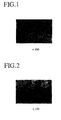
- Figs. 1 and 2 are photomicrographs (x 100) showing the typical microstructures of the targets of the present invention (Examples 2 and 5).
- An average diameter of Fe, Co and Fe-Nb particles and thickness of a diffusion-bonding phase in the microstructure of the target were calculated from the photomicrographs of Figs. 1 and 2 by an image analysis method. As a result, it was found that particles dispersed in the target were almost in the same size as that of the starting powder because of a low sintering temperature as shown in Table 2.
- the thickness of the diffusion-bonding phase could be restricted to 30 ⁇ m or less.
- Example Average Diameter of Dispersed Particles ⁇ m
- Thickness of Bonding Phase ⁇ m
- Oxygen Content ppm
- Fe Co Fe-Nb Average 1 190 200 190 193 15 415 2 120 130 120 123 18 470 3 95 95 90 93 21 510 4 65 65 60 63 23 760 5 30 35 35 33 26 830 Comparative Example 1 330 300 290 307 12 380
- Each sintered body before worked to a target was machined to obtain a columnar sample of 30 mm x 10 mm x 5 mm, and a B-H curve was measured at a maximum magnetic field of 796 kA/m (10 kOe) by using a DC magnetic flux meter with respect to each sample. From the B-H curve, a maximum permeability ( ⁇ max ) and a saturation magnetization were determined. The results are shown in Fig. 4.
- Fig. 4 shows the relations of a maximum permeability and a saturation magnetization with an average diameter of the entire particles (Fe particles, Co particles and Fe-Nb particles) dispersed in the sintered body. It is clear from the data shown in Fig. 4 that as the average diameter decreases the maximum permeability and the saturation magnetization decrease, and that particularly when the average diameter is less than 125 ⁇ m, the decrease in the maximum permeability and the saturation magnetization is remarkable, meaning that the sintered body can be used as a target suitable for a magnetron-type sputtering apparatus.
- Tb-Fe alloy powder (Tb: 58.4 atomic %, Fe: balance), pure Fe powder, pure Co powder, Fe-Cr alloy powder (Cr: 15.9 atomic %, Fe: balance), and Fe-Nb alloy powder (Nb: 12 atomic %, Fe: balance) were produced.
- sieves of 42 mesh, 60 mesh, 100 mesh, 140 mesh, 200 mesh and 330 mesh according to the New JIS Standards each of the Tb-Fe alloy powder, the pure Fe powder, the pure Co powder, the Fe-Cr alloy powder, and the Fe-Nb alloy powder was classified to provide six classes of powder having different particle sizes as shown in Table 3.
- 1,846 g of the Tb-Fe alloy powder, 95 g of the pure Fe powder, 243 g of the pure Co powder, 706 g of the Fe-Cr alloy powder, and 1,031 g of the Fe-Nb alloy powder were taken from the same class of powder size, and mixed together in a V-type blender to provide six types of mixed powder (composition: Tb 18 -Fe 66 -Co 8 -Cr 4 -Nb 4 , atomic %) having different particle sizes. No.
- Each of six types of mixed powder was charged into a capsule made of soft steel, and subjected to a HIP treatment under the same conditions as in Example 1 except for a HIP temperature of 670°C.
- Each sintered body obtained by the HIP treatment was worked with a lathe to a target of 254 mm in diameter and 6 mm in thickness. The average diameter of particles dispersed in the target, the thickness of bonding phase and the oxygen content were measured in the same manner as in Example 1. The results are shown in Table 4.
- Example Average Diameter of Dispersed Particles ( ⁇ m) Thickness of Bonding Phase ( ⁇ m) Oxygen Content (ppm) Fe Co Fe-Cr Fe-Nb Average 6 200 200 200 190 198 19 460 7 120 135 120 120 124 21 512 8 90 95 90 85 90 23 730 9 65 65 65 60 64 26 800 10 30 35 35 35 34 28 910 Comparative Example 2 320 310 290 290 303 15 315
- Fig. 5 shows the relations of a maximum permeability and a saturation magnetization with an average diameter of the entire particles (Fe particles, Co particles, Fe-Cr particles and Fe-Nb particles) dispersed in the sintered body. It is clear from the data shown in Fig. 5 that as the average diameter decreases the maximum permeability and the saturation magnetization decrease, and that particularly when the average diameter is less than 125 ⁇ m, the decrease in the maximum permeability and the saturation magnetization is remarkable.
- the sintered body in which Fe and Co, and Fe-Cr and Fe-Nb alloys which are alloys of an iron-group metal and a corrosion resistance-improving metal are dispersed in the form of fine particles according to the present invention, can be used as a target suitable for a magnetron-type sputtering apparatus.
- Tb-Fe alloy powder (Tb: 58.4 atomic %, Fe: balance), pure Fe powder, pure Co powder, and Fe-X alloy powder (kinds and amounts of X: shown in Table 5) were produced. With sieves of 140 mesh and 200 mesh according to the New JIS Standards, each of the Tb-Fe alloy powder, the pure Fe powder, the pure Co powder, the Fe-X alloy powder was classified to provide an average diameter of about 125 ⁇ m.
- the Tb-Fe alloy powder, the pure Fe powder, the pure Co powder and the Fe-X alloy powder in amounts shown in Table 5 were mixed together to provide a mixed powder (composition: Tb 24 -Fe 62 -Co 12 -X 2 , atomic %), wherein X is Al, Ti, Ta, Pt, Pd or Cu.
- a mixed powder composition: Tb 24 -Fe 62 -Co 12 -X 2 , atomic %), wherein X is Al, Ti, Ta, Pt, Pd or Cu.
- an average diameter D 50 was measured by a sedimentation-type particle size measurement apparatus on a small amount of a sample taken from each mixed powder.
- the average diameter D 50 is also shown in Table 5.
- the resultant mixed powder was subjected to a HIP treatment under the same conditions as in Example 1.
- the resultant sintered body was polished to measure its microstructure by an optical microscope.
- the average diameter of particles (Fe, Co and Fe-X alloy) dispersed in the Tb-Fe eutectic structure, a matrix phase of the sintered body, was determined by an image analysis method.
- the maximum permeability of each sintered body is also shown in Table 5.
- Table 5 shows that the targets of the present invention have as low a maximum permeability as about 10-12, and that the maximum permeability can be effectively reduced by making the iron-group metal powder and the alloy powder of the iron-group metal and the corrosion resistance-improving metals finer.
- Tb-Fe alloy powder (Tb: 58.4 atomic %, Fe: balance), pure Fe powder, pure Co powder, and Fe-Nb alloy powder (Nb: 12 atomic %, Fe: balance) were produced.
- Pure Nb powder was produced by a plasma electrode rotation method. With sieves of 140 mesh and 200 mesh according to the New JIS Standards, each of the Tb-Fe alloy powder, the pure Fe powder, the pure Co powder, the pure Nb powder and the Fe-Nb alloy powder was classified to provide an average diameter of about 100 ⁇ m as shown in Table 6.
- these powders were mixed by two methods (A) and (B) to provide a target composition of Tb 25 -Fe 62 -Co 11 -Nb 2 (atomic %). Namely, Nb was added in the form of alloy powder of Fe-12Nb (atomic %) in the method (A), while Nb was added in the form of pure Nb powder in the method (B).
- An average diameter D 50 was measured by a sedimentation-type particle size measurement apparatus on a small amount of a sample taken from each mixed powder (A), (B).
- the average diameter D 50 was 106 ⁇ m for (A) and 102 ⁇ m for (B).
- Example 7 Each of the mixed powders (A) and (B) was pressure-sintered and machined into a target of 101 mm in diameter and 3 mm in thickness in the same manner as in Example 1.
- No. Average Diameter D 50 ( ⁇ m) Fe Co Nb Fe-Nb Tb-Fe Mixture Ex. 17 102 110 - 108 104 106 Co.
- Ex. 3 102 100 104 - 102 102
- Each of the resultant targets was mounted in a magnetron-type sputtering apparatus to investigate the in-plane distributions of Tb and Nb in thin-film layers formed on a substrate of #7059 glass (101 mm diameter, and 1 mm thickness) available from Corning at a cumulative sputtering time of 12 kW ⁇ hr under the film-forming conditions of: Base pressure: 1.0 x 10 -4 Pa or less, Argon pressure: 1.1 Pa, Input power: 400 W, Distance between target and substrate: 70 mm, and Target and substrate: Stationary.
- the concentrations of Tb and Nb in the thin-film layers were measured by an X-ray microanalyzer.
- the in-plane distributions of Tb and Nb were evaluated from the relations of the concentrations of Tb and Nb and a distance from a center of the substrate. The results are shown in Fig. 6. It is clear from Fig. 6 that the target (A) of Example 17 containing Fe-Nb alloy particles has a uniform in-plane distribution of Tb, and that the target (A) has a more uniform in-plane distribution of Nb than the target (B) of Comparative Example 3.
- Fig. 7(a) shows the relation between a cumulative sputtering time (kW ⁇ hr) and a coercivity (kA/m) of thin-film layers
- Fig. 7(b) shows the relation between a cumulative sputtering time and the concentration of Nb (atomic %).
- the target (B) produced by adding pure Nb powder (Comparative Example 3)
- the variation of the concentration of Nb is as large as ⁇ 0.8 atomic %
- the variation of the coercivity is also large.
- the target (A) produced by adding Fe-Nb alloy powder Example 17
- the variation of the concentration of Nb is as small as ⁇ 0.2 atomic %, and the level of the coercivity is stable.
- the rare earth metal-iron-group metal target of the present invention for magneto-optical recording media has low maximum permeability and saturation magnetization, it can sufficiently utilize the advantages of a magnetron-type sputtering apparatus in which magnetic flux leaks from a surface of the target, thereby increasing the use efficiency of the target.
- the target of the present invention has a microstructure containing a eutectic structure (matrix phase) and an iron-group metal phase bonded to each other, the resultant thin-film layers have uniform distributions of rare earth metals. Also, since the corrosion resistance-improving metals exist in the form of alloys with at least one iron-group metal, the corrosion resistance-improving metals are also distributed in the thin-film layers uniformly.
- the target of the present invention can produce thin-film layers having uniform microstructures required for magneto-optical recording media, meaning that it is highly suitable for magneto-optical recording media-producing means.
Landscapes
- Engineering & Computer Science (AREA)
- Chemical & Material Sciences (AREA)
- Power Engineering (AREA)
- Manufacturing & Machinery (AREA)
- Chemical Kinetics & Catalysis (AREA)
- Materials Engineering (AREA)
- Mechanical Engineering (AREA)
- Metallurgy (AREA)
- Organic Chemistry (AREA)
- Physical Vapour Deposition (AREA)
- Thin Magnetic Films (AREA)
- Powder Metallurgy (AREA)
Claims (7)
- Target für magnetooptische Aufzeichnungsmedien, das aus einem gesinterten Körper mit einem Mikrogefüge besteht, das als Matrixphase ein eutektisches Gefüge aus wenigstens einem Seltenerdmetall und wenigstens einem Eisengruppenmetall aufweist, wobei die Matrixphase erste Teilchen (I) aus einem reinen Eisengruppenmetall oder einer Legierung desselben und zweite Teilchen (II) aus wenigstens einem Metall enthält, das aus der aus Ti, Al, Cu, Cr, Nb, Ta, Pd und Pt und wenigstens einem Eisengruppenmetall bestehenden Gruppe gewählt ist,
dadurch gekennzeichnet,
daß die ersten Teilchen (I) und die zweiten Teilchen (II) gleichmäßig in der Matrixphase dispergiert sind und daß der Durchschnittsdurchmesser der Teilchen (I) und der Durchschnittsdurchmesser der Teilchen (II) beide 200 µm oder weniger sind. - Target nach Anspruch 1, wobei der Durchschnittsdurchmesser der ersten Teilchen (I) und der Durchschnittsdurchmesser der zweiten Teilchen (II) beide 125 µm oder weniger sind.
- Target nach Anspruch 1, wobei das Target eine Sättigungsmagnetisierung (4πIs) von 1 T (10.000 G) oder weniger hat.
- Target nach Anspruch 1, wobei der Unterschied zwischen dem Durchschnittsdurchmesser der Mischung der ersten Teilchen (I) und der zweiten Teilchen (II) und dem Durchschnittsdurchmesser sowohl der Teilchen (I) als auch der Teilchen (II) innerhalb von 20% des Durchschnittsdurchmessers der Mischung der ersten Teilchen (I) und der zweiten Teilchen (II) ist.
- Target nach Anspruch 1, wobei eine Bindephase mit einer Dicke von 30 µm oder darunter zwischen dem eutektischen Gefüge und den ersten und zweiten Teilchen vorhanden ist.
- Verfahren zur Herstellung eines Targets für magnetooptische Aufzeichnungsmedien, das die Schritte:dadurch gekennzeichnet,(a) rasches Abschrecken einer Schmelze von wenigstens einem Seltenerdmetall und wenigstens einem Eisengruppenmetall zur Bildung eines ersten Pulvers mit einem eutektischen Gefüge;(b) Vermischen des ersten Pulvers mit zweitem Pulver (I) aus einem reinen Eisengruppenmetall oder einer Legierung desselben und mit drittem Pulver (II) aus wenigstens einem Metall, das aus der aus Ti, Al, Cu, Cr, Nb, Ta, Pd und Pt und wenigstens einem Eisengruppenmetall bestehenden Gruppe gewählt wird; und(c) Drucksintern des erhaltenen gemischten Pulvers bei einer niedrigeren Temperatur als einer Flüssigphasenauftrittstemperatur aufweist,
daß der Durchschnittsdurchmesser der Teilchen des zweiten Pulvers (I) und der Durchschnittsdurchmesser der Teilchen des dritten Pulvers (II) beide 200 µm oder weniger sind. - Verfahren nach Anspruch 6, bei dem der Unterschied zwischen dem Durchschnittsdurchmesser der Teilchen einer Mischung des ersten Pulvers, des zweiten Pulvers (I) und des dritten Pulvers (II) und dem Durchschnittsdurchmesser der Teilchen von sowohl dem ersten Pulver als auch dem zweiten Pulver (I) als auch dem dritten Pulver (II) innerhalb von 20 % des Durchschnittsdurchmessers der Teilchen der Mischung des ersten Pulvers, des zweiten Pulvers (I) und des dritten Pulvers (II) ist.
Applications Claiming Priority (2)
| Application Number | Priority Date | Filing Date | Title |
|---|---|---|---|
| JP4355007A JPH06184740A (ja) | 1992-12-17 | 1992-12-17 | 光磁気記録媒体用ターゲットおよびその製造方法 |
| JP355007/92 | 1992-12-17 |
Publications (2)
| Publication Number | Publication Date |
|---|---|
| EP0603750A1 EP0603750A1 (de) | 1994-06-29 |
| EP0603750B1 true EP0603750B1 (de) | 1999-03-17 |
Family
ID=18441346
Family Applications (1)
| Application Number | Title | Priority Date | Filing Date |
|---|---|---|---|
| EP93120332A Expired - Lifetime EP0603750B1 (de) | 1992-12-17 | 1993-12-16 | Target für magnetooptische Aufzeichnungsmedien und Verfahren zu seiner Herstellung |
Country Status (5)
| Country | Link |
|---|---|
| US (1) | US5447801A (de) |
| EP (1) | EP0603750B1 (de) |
| JP (1) | JPH06184740A (de) |
| KR (1) | KR0129795B1 (de) |
| DE (1) | DE69323971T2 (de) |
Families Citing this family (16)
| Publication number | Priority date | Publication date | Assignee | Title |
|---|---|---|---|---|
| KR0141194B1 (ko) * | 1994-06-10 | 1998-07-15 | 김광호 | 스퍼터링용 타아게트의 제조방법 |
| JP3098204B2 (ja) * | 1997-03-07 | 2000-10-16 | ティーディーケイ株式会社 | 光磁気記録用合金ターゲット、その製造方法およびその再生方法 |
| US6055140A (en) | 1997-07-25 | 2000-04-25 | Seagate Technology, Inc. | Rigid disc plastic substrate with high stiffness insert |
| JP4491844B2 (ja) * | 1998-07-24 | 2010-06-30 | 東ソー株式会社 | スパッタリングターゲット |
| US7153468B2 (en) * | 2000-08-18 | 2006-12-26 | Honeywell International Inc. | Physical vapor deposition targets and methods of formation |
| US6682636B2 (en) * | 2000-08-18 | 2004-01-27 | Honeywell International Inc. | Physical vapor deposition targets and methods of formation |
| WO2003098976A1 (en) * | 2002-05-22 | 2003-11-27 | Fuji Electric Holdings Co.,Ltd. | Organic el luminescence device |
| US20070099332A1 (en) * | 2005-07-07 | 2007-05-03 | Honeywell International Inc. | Chalcogenide PVD components and methods of formation |
| US20070007505A1 (en) * | 2005-07-07 | 2007-01-11 | Honeywell International Inc. | Chalcogenide PVD components |
| US7488526B2 (en) | 2005-11-22 | 2009-02-10 | Ricoh Company, Ltd. | Sputtering target and manufacturing method therefor, and optical recording medium and manufacturing method therefor |
| US20080112878A1 (en) * | 2006-11-09 | 2008-05-15 | Honeywell International Inc. | Alloy casting apparatuses and chalcogenide compound synthesis methods |
| US20080202916A1 (en) * | 2007-02-22 | 2008-08-28 | Heraeus Incorporated | Controlling magnetic leakage flux in sputtering targets containing magnetic and non-magnetic elements |
| JP2009203537A (ja) * | 2008-02-29 | 2009-09-10 | Hitachi Metals Ltd | Co−Fe系合金スパッタリングターゲット材およびその製造方法 |
| JP5418897B2 (ja) * | 2008-08-04 | 2014-02-19 | 日立金属株式会社 | Co−Fe系合金スパッタリングターゲット材の製造方法 |
| JP5403418B2 (ja) * | 2008-09-22 | 2014-01-29 | 日立金属株式会社 | Co−Fe−Ni系合金スパッタリングターゲット材の製造方法 |
| CN107408397B (zh) * | 2015-03-12 | 2019-07-05 | 山阳特殊制钢株式会社 | Ni系溅射靶材和磁记录介质 |
Citations (1)
| Publication number | Priority date | Publication date | Assignee | Title |
|---|---|---|---|---|
| EP0288010A2 (de) * | 1987-04-20 | 1988-10-26 | Hitachi Metals, Ltd. | Targetmaterial aus einem Metall der seltenen Erden und einem Metall der Eisengruppe, Legierungspulver und Verfahren zur Herstellung dieses Materials |
Family Cites Families (7)
| Publication number | Priority date | Publication date | Assignee | Title |
|---|---|---|---|---|
| JP2597380B2 (ja) * | 1988-03-23 | 1997-04-02 | 日立金属株式会社 | 希土類金属−遷移金属ターゲット用合金粉末の製造方法および希土類金属−遷移金属ターゲットの製造方法 |
| JP2894695B2 (ja) * | 1988-03-30 | 1999-05-24 | 日立金属株式会社 | 希土類金属−鉄族金属ターゲットおよびその製造方法 |
| DE3935698C2 (de) * | 1988-10-26 | 1995-06-22 | Sumitomo Metal Mining Co | Legierungstarget für die Herstellung eines magneto-optischen Aufzeichnungsmediums |
| JPH02138463A (ja) * | 1988-11-16 | 1990-05-28 | Hitachi Metals Ltd | スパッタリング用ターゲット材 |
| DE3929690A1 (de) * | 1989-09-07 | 1991-03-14 | Hoechst Ag | Elektrochemisches verfahren zur herstellung von elektrisch leitenden poly(alkoxythiophenen) unter zusatz von carbonsaeuren |
| JPH05271915A (ja) * | 1992-03-24 | 1993-10-19 | Hitachi Metals Ltd | 光磁気記録媒体用ターゲット材およびその製造方法 |
| JPH05320888A (ja) * | 1992-05-20 | 1993-12-07 | Hitachi Metals Ltd | 光磁気記録媒体用ターゲット |
-
1992
- 1992-12-17 JP JP4355007A patent/JPH06184740A/ja active Pending
-
1993
- 1993-12-09 US US08/163,550 patent/US5447801A/en not_active Expired - Fee Related
- 1993-12-16 EP EP93120332A patent/EP0603750B1/de not_active Expired - Lifetime
- 1993-12-16 DE DE69323971T patent/DE69323971T2/de not_active Expired - Fee Related
- 1993-12-17 KR KR1019930028168A patent/KR0129795B1/ko not_active Expired - Fee Related
Patent Citations (1)
| Publication number | Priority date | Publication date | Assignee | Title |
|---|---|---|---|---|
| EP0288010A2 (de) * | 1987-04-20 | 1988-10-26 | Hitachi Metals, Ltd. | Targetmaterial aus einem Metall der seltenen Erden und einem Metall der Eisengruppe, Legierungspulver und Verfahren zur Herstellung dieses Materials |
Also Published As
| Publication number | Publication date |
|---|---|
| DE69323971D1 (de) | 1999-04-22 |
| US5447801A (en) | 1995-09-05 |
| JPH06184740A (ja) | 1994-07-05 |
| KR940016050A (ko) | 1994-07-22 |
| DE69323971T2 (de) | 1999-08-05 |
| EP0603750A1 (de) | 1994-06-29 |
| KR0129795B1 (ko) | 1998-04-07 |
Similar Documents
| Publication | Publication Date | Title |
|---|---|---|
| US5447801A (en) | Target for magneto-optical recording media and method for producing same | |
| US6071323A (en) | Alloy target, its fabrication, and regeneration processes | |
| US5098649A (en) | Rare earth metal-iron group metal target, alloy powder therefor and method of producing same | |
| US6406600B1 (en) | CoPt-base sputtering target, method of making same, magnetic recording film and Co-Pt-base magnetic recording medium | |
| US4814053A (en) | Sputtering target and method of preparing same | |
| US20080083616A1 (en) | Co-Fe-Zr BASED ALLOY SPUTTERING TARGET MATERIAL AND PROCESS FOR PRODUCTION THEREOF | |
| US7381282B2 (en) | Co alloy target and its production method, soft magnetic film for perpendicular magnetic recording and perpendicular magnetic recording medium | |
| JP2005530925A (ja) | 高ptfスパッタリングターゲット及びその製造方法 | |
| JP3662251B2 (ja) | 磁気光学合金製のスパッターターゲット | |
| US4941920A (en) | Sintered target member and method of producing same | |
| EP0640964B1 (de) | Target für ein magnetooptisches Aufzeichnungsmedium und Verfahren zu seiner Herstellung | |
| JP3076141B2 (ja) | 磁性薄膜用ターゲット材とその製造方法、Fe−M−C軟磁性膜とその製造方法、およびこれを用いた磁気ヘッドならびに磁気記録再生装置 | |
| JPH02107762A (ja) | 光磁気記録用合金ターゲット | |
| JPS6270550A (ja) | タ−ゲツト材 | |
| JPH07252649A (ja) | 光磁気記録媒体用ターゲット | |
| JPH0119448B2 (de) | ||
| US5710384A (en) | Magneto-optical recording medium target and manufacture method of same | |
| JP2002212716A (ja) | 高スパッタ電力ですぐれた耐割損性を発揮する光磁気記録媒体の記録層形成用焼結スパッタリングターゲット材 | |
| JP2894695B2 (ja) | 希土類金属−鉄族金属ターゲットおよびその製造方法 | |
| JP2000038661A (ja) | Co合金系ターゲット、その製造方法、スパッタリング装置、磁気記録膜および磁気記録装置 | |
| Marukhin et al. | Application of laser processing for powder materials of alloys of the Fe-Nd-B system to create a micromagnetic system | |
| JPH05271915A (ja) | 光磁気記録媒体用ターゲット材およびその製造方法 | |
| JP2000038660A (ja) | CoPt系スパッタリングターゲットおよびその製造方法ならびにCoPt系磁気記録媒体 | |
| JPH01242733A (ja) | 希土類金属−遷移金属ターゲット用合金粉末の製造方法および希土類金属−遷移金属ターゲットの製造方法 | |
| JPH0766585B2 (ja) | 光磁気記録媒体形成用Tb―Fe系焼結スパッタリングターゲット材 |
Legal Events
| Date | Code | Title | Description |
|---|---|---|---|
| PUAI | Public reference made under article 153(3) epc to a published international application that has entered the european phase |
Free format text: ORIGINAL CODE: 0009012 |
|
| AK | Designated contracting states |
Kind code of ref document: A1 Designated state(s): DE GB NL |
|
| 17P | Request for examination filed |
Effective date: 19940818 |
|
| 17Q | First examination report despatched |
Effective date: 19970516 |
|
| GRAG | Despatch of communication of intention to grant |
Free format text: ORIGINAL CODE: EPIDOS AGRA |
|
| GRAG | Despatch of communication of intention to grant |
Free format text: ORIGINAL CODE: EPIDOS AGRA |
|
| GRAH | Despatch of communication of intention to grant a patent |
Free format text: ORIGINAL CODE: EPIDOS IGRA |
|
| GRAH | Despatch of communication of intention to grant a patent |
Free format text: ORIGINAL CODE: EPIDOS IGRA |
|
| GRAA | (expected) grant |
Free format text: ORIGINAL CODE: 0009210 |
|
| AK | Designated contracting states |
Kind code of ref document: B1 Designated state(s): DE GB NL |
|
| REF | Corresponds to: |
Ref document number: 69323971 Country of ref document: DE Date of ref document: 19990422 |
|
| PLBE | No opposition filed within time limit |
Free format text: ORIGINAL CODE: 0009261 |
|
| STAA | Information on the status of an ep patent application or granted ep patent |
Free format text: STATUS: NO OPPOSITION FILED WITHIN TIME LIMIT |
|
| 26N | No opposition filed | ||
| PGFP | Annual fee paid to national office [announced via postgrant information from national office to epo] |
Ref country code: DE Payment date: 20001211 Year of fee payment: 8 |
|
| PGFP | Annual fee paid to national office [announced via postgrant information from national office to epo] |
Ref country code: GB Payment date: 20001213 Year of fee payment: 8 |
|
| PGFP | Annual fee paid to national office [announced via postgrant information from national office to epo] |
Ref country code: NL Payment date: 20001231 Year of fee payment: 8 |
|
| PG25 | Lapsed in a contracting state [announced via postgrant information from national office to epo] |
Ref country code: GB Free format text: LAPSE BECAUSE OF NON-PAYMENT OF DUE FEES Effective date: 20011216 |
|
| REG | Reference to a national code |
Ref country code: GB Ref legal event code: IF02 |
|
| PG25 | Lapsed in a contracting state [announced via postgrant information from national office to epo] |
Ref country code: NL Free format text: LAPSE BECAUSE OF NON-PAYMENT OF DUE FEES Effective date: 20020701 |
|
| PG25 | Lapsed in a contracting state [announced via postgrant information from national office to epo] |
Ref country code: DE Free format text: LAPSE BECAUSE OF NON-PAYMENT OF DUE FEES Effective date: 20020702 |
|
| GBPC | Gb: european patent ceased through non-payment of renewal fee |
Effective date: 20011216 |
|
| NLV4 | Nl: lapsed or anulled due to non-payment of the annual fee |
Effective date: 20020701 |