EP0603861B1 - Multiplex-Hologramm für eine zentrisch montierte, hochgesetzte Bremsleuchte mit Fernbeleuchtung - Google Patents
Multiplex-Hologramm für eine zentrisch montierte, hochgesetzte Bremsleuchte mit Fernbeleuchtung Download PDFInfo
- Publication number
- EP0603861B1 EP0603861B1 EP93120718A EP93120718A EP0603861B1 EP 0603861 B1 EP0603861 B1 EP 0603861B1 EP 93120718 A EP93120718 A EP 93120718A EP 93120718 A EP93120718 A EP 93120718A EP 0603861 B1 EP0603861 B1 EP 0603861B1
- Authority
- EP
- European Patent Office
- Prior art keywords
- hologram
- angular
- blocks
- block
- single grating
- Prior art date
- Legal status (The legal status is an assumption and is not a legal conclusion. Google has not performed a legal analysis and makes no representation as to the accuracy of the status listed.)
- Expired - Lifetime
Links
- 239000007787 solid Substances 0.000 claims description 41
- 238000005286 illumination Methods 0.000 claims description 23
- 230000002093 peripheral effect Effects 0.000 claims description 22
- 238000000034 method Methods 0.000 claims description 9
- 239000000463 material Substances 0.000 claims 2
- 238000010276 construction Methods 0.000 description 5
- 239000000758 substrate Substances 0.000 description 4
- 239000012530 fluid Substances 0.000 description 3
- 239000011521 glass Substances 0.000 description 3
- 238000003491 array Methods 0.000 description 2
- 230000005540 biological transmission Effects 0.000 description 2
- 238000009434 installation Methods 0.000 description 2
- 230000001419 dependent effect Effects 0.000 description 1
- 230000000994 depressogenic effect Effects 0.000 description 1
- 230000000694 effects Effects 0.000 description 1
- 238000007687 exposure technique Methods 0.000 description 1
- 229910052736 halogen Inorganic materials 0.000 description 1
- 150000002367 halogens Chemical class 0.000 description 1
- 238000012986 modification Methods 0.000 description 1
- 230000004048 modification Effects 0.000 description 1
- 239000003973 paint Substances 0.000 description 1
- 239000010453 quartz Substances 0.000 description 1
- 230000035945 sensitivity Effects 0.000 description 1
- VYPSYNLAJGMNEJ-UHFFFAOYSA-N silicon dioxide Inorganic materials O=[Si]=O VYPSYNLAJGMNEJ-UHFFFAOYSA-N 0.000 description 1
Images



Classifications
-
- G—PHYSICS
- G02—OPTICS
- G02B—OPTICAL ELEMENTS, SYSTEMS OR APPARATUS
- G02B5/00—Optical elements other than lenses
- G02B5/32—Holograms used as optical elements
-
- B—PERFORMING OPERATIONS; TRANSPORTING
- B60—VEHICLES IN GENERAL
- B60Q—ARRANGEMENT OF SIGNALLING OR LIGHTING DEVICES, THE MOUNTING OR SUPPORTING THEREOF OR CIRCUITS THEREFOR, FOR VEHICLES IN GENERAL
- B60Q1/00—Arrangement of optical signalling or lighting devices, the mounting or supporting thereof or circuits therefor
- B60Q1/26—Arrangement of optical signalling or lighting devices, the mounting or supporting thereof or circuits therefor the devices being primarily intended to indicate the vehicle, or parts thereof, or to give signals, to other traffic
- B60Q1/44—Arrangement of optical signalling or lighting devices, the mounting or supporting thereof or circuits therefor the devices being primarily intended to indicate the vehicle, or parts thereof, or to give signals, to other traffic for indicating braking action or preparation for braking, e.g. by detection of the foot approaching the brake pedal
-
- G—PHYSICS
- G03—PHOTOGRAPHY; CINEMATOGRAPHY; ANALOGOUS TECHNIQUES USING WAVES OTHER THAN OPTICAL WAVES; ELECTROGRAPHY; HOLOGRAPHY
- G03H—HOLOGRAPHIC PROCESSES OR APPARATUS
- G03H1/00—Holographic processes or apparatus using light, infrared or ultraviolet waves for obtaining holograms or for obtaining an image from them; Details peculiar thereto
- G03H1/22—Processes or apparatus for obtaining an optical image from holograms
- G03H1/2202—Reconstruction geometries or arrangements
Definitions
- the disclosed invention is directed generally to holograms for center high mounted stoplights for vehicles, and more particularly to a hologram that efficiently meets the required brightness and angular coverage and to an exposure technique for recording such hologram.
- CCMSLs center high mounted stoplights
- the high mounted stoplights are intended to maximize the visibility of the automobile braking indicators to drivers following the braking vehicle, and are commonly mounted on the rear window of an automobile.
- High mounted stoplights have commonly been implemented as a standard lenticular lens, a red filter, an illuminating incandescent bulb, and a reflector enclosed in a housing that is typically secured adjacent the top or bottom of an automobile rear window.
- the bulky housing partially obscures the rearward vision of the driver, and moreover imposes limitations on the design of the automobile.
- center high mounted stoplights have been also integrated into automobile body parts such as rear decks, spoilers, roofs, which to some degree substantially reduce or remove the rearward vision problem.
- stoplights are complex and may impose limitations on the design of the automobile.
- Holographic center high mounted stoplights have also been developed in order to efficiently meet the stoplight regulations.
- a consideration with holograms for holographic center high mounted stoplights are the luminous intensity and angular coverage requirements. Such requirements generally include a quantitative aspect that defines luminous intensity over a defined solid angular range, and a qualitative aspect that requires visibility over a horizontal angular range that is greater than the horizontal component of the defined solid angular range.
- the regulations require a brighter region generally in the center of the angular region of coverage.
- a straightforward procedure for recording a hologram for a center high mounted stoplight would be to record the image of a lenticular lens array that spreads light uniformly over a selected angular coverage (e.g., two lenticular arrays rotated 90 degrees with respect to each other and laminated together).
- a consideration with this procedure includes the generation of spurious holograms since the lenses of the array would cover overlapping areas. Such spurious holograms reduce the efficiency of the desired stoplight hologram and moreover limit the see through clarity of the hologram. Also, precise control of the direction of the diffracted light is difficult.
- GB-A-2 240 390 discloses a holographic center high mounted stoplight system for a vehicle according to the preamble of claim 1 which utilizes a transmission hologram mounted inside the rear window which comprises a plurality of divisions having different diffraction characteristics from each other. Almost all incident light rays from a light source illuminating the hologram are diffracted in a given direction rearwards of the vehicle.
- a holographic center high mounted stoplight shall be provided wherein the direction of diffraction can be precisely controlled.
- a holographic center high mounted stoplight system that includes a hologram layer having a plurality of single grating holograms formed in therein, each single grating hologram configured to diffract light at a respective predetermined angle; and a playback source that provides playback illumination having angular spread such that each single grating hologram diffracts light over a solid angular region.
- FIG. 1 sets forth a schematic sectional view illustrating a vehicle center high mounted stop light installation employing a hologram constructed in accordance with the invention.
- FIG. 2 sets forth a luminous intensity distribution graph depicting present vertical and horizontal requirements in candelas for center high mounted stoplights.
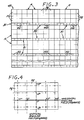
- FIG. 3 schematically illustrates a planar CHMSL hologram having a plurality of primary hologram blocks and a plurality of secondary hologram blocks in accordance with the invention.
- FIG. 4 schematically illustrates the respective solid angular regions of diffraction of the single grating hologram cells of each of the primary hologram blocks of the hologram of FIG. 3.
- FIG. 5 schematically illustrates the respective solid angular regions of diffraction of the single grating hologram cells of each of the secondary hologram blocks of the hologram of FIG. 3.
- FIG. 6 schematically illustrates a mask that is utilized for constructing the single grating hologram cells of the first hologram blocks of the CHMSL hologram of FIG. 3.
- FIG. 7 schematically illustrates a mask that is utilized for constructing the single grating hologram cells of the second hologram blocks of the CHMSL hologram of FIG. 3.
- FIG. 8 sets forth by way of illustrative example an exposure system for constructing the single grating hologram cells of the CHMSL hologram of FIG. 3.
- a center high mounted stoplight system which includes a hologram assembly 20 and an illumination source 30.
- the hologram assembly 20 which includes a volume transmission hologram described further herein, is secured to the inside surface of an automobile rear window 211, and is substantially transparent to the rearward vision of the driver.
- the illumination source 30 is mounted forward of the hologram assembly 20 and out of the rearward viewing angle of the driver, for example, adjacent the inside of the roof of the automobile, and illuminates the volume hologram of the hologram assembly 20 with a diverging beam.
- the volume hologram of the hologram assembly is constructed to provide, when illuminated by the illumination source 30, an appropriate image that is visible from behind the automobile over the appropriate vertical and horizontal viewing angles.
- the illumination source 30 includes an incandescent lamp 15, such as a quartz halogen bulb, a parabolic reflector 17 that generally confines the illumination to the hologram assembly 20, and a high pass filter 19 having a cutoff wavelength of about 600 nanometers (nm).
- an incandescent lamp 15 is connected to the brake light actuating circuit of the automobile so as to be energized when the brake pedal is depressed.
- FIG. 2 set forth therein is a graph showing the luminous intensity (in candelas) versus angular field requirements for a CHMSL for the field defined as (a) 10 degrees up and 5 degrees down relative to a central horizontal plane that passes through the center of the CHMSL, and (b) 10 degrees left and right relative to a central vertical plane that passes through the center of the CHMSL and contains the longitudinal axis of the vehicle, as set forth in US Federal Motor Vehicle Safety Standards No. 108.
- the numbers in the graph identify the minimum luminous intensities at those angular locations in candelas, and the entire angular field is subject to a 160 candela maximum at any given angular position.
- FIG. 3 schematically illustrated therein is a view of a planar CHMSL hologram 49 in accordance with the invention prior to installation in the hologram assembly, with the surface shown being the surface that will face the outside of the vehicle when installed.
- the CHMSL hologram 49 comprises rows of identically sized primary hologram blocks A alternatingly and non-overlappingly interleaved with rows of identically sized secondary hologram blocks B1 and B2 (collectively hologram blocks B).
- Each row of hologram blocks A includes non-overlapping primary hologram blocks A
- each row of hologram blocks B includes secondary hologram blocks B1 alternatingly interleaved with secondary bologram blocks B2 arranged side-by-side in a non-overlapping manner.
- the first row of hologram blocks A is the top of the CHMSL hologram 49 as it is positioned in the installed hologram assembly of the CHMSL system, whereby each row of holograms blocks is generally aligned with the horizontal.
- the parallel edges of a block that are generally aligned with the horizontal when installed in the vehicle shall be called the top and bottom edges wherein the top edge is closest to the top of the figure and is closest to the top of the rear window when installed.
- the parallel edges of a hologram block that are perpendicular to the top and bottom edges shall be referred to as the side edges.
- the width of a hologram block is measured along the top or bottom edge, while the height of a hologram block is measured along either of the side edges.
- each of the hologram blocks A and the hologram blocks B have the same width, but the hologram blocks B are much shorter in height.
- the primary hologram blocks A are configured to diffract stoplight illumination to meet the Federal requirements of luminous intensity within the required central region of 10° left to 10° right in the horizontal and 5° down to 10° up in the vertical such that diffracted stoplight illumination is visible at all angular positions with such required central region, while the secondary hologram blocks B are configured to diffract stoplight illumination to meet the requirement of peripheral horizontal coverage beyond the central region to 45° left and 45° right of center such that diffracted stoplight illumination is visible at all angular positions within the required peripheral horizontal regions.
- the hologram blocks A cover a larger area than the hologram blocks B, and the ratio of total areas is determined on the basis of the desired distribution of light between the hologram blocks A and the hologram blocks B which can be determined, for example, as follows.
- the luminous intensity required for the secondary hologram blocks B is about 1/10 of the luminous required for the primary hologram blocks A.
- the solid angular coverage of the primary hologram blocks A is about 25 degrees by 25 degrees while the solid angular coverage of the secondary hologram blocks B is a total of about 80 degrees by 6 degrees.
- the area of the primary hologram blocks should be about 13 times as large as the area of the secondary cells.
- each hologram block A should be about 13 times as big as each hologram block B, and since hologram blocks A and the hologram blocks B have the same width, the height of the hologram blocks B should be about 1/13 the height of the hologram blocks A.
- the hologram of FIG. 3 comprises three arrays that are interleaved: an array of primary hologram blocks A, an array of secondary hologram blocks B1, and an array of hologram blocks B2.
- All hologram blocks A are of the same size, and are arranged in a rectilinear pattern wherein the hologram blocks A in each row are contiguous and the rows are separated by identical spacing.
- All hologram blocks B are of the size, and thus the hologram blocks B1 are arranged in a rectilinear pattern wherein the hologram blocks B1 in each row are spaced by identical spacing, and the rows are separated by identical spacing.
- the hologram blocks B2 are arranged in a rectilinear pattern wherein the hologram blocks B2 in each row are spaced by identical spacing, and the rows are separated by identical spacing. More particularly, the spacing between hologram blocks B1 is the same as the spacing between the hologram blocks B2.
- each hologram block A comprises a 2-dimensional array of non-overlapping single grating hologram cells PG, as schematically illustrated in FIG. 3.
- Each single grating hologram cell PG is configured to diffract light within a predetermined angular region PG' within the required central region as shown in FIG. 4.
- each single grating hologram cell PG is recorded to diffract light at only one particular angle, but actually diffracts light over an entire solid angular region PG' as a result of the angular spread of the playback illumination source which is not a perfect point source.
- Each single grating hologram cell PG within each hologram block A diffracts light into a different solid angular region PG', such that the aggregate of diffracted light from all single grating hologram cells PG within each hologram block A entirely fills the required central angular region, as shown in FIG. 4.
- the hologram cells of each hologram block A and the angular spread of the playback source cooperate to diffract light into an array of different angular regions which together provide diffracted stoplight illumination at all angular positions within the required central region.
- the number of hologram cells required for each hologram block A as well as the diffraction angles of the different cells will depend on the angular spread of the particular playback source with which the CHMSL is to be utilized.
- the angular coordinate system included in FIG. 4 includes solid dots at the angular positions as to which the output of the CHMSL hologram must meet a specific luminous intensity requirement.
- the single grating hologram cells PG may be arranged within each hologram block A in a pattern which is analogous to the pattern of diffracted solid angular regions PG' in angular space, as shown in FIGS. 3 and 4.
- the single grating cells PG can be arranged in other patterns while maintaining the same pattern of diffracted solid angular regions PG' in angular space.
- each hologram block B1 is configured to diffract stoplight illumination into the horizontal peripheral angular field that is to the left of the central region, while each hologram block B2 is configured to diffract stoplight illumination into the horizontal peripheral angular field that is to the right of the central region.
- Each of the blocks B1 comprises a 1-dimensional horizontal array of single grating hologram cells SG1, as schematically illustrated in FIG. 3.
- Each single grating hologram cell SG1 is configured to diffract light within a predetermined solid angular region SG1' within the required left horizontal peripheral angular region, as shown in FIG. 5.
- each single grating hologram cell SG1 is recorded to diffract light at only one particular angle, but actually diffracts light over a solid angular region SG1' as a result of the angular spread of the playback illumination source which is not a perfect point source.
- Each single grating hologram cell SG1 within each hologram block B1 diffracts light in a different solid angular region SG1', such that the aggregate of diffracted light from all single grating hologram cells SG1 within each hologram block B1 entirely fills the required left horizontal peripheral angular region, as shown in FIG. 5.
- the hologram cells SG1 of each hologram block B1 and the angular spread of the playback source cooperate to diffract light into an an array of different angular regions which together provide diffracted stoplight illumination at all angular positions within the required left horizontal peripheral angular region.
- the number of hologram cells required for each hologram block B1 as well as the diffraction angles of the different cells will depend on the angular spread of the particular playback source with which the CHMSL is to be utilized.
- FIG. 1 By way of illustrative example, as shown in FIG.
- the single grating hologram cells SG1 cover an angular region that is between (a) about 10 degrees left of the central vertical plane and (b) about 50 degrees left of the central vertical plane, and between (a) about 3 degrees up from the central horizontal plane and (b) about 3 degrees down from the central horizontal plane.
- the single grating hologram cells SG1 may be arranged within each hologram block B1 in a pattern that is analogous to the pattern of diffracted solid angular regions SG1' in angular space, as shown in FIGS. 3 and 5.
- the single grating cells SG1 can be arranged in other patterns while maintaining the same pattern of diffracted solid angular regions SG1' in angular space.
- each secondary block B2 comprises a 1-dimensional horizontal array of single grating hologram cells SG2, as illustrated in FIG. 3.
- Each single grating hologram cell SG2 is configured to diffract light within a predetermined solid angular region SG2' within the required right horizontal peripheral angular region, as shown in FIG. 5.
- each single grating hologram cell SG2 is recorded to diffract light at only one particular angle, but actually diffracts light over a solid angular region SG2' as a result of the angular spread of the playback illumination source which is not a perfect point source.
- Each single grating hologram cell SG2 within each hologram block B2 diffracts light in a different solid angular region SG2', such that the aggregate of diffracted light from all single grating hologram cells SG2 within each hologram block B2 entirely fills the required right horizontal peripheral angular region, as shown in FIG. 5.
- the hologram cells SG2 of each hologram block B2 and the angular spread of the playback source cooperate to diffract light into an array of different angular regions which together provide diffracted stoplight illumination at all angular positions within the required left horizontal peripheral angular region.
- each secondary hologram block B2 is the same size as each secondary hologram block B1, and the number of hologram cells SG2 in each secondary hologram block B2 is the same as the number of hologram cells SG1 in each secondary hologram block B1.
- the diffraction angles of the hologram cells SG2 of each secondary hologram block B2 the mirror images, across the central vertical plane, of the diffraction angles of the hologram cells SG1 of the secondary hologram blocks B1.
- the single grating hologram cells SG2 may be arranged within each hologram block B2 in a pattern that is analogous to the pattern of diffracted solid angular regions SG2' in angular space, as shown in FIGS. 3 and 5.
- the single grating cells SG2 can be arranged in other patterns while maintaining the same pattern of diffracted solid angular regions SG2' in angular space.
- FIG. 8 set forth therein by way of illustrative example is an exposure system for recording a CHMSL hologram in accordance with the invention pursuant to a sequence of exposures to expose the hologram blocks A, a sequence of exposures to expose the hologram blocks B1, and a sequence of exposures to expose the hologram blocks B2.
- a holographic recording assembly 60 which is comprised of a holographic recording 61 layer disposed on a glass substrate 63 and covered by a thin cover layer 65, is disposed beneath an exposure mask assembly 50, which is comprised of a mask 51 having mask openings and a mask supporting substrate 55.
- the hologram recording assembly 60 and the exposure mask assembly 50 are oriented with the exposure mask 51 and the thin cover layer 65 facing each other, and are separated by a very thin layer of index matching fluid 57 which also fills in the mask openings of the mask 51.
- Hologram recording illumination passes through the mask substrate, the mask openings, the index matching fluid, and the thin cover layer to the holographic recording layer.
- the exposure mask assembly 50 is movable, for example by a computer driven micrometer, such that hologram forming cells that correspond to the hologram cells of the CHMSL hologram can be selectively positioned beneath the mask openings for exposure.
- a light absorptive glass layer 71 that absorbs light of the color used for the reference and construction beams is located beneath the substrate 63 of the recording assembly 60 and is optically coupled thereto by a thin layer of index matching fluid 73.
- a light absorbing black paint layer 75 is disposed on the lower side of the glass layer 71.
- the exposure mask 51 in particular comprises a mask 151, schematically illustrated in FIG. 6, having mask openings 151a which leave uncovered each cell of each hologram block A that is in the same cell position, whereby all hologram cells located at the same location in all hologram blocks A are exposed at the same time.
- the number of mask openings 151 is equal to the number of hologram blocks A, that the size of each mask opening 151a corresponds to the hologram cell size, that the horizontal center-to-center spacing between mask openings 151a corresponds to the horizontal center-to-center spacing between the hologram blocks A, and that the vertical center-to-center spacing between mask openings 151a corresponds to the vertical center-to-center spacing between the hologram blocks A.
- the different cells would be exposed by appropriately positioning the mask openings over the cell position intended to be exposed in a particular exposure.
- the exposure mask 51 in particular comprises a mask 251, schematically illustrated in FIG. 7, having mask openings 251a which leave uncovered each cell of each hologram block B1 that is in the same cell position, whereby all hologram cells located at the same location in all hologram blocks B1 are exposed at the same time.
- the number of mask openings 251a is equal to the number of hologram blocks B1, that the size of each mask opening corresponds to the hologram cell size, that the horizontal center-to-center spacing between mask openings 251a corresponds to the horizontal center-to-center spacing between the hologram blocks B1, and that the vertical center-to-center spacing between mask openings 251a corresponds to the vertical center-to-center spacing between the hologram blocks B1.
- the different cells of the hologram blocks B1 would be exposed by appropriately positioning the mask openings 251a over the cell position intended to be exposed in a particular exposure.
- the exposure mask 51 in particular comprises the exposure mask 251, schematically illustrated in FIG. 7, as utilized for exposure of the cells of the hologram blocks B1.
- Such mask leaves uncovered each cell of each hologram block B2 that is in the same cell position, whereby all hologram cells located at the same location in all hologram blocks B2 are exposed at the same time.
- the different cells of the hologram blocks B2 would be exposed by appropriately positioning the mask openings 251a over the cell position intended to be exposed in a particular exposure.
- the reference beam RB comprises a beam that is selected to emulate the shape of the intended playback beam (e.g., collimated, spherically diverging, cylindrically diverging, and so forth), while the object beam OB comprises a collimated beam.
- the incidence angle of the reference beam is selected to correspond to the incidence angle of the intended playback beam, while the incidence angle of the object beam OB is varied for each cell position as required to construct a hologram fringe pattern that will diffract light in the direction designated for that particular cell position.
- each of the cells PG of the primary hologram blocks A can be 2.1 mm (.083 inches) wide and 1.8 mm (.072 inches) high
- each of the cells SG1, SG2 of the secondary hologram blocks B can be 2.1 mm (.083 inches) wide and 0.5 mm (.02 inches) high.
Landscapes
- Physics & Mathematics (AREA)
- General Physics & Mathematics (AREA)
- Optics & Photonics (AREA)
- Engineering & Computer Science (AREA)
- Mechanical Engineering (AREA)
- Diffracting Gratings Or Hologram Optical Elements (AREA)
- Lighting Device Outwards From Vehicle And Optical Signal (AREA)
- Holo Graphy (AREA)
Claims (8)
- Holographisches, mittig hoch aufgenommenes Bremslichtsystem für ein Fahrzeug mit einem rückwärtigen Fenster (211), umfassend:eine holographische Schicht (49) mit einer Mehrzahl von einzelnen darin gebildeten Beugungshologrammen (PG; SG1; SG2), wobei jedes Beugungshologramm (PG; SG1; SG2) zur Beugung von Licht in einem bestimmten vorbestimmten Winkel geeignet ist; undeine Wiedergabequelle (30), die Wiedergabebeleuchtung mit einer derartigen Winkelspreizung abgibt, das jedes einzelne Beugungshologramm (PG; SG1; SG2) Licht über einen festen Winkelbereich beugt (PG'; SG1'; SG2'),dadurch gekennzeichnet, daß die Mehrzahl von einzelnen Beugungshologrammen (PG; SG1; SG2) umfaßt:eine Mehrzahl von primären Hologrammblöcken (A), die jeweils eine Mehrzahl von einzelnen Beugungshologrammen (PG) umfassen, die in einem identischen zweidimensionalen Array angeordnet sind und Licht zu entsprechenden festen Winkelbereichen (PG') innerhalb eines zentralen festen Winkelbereiches brechen, wobei die Anzahl von einzelnen Beugungshologrammen (PG) in jedem ersten Block (A) derart ausgewählt ist, daß das von jedem primären Hologrammblock (A) gebeugte Licht an allen Winkelpositionen innerhalb des zentralen Winkelbereiches sichtbar ist;eine Mehrzahl von ersten sekundären Hologrammblöcken (B1), die jeweils eine Mehrzahl von einzelnen Beugungshologrammen (SG1) aufweisen, die in einem eindimensionalen Array angeordnet sind und Licht zu entsprechenden festen Winkelbereichen (SG1') innerhalb eines ersten peripheren Winkelbereiches beugen, der an den festen zentralen Winkelbereich angrenzt, wobei die Anzahl von einzelnen Beugungshologrammen (SG1) in jedem ersten sekundären Hologrammblock (B1) derart ausgewählt ist, daß das von jedem ersten sekundären Hologrammblock (B1) gebeugte Licht an allen Winkelpositionen innerhalb des ersten peripheren Winkelbereiches sichtbar ist; sowieeine Mehrzahl von zweiten sekundären Hologrammblöcken (B2), die jeweils eine Mehrzahl von einzelnen Beugungshologrammen (SG2) umfassen, die in einem eindimensionalen Array angeordnet sind und Licht zu entsprechenden festen Winkelbereichen (SG2') innerhalb eines zweiten peripheren Winkelbereiches beugen, der an den vorbestimmten zentralen festen Winkelbereich gegenüber dem ersten peripheren Winkelbereich angrenzt und ein Spiegelbild des ersten peripheren Winkelbereiches ist, wobei die Anzahl von Beugungshologrammen (SG2) in jedem zweiten sekundären Hologrammblock (B2) derart ausgewählt ist, daß das von jedem zweiten sekundären Hologrammblock (B2) gebeugte Licht an allen Winkelpositionen innerhalb des zweiten peripheren Winkelbereiches sichtbar ist.
- System nach Anspruch 1, dadurch gekennzeichnet, daß die primären Hologrammblöcke (A) in Reihen angeordnet sind, wobei die ersten und zweiten sekundären Hologrammblöcke (B1, B2) in Reihen angeordnet sind, wobei sich jeweils eine Mehrzahl von ersten sekundären Hologrammblöcken (B1) mit einer Mehrzahl von zweiten sekundären Hologrammblöcken (B2) überlappt.
- System nach Anspruch 1 oder 2, dadurch gekennzeichnet, daß sich die Reihen von primären Hologrammblöcken (A) mit Reihen von sekundären Hologrammblöcken (B) überlappen.
- System nach irgendeinem der Ansprüche 1 bis 3, dadurch gekennzeichnet, daß jedes Beugungshologramm (PG) in jedem der primären Hologrammblöcke (A) Licht in einem unterschiedlichen vorbestimmten Winkel (PG') beugt, wobei jedes Beugungshologramm (SG1) in jedem der ersten sekundären Hologrammblöcke (B1) Licht in einem anderen vorbestimmten Winkel (SG1') beugt, und wobei jedes Beugungshologramm (SG2) in jedem der zweiten sekundären Hologrammblöcke (B2) Licht in einem unterschiedlichen vorbestimmten Winkel (SG2') beugt.
- Verfahren zum Herstellen eines Hologramms (49) zur Verwendung in einem holographischen, mittig hoch aufgenommenen Bremslichtsystem, das eine Wiedergabequelle (30) mit einer vorbestimmten Winkelspreizung aufweist, umfassend die Schritte des Anordnens einer Schicht (61) aus holographischem Aufnahmematerial zu einer Mehrzahl von einzelnen darin gebildeten Beugungshologrammen (PG; SG1; SG2), wobei jedes einzelne Beugungshologramm (PG; SG1; SG2) zur Beugung von Licht in einem vorbestimmten Winkel geeignet ist, gekennzeichnet durch die Schritte:Anordnen der Schicht (61) aus holographischem Aufnahmematerial in primäre Hologrammblöcke (A), erste sekundäre Hologrammblöcke (B1) und zweite sekundäre Hologrammblöcke (B2);Aufnehmen einer Mehrzahl von einzelnen Beugungshologrammen (PG) in jedem primären Hologrammblock (A), die geeignet sind, Licht in entsprechende feste Winkelbereiche (PG') innerhalb eines festen zentralen Winkelbereiches zu beugen, wobei eine solche Beugung zu einem festen zentralen Winkelbereich (PG') das Ergebnis der Winkelspreizung der Wiedergabequelle (30) ist, und wobei die Anzahl von einzelnen Beugungshologrammen (PG') in jedem primären Block (A) gemäß der Winkelspreizung der Wiedergabequelle (30) derart ausgewählt ist, daß das von jedem primären Block (A) gebeugte Licht an allen Winkelpositionen innerhalb des zentralen festen Winkelbereiches sichtbar ist;Aufnehmen einer Mehrzahl von einzelnen Beugungshologrammen (SG1) in jedem ersten sekundären Hologrammblock (B1) derart, daß Licht in entsprechende feste Winkelbereiche (SG1') innerhalb eines ersten peripheren Winkelbereiches gebeugt wird, der an den zentralen festen Winkelbereich angrenzt, wobei eine solche Beugung zu einem festen Winkelbereich (SG1') das Ergebnis der Winkelspreizung der Wiedergabequelle (30) ist, und wobei die Anzahl von einzelnen Beugungshologrammen (SG1) in jedem ersten sekundären Block (B1) gemäß der Winkelspreizung der Wiedergabequelle (30) derart gewählt ist, daß das von jedem ersten sekundären Block (B1) gebeugte Licht an allen Winkelpositionen innerhalb des ersten peripheren Winkelbereiches sichtbar ist; undAufnehmen einer Mehrzahl von einzelnen Beugungshologrammen (SG2) in jedem zweiten sekundären Hologrammblock (B2) derart, daß Licht in entsprechende feste Winkelbereiche (SG2') innerhalb eines zweiten peripheren Winkelbereiches gebeugt wird, der an den zentralen festen Winkelbereich gegenüber dem ersten peripheren Winkelbereich angrenzt und ein Spiegelbild des ersten peripheren Winkelbereiches ist, wobei eine solche Beugung in einen festen Winkelbereich (SG2') das Ergebnis der Winkelspreizung der Wiedergabequelle (30) ist, und wobei die Anzahl von einzelnen Beugungshologrammen (SG2) in jedem zweiten sekundären Block (B2) gemäß der Winkelspreizung der Wiedergabequelle (30) derart gewählt ist, daß von jedem zweiten sekundären Block (B2) gebeugtes Licht an allen Winkelpositionen innerhalb des zweiten peripheren Winkelbereiches sichtbar ist.
- Verfahren nach Anspruch 5, dadurch gekennzeichnet, daß die primären Hologrammblöcke (A) in Reihen angeordnet sind, wobei die ersten und zweiten Hologrammblöcke (B1, B2) in Reihen angeordnet sind, die jeweils eine Mehrzahl von ersten sekundären Hologrammblöcken (B1) aufweisen, die sich mit einer Mehrzahl von zweiten sekundären Hologrammblöcken überlappen.
- Verfahren nach irgendeinem der Ansprüche 5 bis 6, dadurch gekennzeichnet, daß sich Reihen von primären Hologrammblöcken (A) mit Reihen von ersten und zweiten sekundären Hologrammblöcken (B1, B2) überlappen.
- Verfahren nach irgendeinem der Ansprüche 5 bis 7, dadurch gekennzeichnet, daß:der Schritt der Aufnahme der primären Hologrammblöcke (A) den Schritt der gleichzeitigen Belichtung von allen primären Hologrammblockzellen (PG) in einem vorbestimmten Beugungswinkel durch eine Maske (151) umfaßt, die Öffnungen (151a) aufweist, die solchen Hologrammzellen (PG) eines vorbestimmten Winkels entsprechen;der Schritt des Aufnehmens der ersten sekundären Hologrammblöcke (B1) den Schritt des simultanen Belichtens von allen ersten sekundären Hologrammblockzellen (SG1) in einem vorbestimmten Beugungswinkel durch eine Maske (251) umfaßt, die Öffnungen (251a) aufweist, die solchen Hologrammzellen (SG1) in einem vorbestimmten Winkel entsprechen; undder Schritt des Aufnehmens der zweiten sekundären Hologrammblöcke (B2) den Schritt der gleichzeitigen Belichtung von allen zweiten sekundären Hologrammblockzellen (SG2) in einem vorbestimmten Beugungswinkel durch eine Maske (251) umfaßt, die Öffnungen (251a) besitzt, die solchen Hologrammzellen (SG2) in einem vorbestimmten Winkel entsprechen.
Applications Claiming Priority (2)
| Application Number | Priority Date | Filing Date | Title |
|---|---|---|---|
| US995116 | 1992-12-22 | ||
| US07/995,116 US5289298A (en) | 1992-12-22 | 1992-12-22 | Multiplex grating holographic floodlit center high mounted stoplight |
Publications (2)
| Publication Number | Publication Date |
|---|---|
| EP0603861A1 EP0603861A1 (de) | 1994-06-29 |
| EP0603861B1 true EP0603861B1 (de) | 1997-05-21 |
Family
ID=25541418
Family Applications (1)
| Application Number | Title | Priority Date | Filing Date |
|---|---|---|---|
| EP93120718A Expired - Lifetime EP0603861B1 (de) | 1992-12-22 | 1993-12-22 | Multiplex-Hologramm für eine zentrisch montierte, hochgesetzte Bremsleuchte mit Fernbeleuchtung |
Country Status (6)
| Country | Link |
|---|---|
| US (1) | US5289298A (de) |
| EP (1) | EP0603861B1 (de) |
| JP (1) | JP2540013B2 (de) |
| KR (1) | KR970011518B1 (de) |
| CA (1) | CA2112069A1 (de) |
| DE (1) | DE69310880T2 (de) |
Families Citing this family (12)
| Publication number | Priority date | Publication date | Assignee | Title |
|---|---|---|---|---|
| US5455692A (en) * | 1993-11-15 | 1995-10-03 | Hughes Aircraft Company | Dual image CHMSLS |
| US5497251A (en) * | 1993-11-22 | 1996-03-05 | Hughes Aircraft Company | Combination specular and diffuse image CHMSL |
| US6392808B1 (en) | 1994-02-28 | 2002-05-21 | Digital Optics Corporation | Broad band controlled angle analog diffuser and associated methods |
| US5850300A (en) * | 1994-02-28 | 1998-12-15 | Digital Optics Corporation | Diffractive beam homogenizer having free-form fringes |
| US5610733A (en) * | 1994-02-28 | 1997-03-11 | Digital Optics Corporation | Beam-homogenizer |
| GB9411561D0 (en) | 1994-06-07 | 1994-08-03 | Richmond Holographic Res | Stereoscopic display |
| US5519516A (en) * | 1994-08-31 | 1996-05-21 | Hughes Aircraft Company | One way holograms |
| CZ290408B6 (cs) * | 1997-05-19 | 2002-07-17 | Autopal S. R. O. | Automobilová svítilna s hologramem |
| FR2840389B1 (fr) * | 2002-06-04 | 2004-12-03 | Valeo Vision | Projecteur d'eclairage elliptique comportant une source lumineuse secondaire |
| DE10327733C5 (de) | 2003-06-18 | 2012-04-19 | Limo Patentverwaltung Gmbh & Co. Kg | Vorrichtung zur Formung eines Lichtstrahls |
| US8662721B2 (en) * | 2009-11-26 | 2014-03-04 | Nathan Howard Calvin | Aircraft external lighting system and method |
| DE102019111647A1 (de) | 2019-05-06 | 2020-11-12 | HELLA GmbH & Co. KGaA | Beleuchtungsvorrichtung für ein Fahrzeug sowie Verfahren zur Herstellung einer Beleuchtungsvorrichtung für ein Fahrzeug |
Family Cites Families (12)
| Publication number | Priority date | Publication date | Assignee | Title |
|---|---|---|---|---|
| US3658403A (en) * | 1968-06-20 | 1972-04-25 | Rca Corp | High fidelity readout of a hologram performing the function of a complex wave modifying structure |
| FR1589067A (de) * | 1968-06-25 | 1970-03-23 | ||
| DE2036904A1 (de) * | 1970-07-24 | 1972-02-03 | Philips Patentverwaltung | Verfahren und Anordnung zur Herstellung von Punkthologrammen |
| FR2191140B1 (de) * | 1972-06-30 | 1975-03-07 | Thomson Csf | |
| US3807829A (en) * | 1973-04-30 | 1974-04-30 | Hughes Aircraft Co | Extended-field holographic lens arrays |
| US4455061A (en) * | 1980-07-31 | 1984-06-19 | The Regents Of The University Of Minnesota | Multi-faceted holographic optical element and methods of making and using same |
| EP0298145B1 (de) * | 1987-07-08 | 1993-03-10 | Grumman Aerospace Corporation | Verfahren und Vorrichtung zur Herstellung von vielzahlhologramm-optischen Elementen |
| US4916593A (en) * | 1989-01-04 | 1990-04-10 | Hughes Aircraft Company | Remotely illuminated transparent holographic stoplight for automobiles |
| JP2808780B2 (ja) * | 1990-01-30 | 1998-10-08 | 日産自動車株式会社 | 車両用灯具 |
| US5186533A (en) * | 1990-01-30 | 1993-02-16 | Nissan Motor Co., Ltd. | Lamp arrangement for motor vehicle |
| US5106174A (en) * | 1990-04-16 | 1992-04-21 | Hughes Aircraft Company | Ideal distribution CHMSL hologram with double exposure technique |
| JPH04342624A (ja) * | 1991-05-20 | 1992-11-30 | Nissan Motor Co Ltd | 車両用灯具 |
-
1992
- 1992-12-22 US US07/995,116 patent/US5289298A/en not_active Expired - Lifetime
-
1993
- 1993-12-21 CA CA002112069A patent/CA2112069A1/en not_active Abandoned
- 1993-12-22 KR KR1019930029116A patent/KR970011518B1/ko not_active Expired - Lifetime
- 1993-12-22 DE DE69310880T patent/DE69310880T2/de not_active Expired - Fee Related
- 1993-12-22 EP EP93120718A patent/EP0603861B1/de not_active Expired - Lifetime
- 1993-12-22 JP JP32487093A patent/JP2540013B2/ja not_active Expired - Lifetime
Also Published As
| Publication number | Publication date |
|---|---|
| KR940013998A (ko) | 1994-07-16 |
| JPH06316239A (ja) | 1994-11-15 |
| CA2112069A1 (en) | 1994-06-23 |
| US5289298A (en) | 1994-02-22 |
| EP0603861A1 (de) | 1994-06-29 |
| JP2540013B2 (ja) | 1996-10-02 |
| DE69310880T2 (de) | 1998-01-15 |
| KR970011518B1 (ko) | 1997-07-11 |
| DE69310880D1 (de) | 1997-06-26 |
Similar Documents
| Publication | Publication Date | Title |
|---|---|---|
| EP0377293B1 (de) | Durchsichtige, holografische Bremsleuchte mit Fernbeleuchtung | |
| EP0603861B1 (de) | Multiplex-Hologramm für eine zentrisch montierte, hochgesetzte Bremsleuchte mit Fernbeleuchtung | |
| US5455692A (en) | Dual image CHMSLS | |
| US5106174A (en) | Ideal distribution CHMSL hologram with double exposure technique | |
| EP0650865B1 (de) | Holographische Heckscheibenbremsleuchte | |
| US5495227A (en) | Multiple format holographic CHMSLS | |
| US5497251A (en) | Combination specular and diffuse image CHMSL | |
| US5387989A (en) | Modified technique for fabricating low noise floodlit CHMSL holograms | |
| EP0654688B1 (de) | Hochgesetzes, mittig montiertes holografisches Bremslicht mit kombinierten spiegelnden und diffusen Bildern | |
| US5333071A (en) | Holographic display apparatus | |
| EP0653650A1 (de) | Hochgesetzte, mittig montierte holographische Bremsleuchte mit doppeltem Bild | |
| CA2136370A1 (en) | Dual image chmsls using diffuse images | |
| Smith | Holographic center high-mounted stoplight | |
| JPH0632174A (ja) | 車両用灯具 | |
| JPH058687A (ja) | 車両用灯具 | |
| JPH0939651A (ja) | 車両用灯具 | |
| JPH04325334A (ja) | 車両用警告灯 | |
| JPH0730143U (ja) | 車両用ハイマウントストップランプ |
Legal Events
| Date | Code | Title | Description |
|---|---|---|---|
| PUAI | Public reference made under article 153(3) epc to a published international application that has entered the european phase |
Free format text: ORIGINAL CODE: 0009012 |
|
| AK | Designated contracting states |
Kind code of ref document: A1 Designated state(s): DE FR GB IT SE |
|
| 17P | Request for examination filed |
Effective date: 19941104 |
|
| GRAG | Despatch of communication of intention to grant |
Free format text: ORIGINAL CODE: EPIDOS AGRA |
|
| GRAH | Despatch of communication of intention to grant a patent |
Free format text: ORIGINAL CODE: EPIDOS IGRA |
|
| 17Q | First examination report despatched |
Effective date: 19961016 |
|
| GRAH | Despatch of communication of intention to grant a patent |
Free format text: ORIGINAL CODE: EPIDOS IGRA |
|
| GRAA | (expected) grant |
Free format text: ORIGINAL CODE: 0009210 |
|
| AK | Designated contracting states |
Kind code of ref document: B1 Designated state(s): DE FR GB IT SE |
|
| PG25 | Lapsed in a contracting state [announced via postgrant information from national office to epo] |
Ref country code: FR Free format text: THE PATENT HAS BEEN ANNULLED BY A DECISION OF A NATIONAL AUTHORITY Effective date: 19970521 |
|
| REF | Corresponds to: |
Ref document number: 69310880 Country of ref document: DE Date of ref document: 19970626 |
|
| ET | Fr: translation filed | ||
| PG25 | Lapsed in a contracting state [announced via postgrant information from national office to epo] |
Ref country code: GB Free format text: LAPSE BECAUSE OF NON-PAYMENT OF DUE FEES Effective date: 19971222 |
|
| PG25 | Lapsed in a contracting state [announced via postgrant information from national office to epo] |
Ref country code: SE Free format text: LAPSE BECAUSE OF NON-PAYMENT OF DUE FEES Effective date: 19971223 |
|
| PLBE | No opposition filed within time limit |
Free format text: ORIGINAL CODE: 0009261 |
|
| STAA | Information on the status of an ep patent application or granted ep patent |
Free format text: STATUS: NO OPPOSITION FILED WITHIN TIME LIMIT |
|
| 26N | No opposition filed | ||
| GBPC | Gb: european patent ceased through non-payment of renewal fee |
Effective date: 19971222 |
|
| PG25 | Lapsed in a contracting state [announced via postgrant information from national office to epo] |
Ref country code: DE Free format text: LAPSE BECAUSE OF NON-PAYMENT OF DUE FEES Effective date: 19980901 |
|
| EUG | Se: european patent has lapsed |
Ref document number: 93120718.7 |
|
| REG | Reference to a national code |
Ref country code: FR Ref legal event code: ST |
|
| PG25 | Lapsed in a contracting state [announced via postgrant information from national office to epo] |
Ref country code: IT Free format text: LAPSE BECAUSE OF NON-PAYMENT OF DUE FEES;WARNING: LAPSES OF ITALIAN PATENTS WITH EFFECTIVE DATE BEFORE 2007 MAY HAVE OCCURRED AT ANY TIME BEFORE 2007. THE CORRECT EFFECTIVE DATE MAY BE DIFFERENT FROM THE ONE RECORDED. Effective date: 20051222 |