EP0603875B1 - Appareil de reproduction d'un signal vidéo numérique avec reproduction à grande vitesse - Google Patents
Appareil de reproduction d'un signal vidéo numérique avec reproduction à grande vitesse Download PDFInfo
- Publication number
- EP0603875B1 EP0603875B1 EP19930120746 EP93120746A EP0603875B1 EP 0603875 B1 EP0603875 B1 EP 0603875B1 EP 19930120746 EP19930120746 EP 19930120746 EP 93120746 A EP93120746 A EP 93120746A EP 0603875 B1 EP0603875 B1 EP 0603875B1
- Authority
- EP
- European Patent Office
- Prior art keywords
- frame
- data
- tracks
- speed
- track
- Prior art date
- Legal status (The legal status is an assumption and is not a legal conclusion. Google has not performed a legal analysis and makes no representation as to the accuracy of the status listed.)
- Expired - Lifetime
Links
Images


Classifications
-
- G—PHYSICS
- G11—INFORMATION STORAGE
- G11B—INFORMATION STORAGE BASED ON RELATIVE MOVEMENT BETWEEN RECORD CARRIER AND TRANSDUCER
- G11B5/00—Recording by magnetisation or demagnetisation of a record carrier; Reproducing by magnetic means; Record carriers therefor
- G11B5/02—Recording, reproducing, or erasing methods; Read, write or erase circuits therefor
-
- H—ELECTRICITY
- H04—ELECTRIC COMMUNICATION TECHNIQUE
- H04N—PICTORIAL COMMUNICATION, e.g. TELEVISION
- H04N21/00—Selective content distribution, e.g. interactive television or video on demand [VOD]
- H04N21/20—Servers specifically adapted for the distribution of content, e.g. VOD servers; Operations thereof
- H04N21/23—Processing of content or additional data; Elementary server operations; Server middleware
- H04N21/236—Assembling of a multiplex stream, e.g. transport stream, by combining a video stream with other content or additional data, e.g. inserting a URL [Uniform Resource Locator] into a video stream, multiplexing software data into a video stream; Remultiplexing of multiplex streams; Insertion of stuffing bits into the multiplex stream, e.g. to obtain a constant bit-rate; Assembling of a packetised elementary stream
-
- G—PHYSICS
- G11—INFORMATION STORAGE
- G11B—INFORMATION STORAGE BASED ON RELATIVE MOVEMENT BETWEEN RECORD CARRIER AND TRANSDUCER
- G11B15/00—Driving, starting or stopping record carriers of filamentary or web form; Driving both such record carriers and heads; Guiding such record carriers or containers therefor; Control thereof; Control of operating function
- G11B15/02—Control of operating function, e.g. switching from recording to reproducing
- G11B15/12—Masking of heads; circuits for Selecting or switching of heads between operative and inoperative functions or between different operative functions or for selection between operative heads; Masking of beams, e.g. of light beams
- G11B15/125—Masking of heads; circuits for Selecting or switching of heads between operative and inoperative functions or between different operative functions or for selection between operative heads; Masking of beams, e.g. of light beams conditioned by the operating function of the apparatus
-
- G—PHYSICS
- G11—INFORMATION STORAGE
- G11B—INFORMATION STORAGE BASED ON RELATIVE MOVEMENT BETWEEN RECORD CARRIER AND TRANSDUCER
- G11B15/00—Driving, starting or stopping record carriers of filamentary or web form; Driving both such record carriers and heads; Guiding such record carriers or containers therefor; Control thereof; Control of operating function
- G11B15/18—Driving; Starting; Stopping; Arrangements for control or regulation thereof
- G11B15/1808—Driving of both record carrier and head
- G11B15/1875—Driving of both record carrier and head adaptations for special effects or editing
-
- G—PHYSICS
- G11—INFORMATION STORAGE
- G11B—INFORMATION STORAGE BASED ON RELATIVE MOVEMENT BETWEEN RECORD CARRIER AND TRANSDUCER
- G11B15/00—Driving, starting or stopping record carriers of filamentary or web form; Driving both such record carriers and heads; Guiding such record carriers or containers therefor; Control thereof; Control of operating function
- G11B15/18—Driving; Starting; Stopping; Arrangements for control or regulation thereof
- G11B15/46—Controlling, regulating, or indicating speed
- G11B15/467—Controlling, regulating, or indicating speed in arrangements for recording or reproducing wherein both record carriers and heads are driven
-
- G—PHYSICS
- G11—INFORMATION STORAGE
- G11B—INFORMATION STORAGE BASED ON RELATIVE MOVEMENT BETWEEN RECORD CARRIER AND TRANSDUCER
- G11B5/00—Recording by magnetisation or demagnetisation of a record carrier; Reproducing by magnetic means; Record carriers therefor
- G11B5/008—Recording on, or reproducing or erasing from, magnetic tapes, sheets, e.g. cards, or wires
- G11B5/00813—Recording on, or reproducing or erasing from, magnetic tapes, sheets, e.g. cards, or wires magnetic tapes
- G11B5/00878—Recording on, or reproducing or erasing from, magnetic tapes, sheets, e.g. cards, or wires magnetic tapes transducing different track configurations or formats on the same tape
-
- G—PHYSICS
- G11—INFORMATION STORAGE
- G11B—INFORMATION STORAGE BASED ON RELATIVE MOVEMENT BETWEEN RECORD CARRIER AND TRANSDUCER
- G11B5/00—Recording by magnetisation or demagnetisation of a record carrier; Reproducing by magnetic means; Record carriers therefor
- G11B5/48—Disposition or mounting of heads or head supports relative to record carriers ; arrangements of heads, e.g. for scanning the record carrier to increase the relative speed
- G11B5/52—Disposition or mounting of heads or head supports relative to record carriers ; arrangements of heads, e.g. for scanning the record carrier to increase the relative speed with simultaneous movement of head and record carrier, e.g. rotation of head
- G11B5/53—Disposition or mounting of heads on rotating support
-
- H—ELECTRICITY
- H04—ELECTRIC COMMUNICATION TECHNIQUE
- H04N—PICTORIAL COMMUNICATION, e.g. TELEVISION
- H04N19/00—Methods or arrangements for coding, decoding, compressing or decompressing digital video signals
- H04N19/85—Methods or arrangements for coding, decoding, compressing or decompressing digital video signals using pre-processing or post-processing specially adapted for video compression
-
- H—ELECTRICITY
- H04—ELECTRIC COMMUNICATION TECHNIQUE
- H04N—PICTORIAL COMMUNICATION, e.g. TELEVISION
- H04N21/00—Selective content distribution, e.g. interactive television or video on demand [VOD]
- H04N21/40—Client devices specifically adapted for the reception of or interaction with content, e.g. set-top-box [STB]; Operations thereof
- H04N21/43—Processing of content or additional data, e.g. demultiplexing additional data from a digital video stream; Elementary client operations, e.g. monitoring of home network or synchronising decoder's clock; Client middleware
- H04N21/432—Content retrieval operation from a local storage medium, e.g. hard-disk
- H04N21/4325—Content retrieval operation from a local storage medium, e.g. hard-disk by playing back content from the storage medium
-
- H—ELECTRICITY
- H04—ELECTRIC COMMUNICATION TECHNIQUE
- H04N—PICTORIAL COMMUNICATION, e.g. TELEVISION
- H04N21/00—Selective content distribution, e.g. interactive television or video on demand [VOD]
- H04N21/40—Client devices specifically adapted for the reception of or interaction with content, e.g. set-top-box [STB]; Operations thereof
- H04N21/43—Processing of content or additional data, e.g. demultiplexing additional data from a digital video stream; Elementary client operations, e.g. monitoring of home network or synchronising decoder's clock; Client middleware
- H04N21/434—Disassembling of a multiplex stream, e.g. demultiplexing audio and video streams, extraction of additional data from a video stream; Remultiplexing of multiplex streams; Extraction or processing of SI; Disassembling of packetised elementary stream
-
- H—ELECTRICITY
- H04—ELECTRIC COMMUNICATION TECHNIQUE
- H04N—PICTORIAL COMMUNICATION, e.g. TELEVISION
- H04N5/00—Details of television systems
- H04N5/76—Television signal recording
- H04N5/78—Television signal recording using magnetic recording
- H04N5/782—Television signal recording using magnetic recording on tape
- H04N5/783—Adaptations for reproducing at a rate different from the recording rate
-
- H—ELECTRICITY
- H04—ELECTRIC COMMUNICATION TECHNIQUE
- H04N—PICTORIAL COMMUNICATION, e.g. TELEVISION
- H04N9/00—Details of colour television systems
- H04N9/79—Processing of colour television signals in connection with recording
- H04N9/80—Transformation of the television signal for recording, e.g. modulation, frequency changing; Inverse transformation for playback
- H04N9/804—Transformation of the television signal for recording, e.g. modulation, frequency changing; Inverse transformation for playback involving pulse code modulation of the colour picture signal components
- H04N9/8042—Transformation of the television signal for recording, e.g. modulation, frequency changing; Inverse transformation for playback involving pulse code modulation of the colour picture signal components involving data reduction
- H04N9/8047—Transformation of the television signal for recording, e.g. modulation, frequency changing; Inverse transformation for playback involving pulse code modulation of the colour picture signal components involving data reduction using transform coding
-
- H—ELECTRICITY
- H04—ELECTRIC COMMUNICATION TECHNIQUE
- H04N—PICTORIAL COMMUNICATION, e.g. TELEVISION
- H04N5/00—Details of television systems
- H04N5/76—Television signal recording
- H04N5/78—Television signal recording using magnetic recording
- H04N5/782—Television signal recording using magnetic recording on tape
- H04N5/7824—Television signal recording using magnetic recording on tape with rotating magnetic heads
- H04N5/7826—Television signal recording using magnetic recording on tape with rotating magnetic heads involving helical scanning of the magnetic tape
- H04N5/78263—Television signal recording using magnetic recording on tape with rotating magnetic heads involving helical scanning of the magnetic tape for recording on tracks inclined relative to the direction of movement of the tape
- H04N5/78266—Television signal recording using magnetic recording on tape with rotating magnetic heads involving helical scanning of the magnetic tape for recording on tracks inclined relative to the direction of movement of the tape using more than one track for the recording of one television field or frame, i.e. segmented recording
-
- H—ELECTRICITY
- H04—ELECTRIC COMMUNICATION TECHNIQUE
- H04N—PICTORIAL COMMUNICATION, e.g. TELEVISION
- H04N5/00—Details of television systems
- H04N5/76—Television signal recording
- H04N5/91—Television signal processing therefor
- H04N5/917—Television signal processing therefor for bandwidth reduction
- H04N5/919—Television signal processing therefor for bandwidth reduction by dividing samples or signal segments, e.g. television lines, among a plurality of recording channels
-
- H—ELECTRICITY
- H04—ELECTRIC COMMUNICATION TECHNIQUE
- H04N—PICTORIAL COMMUNICATION, e.g. TELEVISION
- H04N9/00—Details of colour television systems
- H04N9/79—Processing of colour television signals in connection with recording
- H04N9/87—Regeneration of colour television signals
- H04N9/88—Signal drop-out compensation
- H04N9/888—Signal drop-out compensation for signals recorded by pulse code modulation
-
- H—ELECTRICITY
- H04—ELECTRIC COMMUNICATION TECHNIQUE
- H04N—PICTORIAL COMMUNICATION, e.g. TELEVISION
- H04N9/00—Details of colour television systems
- H04N9/79—Processing of colour television signals in connection with recording
- H04N9/87—Regeneration of colour television signals
- H04N9/89—Time-base error compensation
- H04N9/896—Time-base error compensation using a digital memory with independent write-in and read-out clock generators
Definitions
- This invention relates to digital video signal reproducing apparatus and, more particularly, to such apparatus which is capable of reproducing digital video signals at a high speed, thereby providing a high speed play mode, from which a natural looking image may be displayed.
- Both analog and digital video recorders are known to record a frame of video signals in a plurality of slant tracks on a magnetic tape.
- a frame of video signals in a plurality of slant tracks on a magnetic tape.
- one video frame is recorded in two tracks.
- a digital video recorder of the type known as the D-2 format one frame of digital video signals is recorded in 12 slant tracks.
- a digital video recorder for consumer use has been proposed, wherein one frame of an NTSC video signal is digitized and recorded in 10 tracks and one frame of a PAL video signal is digitized and recorded in 12 tracks.
- the previously recorded video signals may be reproduced in both a "normal" playback mode and in "special" playback modes.
- the video tape In the normal mode, the video tape is transported at a playback speed substantially equal to the speed at which it was driven during a recording operation and, as a result, the heads scan traces which substantially coincide with the previously recorded tracks.
- a special playback mode such as in a high speed playback mode, the tape is transported at a much higher speed than the speed at which it was driven during a recording operation and, consequently, each head of the video recorder then scans a portion of each of several tracks.
- the resultant image which is reproduced from the data recovered from portions of respective tracks appears as a synthesized display which is perceived as an unnatural image which may be difficult to view.
- An apparatus according to the preamble of the independent claims is known from EP-A-509 594.
- Said document discloses a system and method for improving video recorder performance in a search mode. Thereby video images are recorded on a plurality of tracks of a tape such that for playback in a search mode at a speed higher than the recording speed, the displayed image will consist of a plurality of contiguous parts, some of the parts being read out from tracks each having a different frame recorded thereon.
- Another object of this invention is to provide apparatus of the aforenoted type in which the magnetic tape is transported at predetermined high playback speeds directly related to the head structure of the reproducing apparatus, the number of tracks in which a frame of the digital video signal is recorded and the data read-out rate exhibited by the apparatus.
- an apparatus for reproducing digital video signals from a magnetic tape wherein a frame of digital video signals had been recorded in 2 m tracks (m is an integer greater than 1).
- a pair of rotary heads having respectively different azimuth angles scan traces across the magnetic tape, these traces substantially coinciding with the record tracks when the magnetic tape is transported at a playback speed substantially equal to the transport speed used to record the digital video signals.
- the tape is transported at a playback speed equal to (m x n ⁇ l) times the recording speed, where n is an integer other than zero.
- n is an odd integer
- n is a positive number when the tape is transported in a forward direction or a fast forward playback mode; and n is a negative number when the tape is transported in the reverse direction or a fast reverse playback mode.
- the frame of digital video signals are recorded as orthogonally transformed video signals, such as video signals that had been subjected to discrete cosine transformation, and are encoded in a variable length code, such as a two-dimension Huffman code.
- each head picks up digital video data from a portion of each of multiple tracks scanned by that head during the fast playback operation; and when such picked up portions are assembled in a composite form, they emulate the original record tracks having respective portions from different frames contiguous to each other. That is, a portion of a video signal in one track in one frame is linked to an adjacent portion of a video signal in another track in a different frame. As a result of this linked video data, the resultant image displayed therefrom appears as a natural-looking image.
- FIG. 1 is a block diagram of apparatus including a recording section for recording digital video signals on a magnetic tape 12 and a reproducing section for reproducing those digital video signals at relatively high playback speeds.
- the recording section includes an analog-to-digital converter 2 for receiving the video signal supplied thereto from an input terminal 1 and digitizing those video signals.
- the recording section is adapted to record either NTSC or PAL video signals.
- the digitized video signals which constitute a frame of video samples, or picture elements (pixels), are assembled into blocks of data units, each unit being comprised of an 8 x 8 array of video samples, by a blocking circuit 3.
- the blocking circuit also is adapted to shuffle the data blocks, as will be described, and to subject the shuffled blocks to luminance/chrominance (Y/C) multiplexing, as is known to those of ordinary skill in the art.
- Y/C luminance/chrominance
- the luminance and chrominance components are processed separately and then combined to form what is referred to herein as a macro block (MB).
- the shuffled data blocks are supplied from blocking circuit 3 to an orthogonal transform circuit 4 whereat each 8 x 8 array is subjected to orthogonal transformation.
- orthogonal transformation is in the form of discrete cosine transformation wherein data originally in the time domain is converted to data in the frequency domain.
- the orthogonally transformed data is quantized in accordance with a selectively changeable quantizing step and then encoded in a variable length code by encoding circuit 5.
- the variable length code is a two-dimension Huffman code.
- each orthogonally-transformed data block may exhibit variable lengths, the overall data length of a number of such blocks is fixed. For example, the overall data length of 30 orthogonally transformed (or DTC) blocks is fixed.
- a framing circuit 6 is coupled to encoding circuit 5 to receive the variable length coded data therefrom and is adapted to form data frames suitable for error correction coding (ECC).
- ECC error correction coding
- the data frames then are supplied to a parity generator 7 whereat parity data is added thereto.
- the output of the parity generator is coupled to a sync/ID adding circuit 8 which operates to add a synchronizing code and identifying data signals to the data frames.
- the data produced at the output of the sync/ID adder circuit is supplied to a channel encoder 9 whereat the data is subjected to parallel-to-serial conversion and suitable modulation and encoding well known for recording on magnetic media.
- the channel encoded data is supplied to a rotary magnetic head assembly 11 via a recording amplifier 10 for recording in successive slant tracks on magnetic tape 12.
- the tape is transported at a suitable recording transport speed by a tape transport control circuit 30; and each frame of digital video signals is recorded in a multiple of tracks.
- the video signal supplied to input terminal 1 is an NTSC signal
- one frame of the digitized NTSC signal is recorded in 10 tracks.
- the input video signal is a PAL signal
- one frame is recorded in 12 tracks.
- the input video signal is a high definition television (HDTV) signal, one frame is recorded in 20 tracks.
- HDTV high definition television
- the reproducing section of the apparatus shown in FIG. 1 functions in a manner generally complementary to the recording section just described.
- the digital video signals recorded in slant tracks on magnetic tape 12 are reproduced by rotary magnetic head assembly 13 which, preferably, is of the same construction as rotary magnetic head assembly 11.
- the reproduced signals are supplied to an equalizer 15 by a playback amplifier 14, whereby the waveform of the reproduced signal is equalized.
- the equalized video signals are supplied to a channel decoder 16 which operates in a manner complementary to channel encoder 9, thereby demodulating and decoding the digital video signals and recovering the form thereof as had been supplied to the input of channel encoder 9 during a recording operation.
- the digital video signals produced at the output of channel decoder 16 are supplied to a timebase correction circuit 17 for correcting timebase errors that may be introduced during the reproducing operation.
- the timebase corrected digital video signal then is subjected to error correction processing by ECC circuit 18, and the error-corrected digital video signals are supplied to a deframing circuit 19 to separate the data frames and thereby recover the variable length coded video data.
- a decoding circuit 20 is coupled to the output of deframing circuit 19 to decode the variable length coded video data and also to perform an inverse quantization operation so as to restore the video data to substantially the same form as had been presented to encoding circuit 5 during a recording operation.
- An inverse discrete cosine transformation circuit (IDCT circuit) 21 carries out an inverse orthogonal transformation operation on the decoded, inverse quantized data supplied thereto.
- data blocks, each formed of an 8 x 8 array of picture samples are recovered and supplied to a deblocking circuit 22 which deshuffles the data blocks and separates the luminance and chrominance components, thus providing separate digital luminance data and digital chrominance data.
- a digital-to-analog converter 23 is coupled to deblocking circuit 22 to receive the separated digital luminance and digital chrominance components and to convert those components to analog form. The resultant analog component video signal is supplied to an output terminal 24.
- Magnetic tape 12 is driven by a suitable tape drive motor (not shown) controlled by tape transport control 30.
- tape transport control 30 controls the speed at which tape 12 is transported so as to be substantially equal to the tape transport speed during a recording operation.
- tape transport control 30 controls the speed at which tape 12 is transported so as to be substantially equal to the tape transport speed during a recording operation.
- tape transport control 30 controls the speed at which tape 12 is transported so as to be substantially equal to the tape transport speed during a recording operation.
- tape transport control 30 controls the speed at which tape 12 is transported so as to be substantially equal to the tape transport speed during a recording operation.
- tape transport control 30 controls the speed at which tape 12 is transported so as to be substantially equal to the tape transport speed during a recording operation.
- tape transport control 30 controls the speed at which tape 12 is transported so as to be substantially equal to the tape transport speed during a recording operation.
- tape transport control 30 controls the speed at which tape 12 is transported so as to be substantially equal to the tape transport speed during a recording operation.
- tape transport control 30 controls
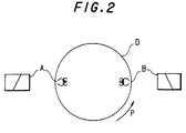
- FIG. 2 One embodiment of the magnetic head assembly which may be used for recording heads 11 or reproducing heads 13 is illustrated in FIG. 2.
- Heads A and B are mounted on a rotary drum D and are spaced apart from each other by an angular distance of 180°. It is seen that heads A and B exhibit different azimuth angles such that when signals which were recorded by, for example, head A are reproduced by head B, the phenomenon of azimuth loss minimizes the amplitude of such reproduced signals. Hence, azimuth loss is relied upon to minimize cross-talk pickup when, for example, head A scans a track during a reproducing operation that previously had been recorded by head A and picks up cross-talk components from adjacent tracks that had been recorded by head B.
- magnetic tape 12 is deployed about drum D by an angular amount of approximately 180° such that, with each rotation of the drum, heads A and B scan successive traces, or tracks, across the tape.
- tape 12 is driven about the periphery of drum D at an angle to the longitudinal axis of the drum.
- FIG. 3 schematically illustrates the track pattern formed by heads A and B of FIG. 2 when recording digital video signals on tape 12.
- the video signal is an NTSC signal and one frame is recorded in 10 tracks T0, T1, ...T9.
- head A of FIG. 2 records even tracks T0, T2, T4, ... and head B records odd tracks T1, T3, ...T9.
- Magnetic tape MT is driven from right-to-left in FIG. 3 and heads A and B scan alternate tracks in the direction indicated by the head scanning arrow.
- FIG. 4 schematically illustrates another embodiment of the magnetic head assembly of which recording heads 11 and reproducing heads 13 may be constructed.
- the embodiment shown in FIG. 4 is referred to herein as a "double azimuth head assembly" wherein heads A and B are disposed in a common support, spaced from each other by a very small angular amount and exhibit a step relationship, whereby head B is displaced from head A in a direction parallel to the longitudinal axis of drum D by an amount D s .
- Heads A and B are mounted on drum D and rotate to scan adjacent tracks simultaneously. It is appreciated that the displacement D s of heads A and B defines the track pitch T p of such adjacent tracks.
- Heads A and B exhibit respectively different azimuth angles for the same reason as mentioned hereinabove with respect to FIG. 2. It is recognized that, during recording, digital video signals are supplied simultaneously to heads A and B for simultaneous recording in adjacent tracks.
- the magnetic tape is deployed about the periphery of drum D by an amount substantially greater than 180° and, preferably, greater than 300°.
- the recording of simultaneous tracks by the head assembly shown in FIG. 4 is known to those of ordinary skill in the art.
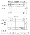
- FIG. 5A there is illustrated the manner in which the digital video samples, or pixels, of the luminance component Y are arranged into data blocks, each comprised of an 8 x 8 array of pixels.
- data blocks each comprised of an 8 x 8 array of pixels.
- 720 samples in a horizontal line and 480 samples in the vertical direction are provided. It is appreciated, then, that an array of 90 x 60 data blocks constitute a frame of luminance samples.
- the video signal is comprised of a red color difference component R-Y and a blue color difference component B-Y.
- a suitable video display is provided if the number of samples of the color difference component is one-fourth the number of samples of the luminance component.
- FIG. 5B illustrates the data blocks of R-Y and B-Y samples, each data block being comprised of an 8 x 8 array, and the number of the data blocks included in a frame is seen to be a 22.5 x 60 array of color difference data blocks. That is, the blocks of color difference samples are arranged in 60 rows of color difference data blocks, with each row consisting of 22.5 data blocks.
- FIG. 5C illustrates the construction of a macro block, and it is seen that each macro block is formed of four luminance data blocks, one R-Y data block and one B-Y data block. This construction is known as the 4:1:1 arrangement, for obvious reasons.
- Each luminance and color difference data block is subjected to orthogonal transformation, preferably discrete cosine transformation, in DCT circuit 4, quantized and variable length encoded in encoding circuit 5.
- orthogonal transformation preferably discrete cosine transformation
- DCT circuit 4 quantized and variable length encoded in encoding circuit 5.
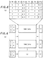
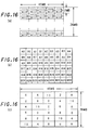
- FIG. 6A schematically illustrates a frame formed of five macro blocks, each macro block having the format schematically shown in FIG. 5C.
- each transformed, quantized and variable length encoded luminance data block is comprised of 14 bytes and each color difference data block is comprised of 9 bytes.
- the 14 bytes of a luminance data block includes motion information of the orthogonally transformed data as well as information representing the amount of high frequency components included in the orthogonally transformed data block.
- the 9 bytes included in the color difference data block includes information representing the motion of the orthogonally transformed data and information representing the amount of high frequency components included in the orthogonally transformed data block.
- Each data block also includes information representing the quantizing step used to quantize the luminance and color difference data in that block.
- each data block exhibits a variable data length by reason of the variable length coding thereof, the overall length of the data included in 30 data blocks is fixed.
- 6 data blocks constitute one macro block and 5 macro blocks constitute one data frame formed by framing circuit 6.
- parity generator 7 also adds vertical parity data C2, as shown in FIG. 6B.
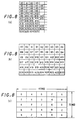
- a frame of digital video signals is formed of a 22.5 x 60 array of macro blocks. This array is shown in FIG. 7.
- a group of macro blocks consisting of, for example, 18 macro blocks, is selected as represented by the arrows shown in FIG. 7.
- FIG. 8A illustrates this group of 18 macro blocks and, for purposes of identification, these 18 macro blocks are identified as blocks A0, A1, ...A4, B0, B1, ...B4, A5, ...A8, B5, ...B8.
- Another group of 18 macro blocks is seen to be formed of macro blocks A9, A10 ...A13, B9, B10 ...B13, A14 ...A17, B14 ...B17.
- the three groups of macro blocks shown in FIG. 8A which consist of 54 macro blocks, are arranged in a 9 x 6 array, as shown in FIG. 8B. Simply for purposes of identification, the pattern shown in FIG. 8B for these three groups of macro blocks is identified as sub-area 0.
- the next three groups of macro blocks which are vertically disposed directly beneath the three groups shown in FIG. 8A are arranged in a pattern similar to that shown in FIG. 8B, and this pattern is identified as sub-area 2.
- Succeeding patterns of macro blocks, each formed of three groups are arranged in the manner shown in FIG. 8B and are identified as sub-areas 4, 6 and 8. Then, this process is repeated for the next groups of macro blocks disposed to the right of the macro blocks just discussed, and these successive patterns are shown in FIG.
- each sub-area is formed as a 9 x 6 array, and each array is identified with one of five different sub-area reference numerals 0, 2, 4, 6 and 8. These reference numerals are used for shuffling, as will now be described.
- FIG. 9 illustrates the patterns of macro blocks which are recorded in each track.
- ten tracks constitute a frame; and as shown in FIG. 9, odd frames and even frames of video data alternate.
- the head scanning direction and the tape movement direction are illustrated by respective arrows, resulting in tracks which are successively formed from the bottom to the top of FIG. 9.
- Each track identified as track A is recorded by head A and each track identified as track B is recorded by head B. It is recalled that these heads exhibit different azimuth angles and may be spaced apart by 180° (as shown in FIG. 2) or may be formed as a double azimuth head assembly (as shown in FIG. 4).
- FIG. 9 illustrates each portion as being identified by two identifiers, a numeral followed by a letter and numeral combination.
- tracks A, B, A, B, A, B, etc. are divided into portions 0-A0, 0-A1, ...0-A26; 0-B0, 0-B1, ...0-B26; 2-A0, 2-A1, ...2-A26; ...8-B0, 8-B1, ...8-B26.
- Portion 0-A0 of the first track A is formed of the macro blocks A0 in each of the five sub-areas of FIG. 8C identified as sub-area 0.
- macro block A0 in sub-area 0 in the middle column of FIG. 8C is selected in the following order: macro block A0 in sub-area 0 in the middle column of FIG. 8C, followed by macro block A0 in sub-area 0 in the column to the right of the middle column, followed by macro block A0 in sub-area 0 in the column to the left of the middle column, followed by macro block A0 in sub-area 0 in the right-most column, followed by macro block A0 in sub-area 0 in the left-most column.
- the next portion 0-A1 in the first track A is formed of five macro blocks A1 selected from each sub-area 0 in the pattern shown in FIG. 8C.
- macro block A1 from sub-area 0 in the middle column is followed by macro block A1 in sub-area 0 to the right of the middle column, followed by macro block A1 from sub-area 0 in the column to the left of the middle column, followed by macro block A1 from sub-area 0 in the right-most column, followed by macro block A1 from sub-area 0 in the left-most column.
- This selection of macro blocks A0, A1, A2, ...A26 from sub-area 0 continues, thus forming the first track A.
- Next adjacent track B is formed of macro blocks B0, B1, ...B26 selected from each sub-area 0 in the pattern shown in FIG. 8C in the same manner as macro blocks A0-A26 were selected from sub-areas 0.
- This selection operation continues, thus forming the ten tracks which may be identified as A0, B0, A2, B2, ...A8, B8.
- the frame of macro blocks shown in FIG. 7 is recorded on successive tracks in shuffled form, as just described.
- the order of the macro blocks formed in tracks A, B, A, etc. in an odd frame is interchanged in an even frame, wherein macro blocks B are recorded in tracks A and macro blocks A are recorded in tracks B.
- the macro block identification remains the same as that shown in FIGS. 8A and 8B.
- macro blocks which are vertically adjacent each other in the video frame, as shown in FIGS. 7 and 8A are recorded in adjacent tracks.
- those macro blocks which are recorded in odd tracks (e.g. tracks B) in an odd frame are recorded in even tracks (e.g. tracks A) in an even frame.
- FIG. 9 wherein macro blocks B are recorded in odd tracks B in the odd frame, yet macro blocks B are recorded in even tracks A in the even frame.
- macro blocks which are horizontally adjacent each other in the video frame, as shown in FIGS. 7 and 8A are separated from each other in a track by four macro blocks.
- portion 0-A0 in track A in the odd frame in FIG. 9 contains macro block A0
- macro block A1 which is horizontally adjacent macro block A0 in FIG. 8A, is recorded five macro blocks later in portion 0-A1 of track A.
- FIG. 10 The foregoing is represented by FIG. 10.
- Shuffling in the aforementioned manner provides error prevention in the event of, for example, head clog or damage to the tape, such as a scratch.
- head B in FIG. 2 or 4
- head B suffers from head clog. Consequently, and as is apparent from FIG. 9, in an odd frame, data which normally would be reproduced by head B will not be readily detected. That is, macro blocks B0, B1, ...B26 in all of the sub-areas may not be readily reproduced.
- head A reproduces macro blocks B0, B1, ...B26 which, of course, will be accurately recovered.
- the data from those macro blocks which are not reproduced from an odd frame nevertheless are interpolated from the data which is successfully recovered from the even frame, thereby permitting an acceptable video image to be produced.
- the tape transport speed for reproducing an NTSC signal at relatively high speeds is 5n ⁇ 0.5 times normal speed (wherein n is an integer other than 0).
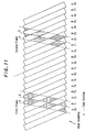
- FIG. 11 A schematic representation of the relationship between traces scanned by the double azimuth head assembly while the tape is transported at this speed and the previously recorded record tracks is illustrated in FIG. 11.
- the horizontal hatching shown in FIG. 11 represents those portions of tracks A which are picked up by head A and those portions of tracks B which are picked up by head B in a first video frame.
- head A When the heads begin a second scanning operation, head A is positioned over track T1 and head B is positioned over track T2 in the second frame; and at the end of this second scanning operation, head A is positioned over tracks T5 and T6 and head B is positioned over tracks T6 and T7.
- head A when the heads begin a third scanning operation, head A is positioned over track T2 in the third frame and head B is positioned over track T3; and at the end of this third scanning operation, head A is positioned over tracks T6 and T7 and head B is positioned over tracks T7 and T8.
- the macro blocks which appear in this emulated track T' are a composite assembly of macro blocks recovered by head A from a first frame linked to macro blocks recovered by head B from a second frame linked to macro blocks recovered by head A from a third frame linked to macro blocks recovered by head B from a fourth frame. Since the video signals of successive frames exhibit high correlation, that is, since successive frames of an image are highly correlated, the resultant image which is reproduced from the emulated, composite tracks appears as a natural image. It also will be recognized that adjacent macro blocks in a frame, such as shown in FIGS. 7 and 8A, are recorded in adjacent tracks, as shown in FIG. 9, and are recovered from such adjacent tracks when assembling a composite track which emulates a record track.
- the second scan of the double azimuth head assembly begins at the third frame of video data and not, as shown in FIG. 11, at the second frame. Also, if the tape transport speed is -4.5 times normal speed, that is, if a fast reverse reproducing operation is effected, the tracks which are scanned by the double azimuth head assembly at successive scanning operations are advanced by one track relative to the tracks which were scanned in the previous scanning operation. And if the tape transport speed is equal to -5.5 times normal speed, the scanning of tracks by the double azimuth head assembly at successive scans is delayed by one track, similar to the delay produced when the tape transport speed is equal to +4.5 times normal speed.
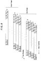
- FIG. 13 schematically illustrates the scanning of the previously recorded record tracks by heads A and B at this high reproducing speed.
- horizontal hatched areas represent those portions recovered by heads A and B from tracks A and B, respectively, in a first frame; and vertical hatching represents those portions recovered by heads A and B from tracks A and B, respectively, in a succeeding, second frame.
- head A If head A is positioned at track T0 when it begins its scanning operation in a first frame, this scanning operation ends with head A positioned over tracks T4 and T5. Then, head B begins its scanning operation positioned at tracks T5 and T6 and ends that scanning operation positioned over track T9 of the first frame as well as track T0 of the succeeding, second frame. Then, in the next-following, or second scanning operation of the heads, head A begins its scanning of the second frame positioned over tracks T0 and T1 and ends its scan positioned over tracks T4 and T5. Head B begins its scan positioned over track T6 and ends its scan positioned over tracks T0 and T1 in the third frame (not shown).
- head A When the head assembly begins its third scanning operation, head A begins its scan positioned over track T1 in the third frame and ends its scan positioned over tracks T5 and T6.
- the tracks which are scanned by the 180° spaced-apart heads are advanced by one track. That is, if head A, for example, begins its scanning operation of the first frame at track T0, this same head begins its scanning operation at track T1 of the third frame.
- emulated track T' is formed from data picked up by, for example, head A from a portion of the track scanned thereby in the first frame, and this data is linked to data picked up by head A when scanning a track in the third frame, and this data is linked to data picked up by head A when scanning a track in the fifth frame.
- the remaining data in emulated track T' is picked up by head A when the head scans the seventh frame and, possibly, when the head scans the ninth frame.
- one emulated track is formed as a composite of data picked up from tracks scanned in successive odd frames and the next adjacent track is formed as a composite from data which is picked up from the scanning of tracks in successive even frames.
- the head assembly is formed of 180° spaced-apart heads
- macro blocks which are adjacent each other in a frame, as shown in FIGS. 7 and 8A, and are recorded in adjacent tracks, as shown in FIG. 9, are recovered from such adjacent tracks, similar to the arrangement wherein the double azimuth head assembly is used to perform the high speed reproducing operation.
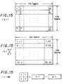
- FIG. 15A there is illustrated the manner in which the digital video samples of the luminance component Y are arranged into data blocks when the video signal conforms with the PAL standard.
- a PAL frame 720 samples in a horizontal line and 576 samples in the vertical direction are provided. It is appreciated, then, that an array of 90 x 72 data blocks constitute a frame of PAL luminance samples.
- FIG. 15B illustrates the data blocks of R-Y and B-Y samples, each data block being comprised of an 8 x 8 array, and the number of data blocks included in a frame is seen to be a 45 x 36 array of color difference data blocks. That is, the blocks of color difference samples are arranged in 36 rows of color difference data blocks, with each row consisting of 45 color difference data blocks.
- FIG. 15C illustrates the construction of a macro block which is formed of four luminance data blocks, one R-Y data block and one B-Y data block.
- this construction is known as the 4:2:0 arrangement.
- each luminance and color difference data block in the PAL format is subjected to orthogonal transformation, quantization, variable encoding, framing, and the remaining processing discussed above in connection with FIG. 1.
- FIG. 16A illustrates a frame of macro blocks formed of a 45 x 36 array of the macro blocks similar to that shown in FIG. 15B.
- a group of macro blocks consisting of, for example, 18 macro blocks, is selected for shuffling; and as is seen in FIG. 16A, this group is formed of a 9 x 2 array.
- the group of 18 macro blocks in the upper left-hand corner of FIG. 16A consists of macro blocks A0, B0, ...A8, B8.
- a group of 18 macro blocks immediately below the first-mentioned group consists of macro blocks A9, B9, ...A17, B17.
- a third group of 18 macro blocks immediately below the aforementioned second group consists of macro blocks A18, B18, ...A26, B26.
- FIG. 16B illustrates a set of these three groups of macro blocks A0-B26, formed of 54 macro blocks.
- another set of 54 macro blocks vertically disposed beneath the set shown in FIGS. 16A and 16B may be selected, and a total of six sets of macro blocks, each set being formed of a 9 x 6 array (as shown in FIG. 16B) constitute one column of the macro blocks shown in FIG. 16C.
- Another column formed of six sets of macro blocks, each set consisting of a 9 x 6 array similar to that shown in FIG. 16B, is adjacent the first-mentioned column, and a total of five columns, each column being formed of six sets and each set consisting of a 9 x 6 array of macro blocks thus constitutes the frame shown in FIG. 16A.
- FIG. 16C illustrates the aforementioned five columns of macro blocks, and each set in each column is identified by a respective sub-area identifier 0, 2, 4, 6, 8 or 10. These sub-area identifiers, arranged in the order shown in FIG. 16C, thus identify each sub-area formed of a 9 x 6 array of macro blocks. It is appreciated that FIG. 16C is similar to FIG. 8C.
- each track of FIG. 17 is divided into 27 portions, and each portion has recorded therein those macro blocks in each sub-area identified by the same sub-area identifier and limited to similarly identified macro blocks.
- each sub-area in FIG. 16C includes macro blocks A0-B26. That is, each sub-area identified by identifier 0 contains macro blocks A0-B26. Likewise, each sub-area identified by identifier 2 contains macro blocks A0-B26.
- FIG. 16C includes macro blocks A0-B26.
- the first track A includes all of the macro blocks A0, A1, ...A26 included in all of the sub-areas identified by identifier 0.
- the first track B includes therein all of the macro blocks B0, B1, ...B26 included in each sub-area identified by identifier 0.
- the second track A includes therein macro blocks A0, A1, ...A26 included in each sub-area identified by identifier 2.
- the remaining tracks B, A, B, A, ...B are similarly formed.
- the macro blocks which are recorded in each portion of each track are selected as follows: first, macro block A0 (or B0) from sub-area 0 included in the central column shown in FIG. 16C, followed by macro block A0 included in sub-area 0 to the right of the central column, followed by macro block A0 included in sub-area 0 to the left of the central column, followed by macro block A0 included in the right-most sub-area 0 followed by macro block A0 included in the left-most sub-area 0.
- This order of recording macro blocks in a track is repeated for macro blocks A1, A2, ...A26 recorded in portions 0-A1, 0-A2, ...0-A26, respectively.
- macro blocks B0 from each of sub-area 0 are recorded in the following order: first from sub-area 0 in the central column, then from sub-area 0 in the adjacent right column, then from sub-area 0 in the adjacent left column, then from sub-area 0 in the right-most column, then from sub-area 0 in the left-most column.
- the twelve tracks which constitute a frame in the PAL format are recorded with macro blocks as illustrated in FIG. 17.
- one image frame may be displayed as a natural display if the transport speed is restricted as follows: if the video data is reproduced by a double azimuth head assembly, such as shown in FIG. 4, the tape transport speed should be 6n ⁇ 0.5 times normal speed, wherein n is an integer other than 0. If the video data is reproduced by heads which are spaced apart by 180°, as shown in FIG. 2, the tape transport speed should be 6n ⁇ 0.25 times normal speed, wherein n is an odd integer and may be positive or negative, depending upon whether the tape is transported in the forward or reverse direction.
- the reason for displaying an image which appears natural when the tape is transported at the aforementioned speeds is similar to the reason discussed hereinabove in detail in connection with the high speed reproduction of NTSC data; and in the interest of brevity, that explanation is not repeated here.
- the composite tracks which are emulated by reproducing data from only portions of tracks, such as shown in FIGS. 12 and 14, may include data which is not linked.
- the tracks shown in FIG. 11 are reproduced at a tape transport speed that is 5.5 times normal speed by a double azimuth head assembly; but let it be further assumed that the read-out rate of the reproduced data is about 35%. Because of this low read-out rate, the composite tracks which are emulated do not appear as shown in FIG.
- Emulated track T' in FIG. 12 corresponds to emulated track T' in FIG. 18.
- data recovered from successive frames appear in areas which abut each other in track T' of FIG. 12, those same areas are seen to be spaced from each other in track T' in FIG. 18.
- the spacings between such areas in which data from successive frames are assembled is seen to be triangular in shape. Examples of these triangles are shown as triangles a, b, c, d and e.
- triangles a-e appear smaller; and if the data read-out rate is on the order of, for example, 50%, the triangles are sufficiently small such that the successive areas in, for example, track T' which include data recovered from successive frames abut each other. That is, when the data read-out rate is on the order of about 50% (or greater), the data recovered from portions of tracks in different frames are linked and more closely resemble the linked data shown in FIG. 12. However, if the data read-out rate is less than 50%, it is likely that the data recovered from different tracks in successive frames are not linked.
- the tape is transported at 6n ⁇ 0.25 times normal speed (wherein n is an odd integer) when a double azimuth head assembly is used; and the tape is transported at 6n ⁇ 0.125 times normal speed (wherein n is an odd number) when the heads are spaced apart by 180°.
- n is an odd integer
- the tape transport speeds are selected, a natural-looking image may be displayed even if the data read-out rate is as low as 25%.
- NTSC video data is reproduced at a high-speed reproducing operation by a double azimuth head assembly and that the data read-out rate is on the order of about 35%. Accordingly, the magnetic tape is transported at a speed 5.25 times normal speed. At this speed, it will be appreciated that a track scanned by a head is advanced by 1/2 track pitch at each successive scanning operation. Consequently, and as shown in FIG. 19, the data which is recovered from those portions of the respective tracks in successive frames will appear as a composite assembly emulating the recording tracks.
- emulated track T' it is seen from, for example, emulated track T', that a portion of the data which is recovered from a track scanned in the first frame overlaps with a portion of the data recovered from a track scanned in the second frame; and this data overlaps with a portion of the data reproduced from a track scanned in the third frame. That is, the composite video data which is assembled in emulated track T' is seen to be linked from frame to frame and also to be partially overlapped from frame to frame. The use of time delays in the reproducing channels may be used to compensate for such overlapping.
- the magnetic tape is transported at a speed 5.125 times normal speed.
- the data read-out rate is on the order of about 35%.
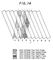
- emulated track T' which is formed of the composite assembly of data reproduced from portions of tracks included in successive frames. It is seen that the composite assembly of FIG. 20 is similar to that shown in FIG. 14, except that, in FIG. 20, the data which is reproduced from a track in the first frame is linked to and overlaps with data which is reproduced from a track in the third frame and this, in turn, is linked to and overlaps with data which is reproduced from a track in the fifth frame.
- the track scanned by a head is advanced by one track pitch at every third scanning operation, and this is similar to the operation discussed hereinabove in conjunction with FIG. 13.
- an emulated track data recovered from tracks in every other frame are linked.
- emulated track T' data recovered from tracks in the odd frames are linked
- emulated track adjacent track T' data recovered from tracks in even frames are linked.
- the tape is transported at a speed equal to 6n ⁇ 0.25 times normal speed when a double azimuth head assembly is used; and the tape is transported at a speed equal to 6n ⁇ 0.125 times normal speed (n is an odd number) when the head assembly is comprised of heads which are spaced apart by 180°.
- the tape transport speed is equal to m x n ⁇ 0.25 times normal speed when the data read-out rate is not less than 50%, and the tape transport speed is equal to m x n ⁇ 0.125 times normal speed when the data read-out rate is less than 50%; wherein n is an odd number.
Landscapes
- Engineering & Computer Science (AREA)
- Signal Processing (AREA)
- Multimedia (AREA)
- Databases & Information Systems (AREA)
- Television Signal Processing For Recording (AREA)
- Signal Processing For Digital Recording And Reproducing (AREA)
Claims (9)
- Appareil pour reproduire des signaux vidéo numériques à partir d'une bande magnétique (12), dans lequel une trame de signaux vidéo numériques a été enregistrée dans 2m pistes, m étant un entier supérieur à 1, lorsque ladite bande magnétique a été transportée à une première vitesse, chaque trame ayant été divisée selon des blocs d'éléments d'image, ledit appareil présentant un certain taux de lecture de données et comprenant :caractérisé en ce que :deux têtes tournantes (A, B) séparées angulairement l'une de l'autre de 180° et admettant des angles d'azimut respectivement différents ; etun moyen de transport de bande pour transporter ladite bande magnétique à une seconde vitesse,ladite seconde vitesse est égale à (m x n ± I) fois ladite première vitesse où n est un entier impair, I = 0,25 lorsque ledit taux de lecture de données est d'au moins 50 % et I = 0,125 lorsque ledit taux de lecture de données est inférieur à 50 %.
- Appareil pour reproduire des signaux vidéo numériques à partir d'une bande magnétique (12), dans lequel une trame de signaux vidéo numériques a été enregistrée dans 2m pistes, m étant un entier supérieur à 1, lorsque ladite bande magnétique a été transportée à une vitesse d'enregistrement, chaque trame étant divisée selon des blocs d'éléments d'image, ledit appareil présentant un certain taux de lecture de données et comprenant :caractérisé en ce que :deux têtes magnétiques tournantes (A, B) disposées selon un assemblage de têtes à deux azimuts et admettant des angles d'azimut respectivement différents ; etun moyen de transport de bande pour transporter ladite bande magnétique à une vitesse de lecture rapide,ladite vitesse de lecture rapide est égale à (m x n ± I) fois ladite vitesse d'enregistrement où n est un entier autre que zéro, I = 0,5 lorsque ledit taux de lecture de données est d'au moins 50 % et I = 0,25 lorsque ledit taux de lecture de données est inférieur à 50 %.
- Appareil selon l'une quelconque des revendications 1 et 2, dans lequel n est un nombre positif lorsque ledit moyen de transport de bande transporte ladite bande magnétique dans un sens vers l'avant et n est un nombre négatif lorsque ledit moyen de transport de bande transporte ladite bande magnétique dans un sens inverse.
- Appareil selon l'une quelconque des revendications 1 à 3, dans lequel lesdits signaux vidéo numériques sont des signaux NTSC et m = 5.
- Appareil selon l'une quelconque des revendications 1 à 3, dans lequel lesdits signaux vidéo numériques sont des signaux PAL et m = 6.
- Appareil selon l'une quelconque des revendications 1 à 3, dans lequel n est un entier impair lorsque I = 0,25.
- Appareil selon l'une quelconque des revendications 1 à 3, dans lequel la trame de signaux vidéo numériques enregistrée dans lesdites 2m pistes est constituée par des signaux vidéo transformés orthogonalement codés en code de longueur variable.
- Appareil selon la revendication 7, dans lequel ledit code de longueur variable est un code Huffman bidimensionnel.
- Appareil selon la revendication 7, dans lequel les signaux vidéo transformés orthogonalement d'une trame sont désordonnancés.
Applications Claiming Priority (4)
| Application Number | Priority Date | Filing Date | Title |
|---|---|---|---|
| JP35952292 | 1992-12-25 | ||
| JP359522/92 | 1992-12-25 | ||
| JP56576/93 | 1993-02-22 | ||
| JP5657693A JP3546434B2 (ja) | 1992-12-25 | 1993-02-22 | ビデオ信号再生装置 |
Publications (3)
| Publication Number | Publication Date |
|---|---|
| EP0603875A2 EP0603875A2 (fr) | 1994-06-29 |
| EP0603875A3 EP0603875A3 (fr) | 1995-01-04 |
| EP0603875B1 true EP0603875B1 (fr) | 1999-03-17 |
Family
ID=26397529
Family Applications (1)
| Application Number | Title | Priority Date | Filing Date |
|---|---|---|---|
| EP19930120746 Expired - Lifetime EP0603875B1 (fr) | 1992-12-25 | 1993-12-22 | Appareil de reproduction d'un signal vidéo numérique avec reproduction à grande vitesse |
Country Status (6)
| Country | Link |
|---|---|
| US (2) | US5434677A (fr) |
| EP (1) | EP0603875B1 (fr) |
| JP (1) | JP3546434B2 (fr) |
| KR (1) | KR100253041B1 (fr) |
| CA (1) | CA2112430C (fr) |
| DE (1) | DE69323973T2 (fr) |
Families Citing this family (20)
| Publication number | Priority date | Publication date | Assignee | Title |
|---|---|---|---|---|
| JPH0748503B2 (ja) * | 1988-11-29 | 1995-05-24 | 三菱電機株式会社 | 電界効果トランジスタの製造方法 |
| US6141487A (en) * | 1994-03-14 | 2000-10-31 | Matsushita Electric Industrial Co., Ltd. | Data recording/reproducing apparatus and method for high speed play |
| US5889918A (en) * | 1994-04-01 | 1999-03-30 | Kabushiki Kaisha Toshiba | Method and apparatus for recording digital picture image signals for multiple speed reproduction |
| JP3385109B2 (ja) * | 1994-04-12 | 2003-03-10 | 三菱電機株式会社 | ディジタルvtr |
| US6977964B1 (en) | 1994-04-12 | 2005-12-20 | Mitsubishi Denki Kabushiki Kaisha | Digital VTR for recording and replaying data depending on replay modes |
| JPH09511634A (ja) * | 1994-04-12 | 1997-11-18 | フィリップス エレクトロニクス ネムローゼ フェンノートシャップ | トリックモードビデオ信号の記録及び再生 |
| BR9507357A (pt) | 1994-04-13 | 1997-09-16 | Rca Thomson Licensing Corp | Método para a gravação de um sinal representativo da imagem de vídeo digital em uma fita magética tendo um formato de trilha varrida helicoidalmente fita magnética para uso em gravador vídeo cassete digital gravada com um sinal digital que representa um sinal de imagem digital tendo um formato MPEG compatível o dito sinal digital sendo gravado na dita fita em trilhas sucessivas a método para determinar um local gravado de um sinal representativo de imagem de video digital em um fita magnética tendo um formato de trilha varrida helicoidalmente |
| DE69519539T2 (de) * | 1994-05-24 | 2001-04-05 | Victor Company Of Japan, Ltd. | Anlage zum Aufnehmen und Wiedergeben von bewegten Bildern |
| JP3330459B2 (ja) * | 1994-07-04 | 2002-09-30 | 三菱電機株式会社 | 磁気記録再生装置 |
| JP3579926B2 (ja) * | 1994-08-25 | 2004-10-20 | ソニー株式会社 | デジタルビデオ信号の再生方法及び再生装置 |
| US5754699A (en) * | 1994-11-24 | 1998-05-19 | Victor Company Of Japan, Ltd. | Method of reducing mosquito noise generated during decoding process of image data and device for decoding image data using the same |
| KR0129947B1 (ko) * | 1994-12-30 | 1998-04-18 | 김광호 | 트릭플레이를 위한 디지탈 비디오 테이프의 기록 및 재생방법 |
| KR100298241B1 (ko) * | 1995-03-07 | 2001-10-24 | 모리시타 요이찌 | 기록재생장치 |
| JP2000500946A (ja) * | 1996-01-19 | 2000-01-25 | フィリップス エレクトロニクス ネムローゼ フェンノートシャップ | 記録担体上の傾斜トラックへのデータ削減デジタルビデオ信号の記録 |
| JP3921841B2 (ja) * | 1998-10-16 | 2007-05-30 | ソニー株式会社 | 信号処理装置および方法、ならびに、記録装置、再生装置および記録再生装置 |
| JP3932721B2 (ja) * | 1999-05-14 | 2007-06-20 | ソニー株式会社 | データ記録装置、データ記録再生装置、データ記録方法およびデータ記録再生方法 |
| JP3903654B2 (ja) * | 1999-08-05 | 2007-04-11 | ソニー株式会社 | データ伝送装置及びデータ伝送方法 |
| JP3645458B2 (ja) * | 1999-11-29 | 2005-05-11 | 松下電器産業株式会社 | 情報記録再生装置 |
| JP2003519990A (ja) * | 1999-12-29 | 2003-06-24 | コーニンクレッカ フィリップス エレクトロニクス エヌ ヴィ | 画像を符号化及び復号化する装置 |
| US10102875B1 (en) * | 2017-07-31 | 2018-10-16 | Oracle International Corporation | Servo pattern for precise tracking in optical tapes |
Family Cites Families (9)
| Publication number | Priority date | Publication date | Assignee | Title |
|---|---|---|---|---|
| JPS62234478A (ja) * | 1986-04-04 | 1987-10-14 | Matsushita Electric Ind Co Ltd | 映像信号の記録再生装置 |
| US5214515A (en) * | 1986-10-28 | 1993-05-25 | Mitsubishi Denki Kabushiki Kaisha | Video signal recording/reproducing apparatus |
| JP2570377B2 (ja) * | 1988-04-07 | 1997-01-08 | ソニー株式会社 | 磁気記録および/または再生装置 |
| JP2720477B2 (ja) * | 1988-10-18 | 1998-03-04 | ソニー株式会社 | 映像信号再生装置 |
| JP2760112B2 (ja) * | 1989-12-14 | 1998-05-28 | キヤノン株式会社 | 再生装置 |
| EP0471118B1 (fr) * | 1990-08-13 | 1995-12-20 | Matsushita Electric Industrial Co., Ltd. | Appareil numérique d'enregistrement et de reproduction d'un signal vidéo |
| EP0509594B1 (fr) * | 1991-04-18 | 1997-10-22 | Koninklijke Philips Electronics N.V. | Système et procédé pour améliorer le fonctionnement d'un magnétoscope en mode de recherche |
| JPH0574110A (ja) * | 1991-09-12 | 1993-03-26 | Sony Corp | デイジタルvtr |
| JP3093494B2 (ja) * | 1992-11-18 | 2000-10-03 | 株式会社東芝 | 多様性信号処理装置 |
-
1993
- 1993-02-22 JP JP5657693A patent/JP3546434B2/ja not_active Expired - Fee Related
- 1993-12-22 EP EP19930120746 patent/EP0603875B1/fr not_active Expired - Lifetime
- 1993-12-22 DE DE69323973T patent/DE69323973T2/de not_active Expired - Fee Related
- 1993-12-23 US US08/172,197 patent/US5434677A/en not_active Ceased
- 1993-12-24 KR KR1019930030162A patent/KR100253041B1/ko not_active Expired - Fee Related
- 1993-12-24 CA CA 2112430 patent/CA2112430C/fr not_active Expired - Fee Related
-
1997
- 1997-07-16 US US08/895,597 patent/USRE37810E1/en not_active Expired - Lifetime
Also Published As
| Publication number | Publication date |
|---|---|
| DE69323973T2 (de) | 1999-07-22 |
| USRE37810E1 (en) | 2002-07-30 |
| JPH06245184A (ja) | 1994-09-02 |
| CA2112430C (fr) | 2003-05-06 |
| DE69323973D1 (de) | 1999-04-22 |
| JP3546434B2 (ja) | 2004-07-28 |
| EP0603875A2 (fr) | 1994-06-29 |
| KR100253041B1 (ko) | 2000-05-01 |
| US5434677A (en) | 1995-07-18 |
| CA2112430A1 (fr) | 1994-06-26 |
| EP0603875A3 (fr) | 1995-01-04 |
| KR940015977A (ko) | 1994-07-22 |
Similar Documents
| Publication | Publication Date | Title |
|---|---|---|
| EP0603875B1 (fr) | Appareil de reproduction d'un signal vidéo numérique avec reproduction à grande vitesse | |
| US5404249A (en) | Digital video tape recorder with data block ID signal error correction | |
| JP2664112B2 (ja) | 映像信号のディジタル記録及び再生装置 | |
| JP3322998B2 (ja) | ディジタルvtr | |
| JP2952192B2 (ja) | ディジタルビデオデータ記録/再生方法及びその装置 | |
| CA2133710C (fr) | Methode d'enregistrement et de lecture a bande magnetique produisant des effets speciaux dans les signaux video numeriques | |
| JP2708312B2 (ja) | 記録装置及び再生装置 | |
| JPH0486183A (ja) | 映像信号の記録再生装置 | |
| JP3008995B2 (ja) | ディジタルビデオ信号の磁気記録装置 | |
| JPH041557B2 (fr) | ||
| EP0575997B1 (fr) | Dispositif de traitement de signal d'un enregistreur à cassette vidéo numérique | |
| US5414566A (en) | Apparatus and method for generating high speed dubbing signal | |
| JP3348288B2 (ja) | ディジタルビデオ信号の記録方法および装置 | |
| US6192182B1 (en) | Digital information signal recording apparatus and method thereof | |
| JP3106479B2 (ja) | ディジタルコンポーネント信号の記録装置及び記録方法 | |
| JPH0898144A (ja) | 映像データの誤り訂正方式 | |
| JP3232731B2 (ja) | デジタル情報記録再生装置 | |
| JP3336745B2 (ja) | デジタル磁気記録及び/又は再生装置 | |
| JP3259298B2 (ja) | ディジタル画像信号の記録装置 | |
| JPH11164261A (ja) | ディジタルビデオ信号処理装置およびディジタルビデオ信号再生装置 | |
| JP2664987B2 (ja) | ディジタルビデオ信号記録装置 | |
| JPS5888980A (ja) | テレビジヨン画像信号の記録再生方式 | |
| JPH04217197A (ja) | ディジタルビデオ記録再生装置 | |
| JPH0795512A (ja) | 記録再生装置 | |
| JPH0530470A (ja) | デイジタルビデオ信号の記録および/または再生方法 |
Legal Events
| Date | Code | Title | Description |
|---|---|---|---|
| PUAI | Public reference made under article 153(3) epc to a published international application that has entered the european phase |
Free format text: ORIGINAL CODE: 0009012 |
|
| AK | Designated contracting states |
Kind code of ref document: A2 Designated state(s): DE FR GB NL |
|
| PUAL | Search report despatched |
Free format text: ORIGINAL CODE: 0009013 |
|
| AK | Designated contracting states |
Kind code of ref document: A3 Designated state(s): DE FR GB NL |
|
| 17P | Request for examination filed |
Effective date: 19950627 |
|
| 17Q | First examination report despatched |
Effective date: 19970902 |
|
| GRAG | Despatch of communication of intention to grant |
Free format text: ORIGINAL CODE: EPIDOS AGRA |
|
| GRAG | Despatch of communication of intention to grant |
Free format text: ORIGINAL CODE: EPIDOS AGRA |
|
| GRAH | Despatch of communication of intention to grant a patent |
Free format text: ORIGINAL CODE: EPIDOS IGRA |
|
| GRAH | Despatch of communication of intention to grant a patent |
Free format text: ORIGINAL CODE: EPIDOS IGRA |
|
| GRAA | (expected) grant |
Free format text: ORIGINAL CODE: 0009210 |
|
| AK | Designated contracting states |
Kind code of ref document: B1 Designated state(s): DE FR GB NL |
|
| RIN1 | Information on inventor provided before grant (corrected) |
Inventor name: JAPAN, CHIBA, C/O SONY CORPORATION Inventor name: OIKAWA, YUKA, C/O SONY CORPORATION |
|
| REF | Corresponds to: |
Ref document number: 69323973 Country of ref document: DE Date of ref document: 19990422 |
|
| ET | Fr: translation filed | ||
| PLBE | No opposition filed within time limit |
Free format text: ORIGINAL CODE: 0009261 |
|
| STAA | Information on the status of an ep patent application or granted ep patent |
Free format text: STATUS: NO OPPOSITION FILED WITHIN TIME LIMIT |
|
| 26N | No opposition filed | ||
| REG | Reference to a national code |
Ref country code: GB Ref legal event code: IF02 |
|
| PGFP | Annual fee paid to national office [announced via postgrant information from national office to epo] |
Ref country code: NL Payment date: 20081203 Year of fee payment: 16 |
|
| PGFP | Annual fee paid to national office [announced via postgrant information from national office to epo] |
Ref country code: FR Payment date: 20081212 Year of fee payment: 16 |
|
| PGFP | Annual fee paid to national office [announced via postgrant information from national office to epo] |
Ref country code: DE Payment date: 20081219 Year of fee payment: 16 |
|
| PGFP | Annual fee paid to national office [announced via postgrant information from national office to epo] |
Ref country code: GB Payment date: 20081217 Year of fee payment: 16 |
|
| REG | Reference to a national code |
Ref country code: NL Ref legal event code: V1 Effective date: 20100701 |
|
| GBPC | Gb: european patent ceased through non-payment of renewal fee |
Effective date: 20091222 |
|
| REG | Reference to a national code |
Ref country code: FR Ref legal event code: ST Effective date: 20100831 |
|
| PG25 | Lapsed in a contracting state [announced via postgrant information from national office to epo] |
Ref country code: NL Free format text: LAPSE BECAUSE OF NON-PAYMENT OF DUE FEES Effective date: 20100701 Ref country code: FR Free format text: LAPSE BECAUSE OF NON-PAYMENT OF DUE FEES Effective date: 20091231 |
|
| PG25 | Lapsed in a contracting state [announced via postgrant information from national office to epo] |
Ref country code: DE Free format text: LAPSE BECAUSE OF NON-PAYMENT OF DUE FEES Effective date: 20100701 |
|
| PG25 | Lapsed in a contracting state [announced via postgrant information from national office to epo] |
Ref country code: GB Free format text: LAPSE BECAUSE OF NON-PAYMENT OF DUE FEES Effective date: 20091222 |