EP0603902A2 - Flussigkeitstrahlkopf und Vorrichtung dafür - Google Patents
Flussigkeitstrahlkopf und Vorrichtung dafür Download PDFInfo
- Publication number
- EP0603902A2 EP0603902A2 EP93120835A EP93120835A EP0603902A2 EP 0603902 A2 EP0603902 A2 EP 0603902A2 EP 93120835 A EP93120835 A EP 93120835A EP 93120835 A EP93120835 A EP 93120835A EP 0603902 A2 EP0603902 A2 EP 0603902A2
- Authority
- EP
- European Patent Office
- Prior art keywords
- liquid
- filter
- receiving member
- jet head
- annular
- Prior art date
- Legal status (The legal status is an assumption and is not a legal conclusion. Google has not performed a legal analysis and makes no representation as to the accuracy of the status listed.)
- Granted
Links
Images


Classifications
-
- B—PERFORMING OPERATIONS; TRANSPORTING
- B41—PRINTING; LINING MACHINES; TYPEWRITERS; STAMPS
- B41J—TYPEWRITERS; SELECTIVE PRINTING MECHANISMS, i.e. MECHANISMS PRINTING OTHERWISE THAN FROM A FORME; CORRECTION OF TYPOGRAPHICAL ERRORS
- B41J2/00—Typewriters or selective printing mechanisms characterised by the printing or marking process for which they are designed
- B41J2/005—Typewriters or selective printing mechanisms characterised by the printing or marking process for which they are designed characterised by bringing liquid or particles selectively into contact with a printing material
- B41J2/01—Ink jet
- B41J2/17—Ink jet characterised by ink handling
- B41J2/175—Ink supply systems ; Circuit parts therefor
- B41J2/17563—Ink filters
-
- B—PERFORMING OPERATIONS; TRANSPORTING
- B29—WORKING OF PLASTICS; WORKING OF SUBSTANCES IN A PLASTIC STATE IN GENERAL
- B29C—SHAPING OR JOINING OF PLASTICS; SHAPING OF MATERIAL IN A PLASTIC STATE, NOT OTHERWISE PROVIDED FOR; AFTER-TREATMENT OF THE SHAPED PRODUCTS, e.g. REPAIRING
- B29C65/00—Joining or sealing of preformed parts, e.g. welding of plastics materials; Apparatus therefor
- B29C65/56—Joining or sealing of preformed parts, e.g. welding of plastics materials; Apparatus therefor using mechanical means or mechanical connections, e.g. form-fits
- B29C65/567—Joining or sealing of preformed parts, e.g. welding of plastics materials; Apparatus therefor using mechanical means or mechanical connections, e.g. form-fits using a tamping or a swaging operation, i.e. at least partially deforming the edge or the rim of a first part to be joined to clamp a second part to be joined
- B29C65/568—Joining or sealing of preformed parts, e.g. welding of plastics materials; Apparatus therefor using mechanical means or mechanical connections, e.g. form-fits using a tamping or a swaging operation, i.e. at least partially deforming the edge or the rim of a first part to be joined to clamp a second part to be joined using a swaging operation, i.e. totally deforming the edge or the rim of a first part to be joined to clamp a second part to be joined
-
- B—PERFORMING OPERATIONS; TRANSPORTING
- B29—WORKING OF PLASTICS; WORKING OF SUBSTANCES IN A PLASTIC STATE IN GENERAL
- B29C—SHAPING OR JOINING OF PLASTICS; SHAPING OF MATERIAL IN A PLASTIC STATE, NOT OTHERWISE PROVIDED FOR; AFTER-TREATMENT OF THE SHAPED PRODUCTS, e.g. REPAIRING
- B29C66/00—General aspects of processes or apparatus for joining preformed parts
- B29C66/01—General aspects dealing with the joint area or with the area to be joined
- B29C66/05—Particular design of joint configurations
- B29C66/10—Particular design of joint configurations particular design of the joint cross-sections
- B29C66/11—Joint cross-sections comprising a single joint-segment, i.e. one of the parts to be joined comprising a single joint-segment in the joint cross-section
- B29C66/112—Single lapped joints
-
- B—PERFORMING OPERATIONS; TRANSPORTING
- B29—WORKING OF PLASTICS; WORKING OF SUBSTANCES IN A PLASTIC STATE IN GENERAL
- B29C—SHAPING OR JOINING OF PLASTICS; SHAPING OF MATERIAL IN A PLASTIC STATE, NOT OTHERWISE PROVIDED FOR; AFTER-TREATMENT OF THE SHAPED PRODUCTS, e.g. REPAIRING
- B29C66/00—General aspects of processes or apparatus for joining preformed parts
- B29C66/01—General aspects dealing with the joint area or with the area to be joined
- B29C66/05—Particular design of joint configurations
- B29C66/10—Particular design of joint configurations particular design of the joint cross-sections
- B29C66/12—Joint cross-sections combining only two joint-segments; Tongue and groove joints; Tenon and mortise joints; Stepped joint cross-sections
- B29C66/122—Joint cross-sections combining only two joint-segments, i.e. one of the parts to be joined comprising only two joint-segments in the joint cross-section
- B29C66/1222—Joint cross-sections combining only two joint-segments, i.e. one of the parts to be joined comprising only two joint-segments in the joint cross-section comprising at least a lapped joint-segment
-
- B—PERFORMING OPERATIONS; TRANSPORTING
- B29—WORKING OF PLASTICS; WORKING OF SUBSTANCES IN A PLASTIC STATE IN GENERAL
- B29C—SHAPING OR JOINING OF PLASTICS; SHAPING OF MATERIAL IN A PLASTIC STATE, NOT OTHERWISE PROVIDED FOR; AFTER-TREATMENT OF THE SHAPED PRODUCTS, e.g. REPAIRING
- B29C66/00—General aspects of processes or apparatus for joining preformed parts
- B29C66/01—General aspects dealing with the joint area or with the area to be joined
- B29C66/05—Particular design of joint configurations
- B29C66/10—Particular design of joint configurations particular design of the joint cross-sections
- B29C66/12—Joint cross-sections combining only two joint-segments; Tongue and groove joints; Tenon and mortise joints; Stepped joint cross-sections
- B29C66/122—Joint cross-sections combining only two joint-segments, i.e. one of the parts to be joined comprising only two joint-segments in the joint cross-section
- B29C66/1226—Joint cross-sections combining only two joint-segments, i.e. one of the parts to be joined comprising only two joint-segments in the joint cross-section comprising at least one bevelled joint-segment
-
- B—PERFORMING OPERATIONS; TRANSPORTING
- B29—WORKING OF PLASTICS; WORKING OF SUBSTANCES IN A PLASTIC STATE IN GENERAL
- B29C—SHAPING OR JOINING OF PLASTICS; SHAPING OF MATERIAL IN A PLASTIC STATE, NOT OTHERWISE PROVIDED FOR; AFTER-TREATMENT OF THE SHAPED PRODUCTS, e.g. REPAIRING
- B29C66/00—General aspects of processes or apparatus for joining preformed parts
- B29C66/01—General aspects dealing with the joint area or with the area to be joined
- B29C66/05—Particular design of joint configurations
- B29C66/10—Particular design of joint configurations particular design of the joint cross-sections
- B29C66/13—Single flanged joints; Fin-type joints; Single hem joints; Edge joints; Interpenetrating fingered joints; Other specific particular designs of joint cross-sections not provided for in groups B29C66/11 - B29C66/12
- B29C66/135—Single hemmed joints, i.e. one of the parts to be joined being hemmed in the joint area
-
- B—PERFORMING OPERATIONS; TRANSPORTING
- B29—WORKING OF PLASTICS; WORKING OF SUBSTANCES IN A PLASTIC STATE IN GENERAL
- B29C—SHAPING OR JOINING OF PLASTICS; SHAPING OF MATERIAL IN A PLASTIC STATE, NOT OTHERWISE PROVIDED FOR; AFTER-TREATMENT OF THE SHAPED PRODUCTS, e.g. REPAIRING
- B29C66/00—General aspects of processes or apparatus for joining preformed parts
- B29C66/50—General aspects of joining tubular articles; General aspects of joining long products, i.e. bars or profiled elements; General aspects of joining single elements to tubular articles, hollow articles or bars; General aspects of joining several hollow-preforms to form hollow or tubular articles
- B29C66/51—Joining tubular articles, profiled elements or bars; Joining single elements to tubular articles, hollow articles or bars; Joining several hollow-preforms to form hollow or tubular articles
- B29C66/53—Joining single elements to tubular articles, hollow articles or bars
- B29C66/534—Joining single elements to open ends of tubular or hollow articles or to the ends of bars
- B29C66/5346—Joining single elements to open ends of tubular or hollow articles or to the ends of bars said single elements being substantially flat
-
- B—PERFORMING OPERATIONS; TRANSPORTING
- B29—WORKING OF PLASTICS; WORKING OF SUBSTANCES IN A PLASTIC STATE IN GENERAL
- B29C—SHAPING OR JOINING OF PLASTICS; SHAPING OF MATERIAL IN A PLASTIC STATE, NOT OTHERWISE PROVIDED FOR; AFTER-TREATMENT OF THE SHAPED PRODUCTS, e.g. REPAIRING
- B29C66/00—General aspects of processes or apparatus for joining preformed parts
- B29C66/70—General aspects of processes or apparatus for joining preformed parts characterised by the composition, physical properties or the structure of the material of the parts to be joined; Joining with non-plastics material
- B29C66/74—Joining plastics material to non-plastics material
- B29C66/748—Joining plastics material to non-plastics material to natural products or their composites, not provided for in groups B29C66/742 - B29C66/746
- B29C66/7487—Wood
-
- B—PERFORMING OPERATIONS; TRANSPORTING
- B29—WORKING OF PLASTICS; WORKING OF SUBSTANCES IN A PLASTIC STATE IN GENERAL
- B29C—SHAPING OR JOINING OF PLASTICS; SHAPING OF MATERIAL IN A PLASTIC STATE, NOT OTHERWISE PROVIDED FOR; AFTER-TREATMENT OF THE SHAPED PRODUCTS, e.g. REPAIRING
- B29C66/00—General aspects of processes or apparatus for joining preformed parts
- B29C66/80—General aspects of machine operations or constructions and parts thereof
- B29C66/81—General aspects of the pressing elements, i.e. the elements applying pressure on the parts to be joined in the area to be joined, e.g. the welding jaws or clamps
- B29C66/814—General aspects of the pressing elements, i.e. the elements applying pressure on the parts to be joined in the area to be joined, e.g. the welding jaws or clamps characterised by the design of the pressing elements, e.g. of the welding jaws or clamps
- B29C66/8141—General aspects of the pressing elements, i.e. the elements applying pressure on the parts to be joined in the area to be joined, e.g. the welding jaws or clamps characterised by the design of the pressing elements, e.g. of the welding jaws or clamps characterised by the surface geometry of the part of the pressing elements, e.g. welding jaws or clamps, coming into contact with the parts to be joined
- B29C66/81411—General aspects of the pressing elements, i.e. the elements applying pressure on the parts to be joined in the area to be joined, e.g. the welding jaws or clamps characterised by the design of the pressing elements, e.g. of the welding jaws or clamps characterised by the surface geometry of the part of the pressing elements, e.g. welding jaws or clamps, coming into contact with the parts to be joined characterised by its cross-section, e.g. transversal or longitudinal, being non-flat
- B29C66/81421—General aspects of the pressing elements, i.e. the elements applying pressure on the parts to be joined in the area to be joined, e.g. the welding jaws or clamps characterised by the design of the pressing elements, e.g. of the welding jaws or clamps characterised by the surface geometry of the part of the pressing elements, e.g. welding jaws or clamps, coming into contact with the parts to be joined characterised by its cross-section, e.g. transversal or longitudinal, being non-flat being convex or concave
- B29C66/81423—General aspects of the pressing elements, i.e. the elements applying pressure on the parts to be joined in the area to be joined, e.g. the welding jaws or clamps characterised by the design of the pressing elements, e.g. of the welding jaws or clamps characterised by the surface geometry of the part of the pressing elements, e.g. welding jaws or clamps, coming into contact with the parts to be joined characterised by its cross-section, e.g. transversal or longitudinal, being non-flat being convex or concave being concave
-
- B—PERFORMING OPERATIONS; TRANSPORTING
- B29—WORKING OF PLASTICS; WORKING OF SUBSTANCES IN A PLASTIC STATE IN GENERAL
- B29C—SHAPING OR JOINING OF PLASTICS; SHAPING OF MATERIAL IN A PLASTIC STATE, NOT OTHERWISE PROVIDED FOR; AFTER-TREATMENT OF THE SHAPED PRODUCTS, e.g. REPAIRING
- B29C66/00—General aspects of processes or apparatus for joining preformed parts
- B29C66/80—General aspects of machine operations or constructions and parts thereof
- B29C66/81—General aspects of the pressing elements, i.e. the elements applying pressure on the parts to be joined in the area to be joined, e.g. the welding jaws or clamps
- B29C66/814—General aspects of the pressing elements, i.e. the elements applying pressure on the parts to be joined in the area to be joined, e.g. the welding jaws or clamps characterised by the design of the pressing elements, e.g. of the welding jaws or clamps
- B29C66/8141—General aspects of the pressing elements, i.e. the elements applying pressure on the parts to be joined in the area to be joined, e.g. the welding jaws or clamps characterised by the design of the pressing elements, e.g. of the welding jaws or clamps characterised by the surface geometry of the part of the pressing elements, e.g. welding jaws or clamps, coming into contact with the parts to be joined
- B29C66/81411—General aspects of the pressing elements, i.e. the elements applying pressure on the parts to be joined in the area to be joined, e.g. the welding jaws or clamps characterised by the design of the pressing elements, e.g. of the welding jaws or clamps characterised by the surface geometry of the part of the pressing elements, e.g. welding jaws or clamps, coming into contact with the parts to be joined characterised by its cross-section, e.g. transversal or longitudinal, being non-flat
- B29C66/81425—General aspects of the pressing elements, i.e. the elements applying pressure on the parts to be joined in the area to be joined, e.g. the welding jaws or clamps characterised by the design of the pressing elements, e.g. of the welding jaws or clamps characterised by the surface geometry of the part of the pressing elements, e.g. welding jaws or clamps, coming into contact with the parts to be joined characterised by its cross-section, e.g. transversal or longitudinal, being non-flat being stepped, e.g. comprising a shoulder
-
- B—PERFORMING OPERATIONS; TRANSPORTING
- B29—WORKING OF PLASTICS; WORKING OF SUBSTANCES IN A PLASTIC STATE IN GENERAL
- B29C—SHAPING OR JOINING OF PLASTICS; SHAPING OF MATERIAL IN A PLASTIC STATE, NOT OTHERWISE PROVIDED FOR; AFTER-TREATMENT OF THE SHAPED PRODUCTS, e.g. REPAIRING
- B29C66/00—General aspects of processes or apparatus for joining preformed parts
- B29C66/80—General aspects of machine operations or constructions and parts thereof
- B29C66/81—General aspects of the pressing elements, i.e. the elements applying pressure on the parts to be joined in the area to be joined, e.g. the welding jaws or clamps
- B29C66/814—General aspects of the pressing elements, i.e. the elements applying pressure on the parts to be joined in the area to be joined, e.g. the welding jaws or clamps characterised by the design of the pressing elements, e.g. of the welding jaws or clamps
- B29C66/8141—General aspects of the pressing elements, i.e. the elements applying pressure on the parts to be joined in the area to be joined, e.g. the welding jaws or clamps characterised by the design of the pressing elements, e.g. of the welding jaws or clamps characterised by the surface geometry of the part of the pressing elements, e.g. welding jaws or clamps, coming into contact with the parts to be joined
- B29C66/81427—General aspects of the pressing elements, i.e. the elements applying pressure on the parts to be joined in the area to be joined, e.g. the welding jaws or clamps characterised by the design of the pressing elements, e.g. of the welding jaws or clamps characterised by the surface geometry of the part of the pressing elements, e.g. welding jaws or clamps, coming into contact with the parts to be joined comprising a single ridge, e.g. for making a weakening line; comprising a single tooth
-
- B—PERFORMING OPERATIONS; TRANSPORTING
- B29—WORKING OF PLASTICS; WORKING OF SUBSTANCES IN A PLASTIC STATE IN GENERAL
- B29C—SHAPING OR JOINING OF PLASTICS; SHAPING OF MATERIAL IN A PLASTIC STATE, NOT OTHERWISE PROVIDED FOR; AFTER-TREATMENT OF THE SHAPED PRODUCTS, e.g. REPAIRING
- B29C66/00—General aspects of processes or apparatus for joining preformed parts
- B29C66/80—General aspects of machine operations or constructions and parts thereof
- B29C66/81—General aspects of the pressing elements, i.e. the elements applying pressure on the parts to be joined in the area to be joined, e.g. the welding jaws or clamps
- B29C66/814—General aspects of the pressing elements, i.e. the elements applying pressure on the parts to be joined in the area to be joined, e.g. the welding jaws or clamps characterised by the design of the pressing elements, e.g. of the welding jaws or clamps
- B29C66/8141—General aspects of the pressing elements, i.e. the elements applying pressure on the parts to be joined in the area to be joined, e.g. the welding jaws or clamps characterised by the design of the pressing elements, e.g. of the welding jaws or clamps characterised by the surface geometry of the part of the pressing elements, e.g. welding jaws or clamps, coming into contact with the parts to be joined
- B29C66/81431—General aspects of the pressing elements, i.e. the elements applying pressure on the parts to be joined in the area to be joined, e.g. the welding jaws or clamps characterised by the design of the pressing elements, e.g. of the welding jaws or clamps characterised by the surface geometry of the part of the pressing elements, e.g. welding jaws or clamps, coming into contact with the parts to be joined comprising a single cavity, e.g. a groove
-
- B—PERFORMING OPERATIONS; TRANSPORTING
- B29—WORKING OF PLASTICS; WORKING OF SUBSTANCES IN A PLASTIC STATE IN GENERAL
- B29C—SHAPING OR JOINING OF PLASTICS; SHAPING OF MATERIAL IN A PLASTIC STATE, NOT OTHERWISE PROVIDED FOR; AFTER-TREATMENT OF THE SHAPED PRODUCTS, e.g. REPAIRING
- B29C66/00—General aspects of processes or apparatus for joining preformed parts
- B29C66/80—General aspects of machine operations or constructions and parts thereof
- B29C66/83—General aspects of machine operations or constructions and parts thereof characterised by the movement of the joining or pressing tools
- B29C66/832—Reciprocating joining or pressing tools
- B29C66/8322—Joining or pressing tools reciprocating along one axis
-
- B—PERFORMING OPERATIONS; TRANSPORTING
- B41—PRINTING; LINING MACHINES; TYPEWRITERS; STAMPS
- B41J—TYPEWRITERS; SELECTIVE PRINTING MECHANISMS, i.e. MECHANISMS PRINTING OTHERWISE THAN FROM A FORME; CORRECTION OF TYPOGRAPHICAL ERRORS
- B41J2/00—Typewriters or selective printing mechanisms characterised by the printing or marking process for which they are designed
- B41J2/005—Typewriters or selective printing mechanisms characterised by the printing or marking process for which they are designed characterised by bringing liquid or particles selectively into contact with a printing material
- B41J2/01—Ink jet
- B41J2/17—Ink jet characterised by ink handling
- B41J2/175—Ink supply systems ; Circuit parts therefor
- B41J2/17503—Ink cartridges
- B41J2/1752—Mounting within the printer
- B41J2/17523—Ink connection
-
- B—PERFORMING OPERATIONS; TRANSPORTING
- B29—WORKING OF PLASTICS; WORKING OF SUBSTANCES IN A PLASTIC STATE IN GENERAL
- B29C—SHAPING OR JOINING OF PLASTICS; SHAPING OF MATERIAL IN A PLASTIC STATE, NOT OTHERWISE PROVIDED FOR; AFTER-TREATMENT OF THE SHAPED PRODUCTS, e.g. REPAIRING
- B29C66/00—General aspects of processes or apparatus for joining preformed parts
- B29C66/80—General aspects of machine operations or constructions and parts thereof
- B29C66/81—General aspects of the pressing elements, i.e. the elements applying pressure on the parts to be joined in the area to be joined, e.g. the welding jaws or clamps
- B29C66/814—General aspects of the pressing elements, i.e. the elements applying pressure on the parts to be joined in the area to be joined, e.g. the welding jaws or clamps characterised by the design of the pressing elements, e.g. of the welding jaws or clamps
- B29C66/8141—General aspects of the pressing elements, i.e. the elements applying pressure on the parts to be joined in the area to be joined, e.g. the welding jaws or clamps characterised by the design of the pressing elements, e.g. of the welding jaws or clamps characterised by the surface geometry of the part of the pressing elements, e.g. welding jaws or clamps, coming into contact with the parts to be joined
- B29C66/81411—General aspects of the pressing elements, i.e. the elements applying pressure on the parts to be joined in the area to be joined, e.g. the welding jaws or clamps characterised by the design of the pressing elements, e.g. of the welding jaws or clamps characterised by the surface geometry of the part of the pressing elements, e.g. welding jaws or clamps, coming into contact with the parts to be joined characterised by its cross-section, e.g. transversal or longitudinal, being non-flat
- B29C66/81415—General aspects of the pressing elements, i.e. the elements applying pressure on the parts to be joined in the area to be joined, e.g. the welding jaws or clamps characterised by the design of the pressing elements, e.g. of the welding jaws or clamps characterised by the surface geometry of the part of the pressing elements, e.g. welding jaws or clamps, coming into contact with the parts to be joined characterised by its cross-section, e.g. transversal or longitudinal, being non-flat being bevelled
Definitions
- the present invention relates generally to a liquid jet head and a liquid jet apparatus having the foregoing liquid jet head used therefor. More particularly, the present invention relates to a liquid jet head and a liquid jet apparatus of the foregoing types each serving to eject or discharge liquid droplets therefrom toward a recording medium such as a recording sheet, a cloth or the like so as to perform a recording operation or a printing operation with the ejected liquid droplets.
- a recording apparatus exhibiting the function of a printer, a duplicating machine, a facsimile and the like or a recording apparatus operable as an output device for a complex type electronic device including a computer, a word processor or the like or a work station is constructed such that images are sequentially recorded on a recording medium such as a recording sheet, a plastic film or the like in conformity with the recording information.
- the recording apparatus of the foregoing type is classified into several ones, i.e., an ink jet type recording apparatus, a wire dot type recording apparatus, a thermal type recording apparatus and a laser beam type recording apparatus depending on the recording system employed therefor.
- a recording operation is achieved for the whole area of a recording sheet in such a manner that after the recording sheet is set at a predetermined recording position, images are sequentially recorded on the recording sheet in the main scanning direction by a recording head mounted on a carriage adapted to be slidably displaced along the recording sheet, subsequently, after completion of the recording operation by a distance corresponding to a single line, the recording sheet is conveyed by a predetermined distance in the auxiliary scanning direction, subsequently, on completion of the conveyance, the recording sheet is kept immovable so that images are sequentially recorded on the recording sheet in the main scanning direction again by a distance corresponding to a next line, and thereafter, the foregoing steps are repeated until images corresponding to all lines are recorded on the recording sheet.
- each recording operation is achieved for the whole area of the recording sheet in such a manner that the recording sheet is set at a predetermined recording position, subsequently, it is continuously conveyed in the auxiliary scanning direction while recording all images corresponding to a single line on the recording sheet, and the preceding is continued until images corresponding to all lines are recorded on the recording sheet.
- an ink jet type recording apparatus that is called an ink jet recording apparatus performs a recording operation by ejecting or discharging ink droplets toward a recording medium from a recording head and has many advantages that recording means can easily be made compact, images can be recorded not only at a high speed but also at a high accuracy, images can be recorded on a plain sheet without any necessity for special preliminary treatment, the recording apparatus can be operated at an inexpensive running cost, few noisy sound is generated from the recording apparatus because of a non-impact system employed for the latter, and moreover, colored images can easily be recorded on the recording sheet using plural kinds of inks each having a different color.
- a line type recording apparatus including a line type recording head having a number of discharging orifices arranged in the direction of a width of the recording sheet, each recording operation can be achieved at a higher speed.
- an ink jet type recording head adapted to eject ink by utilizing thermal energy includes on a base substrate electrothermal converting elements, electrodes, liquid path walls and ceiling plates each formed by employing a film forming technique associated with a semiconductor producing process by way of steps of etching, vacuum depositing, spattering and so forth.
- a recording head of the foregoing type including liquid paths and discharging orifices at a high density can easily be produced. In other words, the recording head can be made more compact.
- various requests have been raised from users with respect to a material to be employed for a recording medium such as a recording sheet or the like.
- a recording head for an ink jet recording apparatus constructed such that an ink receiving section (hereinafter referred to as an ink tank) for receiving ink to be supplied to the recording head adapted to eject ink droplets therefrom is arranged independently of the recording head and the ink tank is detachably fitted to the recording head is hitherto known as a typical recording head of the foregoing type.
- an ink receiving section hereinafter referred to as an ink tank
- the ink supply port of the cylindrical ink supply member is hereinafter referred to as an ink supply opening portion.
- Figs. 7 and 8 show by way of example based on the foregoing proposed technical concept structure of a cylindrical ink supply member and an ink supply opening portion at the foremost end thereof.
- the shown examples are disclosed in U.S. Serial NO. 76,979 filed June 16, 1993, assigned to the assignee of the present application, and the disclosure of the application is incorporated by reference.
- reference numeral 105 designates a cylindrical ink supply member projected from a recording head side toward an ink tank side.
- the foremost end 105A of the cylindrical ink supply sleeve 105 is designed to have a semispherical contour so as to allow it to be easily fitted to the ink tank side.
- Reference numeral 115 designates a filter having a fine mesh size disposed at the foremost end 105A of the ink supply sleeve 105 (hereinafter referred to as a cylindrical member).
- a reinforcement skeleton 125 is attached to the rear surface of the filter 115 so as to stably maintain the semispherical contour of the filter 115.
- a peripheral part 115A of the filter 115 is exposed to outside, and moreover, a part of the filter 115 having a fine mesh size is fixedly secured to the foremost end part 105A of the cylindrical member 105 by employing a thermal fusing process. For this reason, following problems are left still unsolved.
- the present invention has been made in consideration of the aforementioned background.
- An object of the present invention is to provide a liquid ejecting head which assures that a filter securely cover the foremost end part of an ink supply path without any possibility that it is disconnected from the latter.
- Another object of the present invention is to provide a liquid ejecting apparatus having a liquid ejecting head of the foregoing type used therefor.
- Further object of the present invention is to provide a method of immovably securing a filter to the foremost end part of an ink receiving member of a liquid ejecting head of the foregoing type.
- a liquid jet head adapted to be detachably fitted into an opening portion of a liquid tank having a liquid absorbing member via a liquid receiving member having a liquid path formed therein, the liquid jet head comprises; a filter, and wherein the peripheral part of the filter is immovably embedded in the foremost end of the liquid receiving member.
- the filter may be configured in such a manner as to be projected toward the liquid absorbing member filled in the liquid tank.
- the liquid receiving member may be shaped in such a manner as to be cylindrical and the filter may be immovably embedded at the foremost end of the cylindrical liquid receiving member.
- the peripheral part of the filter may be dimensioned to have a diameter smaller than an outer diameter of the liquid receiving member.
- the peripheral part of the filter may be thermally fused to the foremost end of the liquid receiving member.
- the filter may be made of a metallic material.
- the filter may have a dome-shaped contour.
- the liquid jet head may comprise a common liquid chamber communicated with the liquid path of the liquid receiving member, a plurality of discharging orifices, a plurality of second liquid paths by way of which each of the discharging orifices is communicated with the common liquid chamber, and a plurality of electrothermal converting elements disposed in the second liquid paths so as to generate thermal energy for ejecting liquid from the discharging orifices.
- Each of the electrothermal converting elements may serve to produce film boiling of the liquid.
- the liquid may be ink.
- a liquid jet apparatus including a liquid tank having a liquid absorbing member and having an opening portion formed thereon, and a liquid jet head adapted to be detachably fitted into the opening portion of the liquid tank via a liquid receiving member having a liquid path formed therein, wherein; the liquid jet head comprises a filter adapted to come in pressure contact with the liquid absorbing member when the liquid jet head is fitted to the liquid tank, and the peripheral part of the filter is immovably embedded in the foremost end of the liquid receiving member.
- the filter may be configured in such a manner as to be projected toward the liquid absorbing member filled in the liquid tank.
- the liquid receiving member may be shaped in such a manner as to be cylindrical and the filter may be immovably embedded at the foremost end of the cylindrical liquid supply member.
- the liquid jet head may comprise a common liquid chamber communicated with the liquid path of the liquid receiving member, a plurality of discharging orifices, a plurality of second liquid paths by way of which each of the discharging orifices is communicated with the common liquid chamber, and a plurality of electrothermal converting elements disposed in the second liquid paths so as to generate thermal energy for ejecting liquid from the discharging orifices.
- Each of the electrothermal converting elements may serve to produce film boiling of the liquid.
- a method of immovably securing a filter to a liquid receiving member of a liquid jet head adapted to be detachably fitted into an opening portion of a liquid tank via the liquid receiving member having a liquid path formed therein, the liquid tank being filled with a liquid absorbing member comprises; a step of providing the liquid receiving member, the liquid receiving member being formed an annular flat shelf part and an annular projected part located outside of the flat annular shelf part at the foremost end thereof, a step of placing a flat filter at least inside of the annular projected part, and a step of heating and pressing the annular projected part of the liquid receiving member with the aid of a die having a recess, in which an inclined surface is formed at least at a position where the recess comes into contact with the annular projected part, and dimensioned to have a diameter larger than that of the annular projected part of the liquid receiving member, whereby the filter being deformed to be projected toward the recess and the peripheral part of the filter being secured to the foremost end
- the annular projected part may be tapered from the annular flat shelf part toward the peripheral edge of the liquid receiving member.
- the filter may be placed on the annular flat shelf part.
- the outer peripheral surface of the annular projected part may be inwardly inclined while tapering toward the foremost end thereof.
- a method may further comprise a step of forming an annular supporting part above the flat annular shelf part at the foremost end of the cylindrical member so as to allow the filter to be placed on the annular supporting part.
- the filter is immovably secured to the foremost end of the cylindrical member, which serves as an ink receiving member, of the liquid jet head by embedding the peripheral part of the filter expansively projected toward the liquid absorbing member filled in the tank in the foremost end of the cylindrical member, there do not arise malfunctions that when the tank is assembled/disassembled with/from the liquid jet head, the easy handling in assembling/disassembling the tank with/from the liquid jet head is obstructed, the filter is disconnected from the cylindrical member due to entanglement of the peripheral part of the filter with the liquid absorbing member, and moreover, the liquid supplying function of the tank is degraded due to inward expansion of the molten part of the cylindrical member inside of the inner wall surface of the latter arising when the filter is thermally secured to the cylindrical member.
- reference numeral 301 designates a lead screw threadably engaged with part of a carriage 107 for displacing the latter along a recording sheet 112
- reference numeral 302 designates a driving motor for rotating the lead screw 301
- reference numeral 303 designates a pair of driving power transmission gears for transmitting the driving power of the driving motor 302 to the lead screw 301
- reference numeral 304 designates a photo-coupler for detecting the presence of the carriage 107 when the latter is displaced in the vicinity of a home position thereof
- reference numeral 305 designates a lever projected from the carriage 107 for opening or shutting a light beam path for the photo-coupler 304.
- a recording medium 112 such as a paper sheet, a plastic sheet, a cloth or the like is pressed against a platen 307 by a sheet retaining plate 306.
- the recording medium 112 is fed in the forward direction by actuating a sheet feeding mechanism (not shown) every time a recording operation is achieved by a head device 210 in conformity with the information derived from scanning.
- Reference numerals 308, 309, 310 and 311 designate a cap member, a cleaning blade, a pumping unit for recovering a liquid ejecting head, and a supporting member for supporting the cap member 308, the cleaning blade 309 and associated components, respectively.
- each liquid ejecting head Since a recording operation to be performed by the recording apparatus and a recovering operation to be performed for each liquid ejecting head are well known for any expert in the art, detailed description on these operations is herein neglected for the purpose of simplification.
- the respective liquid ejecting heads are held in the head device 210 while they are correctly registered relative to the head device 210 at a high accuracy, a high quality of recorded image is assured with the recording head.
- each used ink jet head can easily be replaced by a new one, and moreover, when ink contained in each ink tank is consumed, the empty ink tank can easily be replaced by a new one.
- Fig. 2 shows by way of perspective view a plurality of recording heads 100 each adapted to eject or discharge ink having a different color and a plurality of ink tanks 106 to be exchangeably fitted to the recording heads 100 in the disassembled state.
- the respective recording heads 100 are received in the head device 210 while they are correctly registered relative to the head device 210.
- a plurality of cylindrical members 105 each serving as an ink receiving member, having an ink supplying path 105B formed therein and projected from the corresponding recording head 100 via a cover 210A of the head device 210 are arranged in the same direction in the equally spaced relationship.
- a filter 115 is disposed at the foremost end part 105A of each cylindrical member 105, and an ink supply port (not shown) is disposed in the form of an opening portion on each ink tank 106 filled with a porous member 120 as an ink absorbing member at the position corresponding to the foremost end part 105A of the cylindrical member 105.
- Fig. 3 shows by way of sectional view the structure of a cylindrical member which serves as an ink receiving member having a filter secured thereto according to the present invention.
- reference numeral 105B designates an ink supply path
- reference numeral 115 designates a filter made of, e.g., a metallic material and secured to the foremost end part 105A of the cylindrical member 105.
- the filter 115 is designed in the semispherical contour and has a characterizing feature that a peripheral part 115A of the filter 115 is embedded in the foremost end part 105A of the cylindrical member 105.
- the foremost end part 105A of the cylindrical member 105 molded of a synthetic resin is thermally softened, and thereafter, the peripheral part 115A of the filter 115 is embedded in the softened part of the cylindrical member 105 at the foremost end 105A of the latter.
- the whole peripheral part 115A of the filter 115 is embedded in the cylindrical member 105 at the foremost end thereof, it may be possible that part of the peripheral of the filter 115 is not embedded provided that the same effect or function as that of the above embodiment is attainable.
- reference numeral 31 designates a fusing die or a fusing head for melting a foremost end part 105A of a cylindrical member 105 for the purpose of thermally securing a filter 115 to the cylindrical member 105.
- a substantially semispherical concave guide surface 31A is formed at the lowermost end of the fusing head 31 so as to convexly spherically deform the filter 115.
- the outer periphery of the fusing die 31 is dimensioned to have a diameter appreciably larger than that of the cylindrical member 105. This makes it possible to allow the peripheral part of the filter 115 to be covered with an annular projected part 105D of the cylindrical member 105 when the latter is softened and molten.
- annular receiving part 105C serving as an annular receiving shelf part
- annular projected part 105D tapering from the annular receiving part 105C toward the peripheral edge of the cylindrical member 105 are formed on the uppermost end part 105A of the cylindrical member 105.
- annular projected part 105D is formed inside of the annular projected part 105D while extending around the same. It is desirable that the annular projected part 105D is projected toward the fusing head 31 above the upper surface of the filter 115. This makes it easy to allow the peripheral edge of the filter 115 to be covered with the molten resin of the annular projected part 105D.
- a flat filter 115 is horizontally placed on the annular receiving portion or shelf 105C at the uppermost end 105A of the cylindrical member 105. At this time, it is desirable that care is taken such that the flat filter 115 is not erroneously slantwise placed on the inclined surface 105E. Otherwise, on completion of the filter securing operation, the filter 115 may be secured to the cylindrical member 105 with an inclined attitude.
- the fusing die 31 heated up to a predetermined temperature is lowered in the arrow-marked direction so as to allow the annular projected part 105D of the cylindrical member 105 to be squeezed with the fusing die 31 along the outer periphery of the annular projected portion 105D.
- the annular projected part 105D is inwardly deformed by the concave spherical guide surface 31A of the fusing die 31, whereby a peripheral part 115A of the filter 115 is covered with the molten annular projected part 105D of the cylindrical member 105 as if it is enveloped in the same.
- the filter 115 is spherically deformed in conformity with the concave spherical contour of the guide surface 31A of the fusing die 31 because the cylindrical member 105 side of the filter 115 is supported by the annular receiving shelf 105C but the fusing head 31 side of the same is not supported by anything.
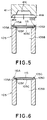
- Fig. 5 shows by way of sectional view the structure of another apparatus for securing a filter to a cylindrical member.
- a fusing die 41 is dimensioned to have a diameter appreciably larger than that of a cylindrical member 105 and includes in turn a taper part 41A having a tapered surface, a flat stepped part 41B and a recess 41c for allowing a filter to deform.
- a flat filter 115 is placed on an annular supporting part 105F raised above an annular receiving portion 105C, causing the flat filter 115 to be held in the slightly floated state.
- the fusing die 41 is lowered in the arrow-marked direction until the taper part 41A of the fusing die 41 comes in contact with the annular projected part 105D of the cylindrical member 105 so as to allow the latter to be squeezed with the taper part 41A.
- the annular projected part 105D is inwardly deformed by the tapered surface of the taper part 41A but a part of the filter 115 corresponding to the annular supporting part 105F of the cylindrical member 105 is depressed by the flat stepped part 41B of the fusing die 41, causing the central part of the filter 115 to be spherically or dome-shapedly expanded in the recess 41C of the fusing die 41.
- the annular projected part 105D is molten so that the peripheral part of the filter 115 is firmly covered with the molten resin of the annular projected part 105D as if it is enveloped in the latter.
- the annular supporting part 105F is simultaneously molten together with the annular projected part 105D of the cylindrical member 105 during the squeezing operation of the fusing die 41, it is ensured that ink leakage between the filter 115 and the cylindrical member 105 is prevented.
- Fig. 6 shows by way of sectional view a structure for securing a filter to a cylindrical member according to the present invention.
- This embodiment is different from that in each of the preceding embodiments described above with reference to Figs. 4 and 5 in respect of the structure of a cylindrical member 105 and the contour of an annular projected part 105D at the uppermost end 105A of the tubular member 105.
- an inclined surface 105G is formed outside of an annular projected part 105D.
- the contour of the annular projected part 105D proposed in this embodiment is employed, the inner wall surface 31A, 41A of the fusing head 31, 41 can effectively be brought in contact with the outer inclined surface 105G of the annular projected part 105D.
- the annular projected part 105D of the cylindrical member 105 is easily softened and molten, resulting in the filter 115 being reliably thermally secured to the cylindrical member 105.
- the present invention has been described above with respect to a recording head constructed according to each of preferred embodiments thereof wherein at least a part of the peripheral part 115A of the filter 115, preferably the whole peripheral part of the same is thermally fused to the foremost end part 105A of the cylindrical member 105A, it should of course be understood that the present invention should not be limited only to the case that a plurality of recording heads are integrally received in the head device 210 as shown in Figs. 1 and 2. Alternatively, the present invention may equally be applied to the case that a head device is composed of a single recording head and an ink tank to be fitted to the recording head.
- any type of material is employable as a raw material for the cylindrical member 105, provided that it is proven that it is molten when the heated fusing die comes in contact with the material, and moreover, it has no adverse effect on ink to be ejected from the recording head.
- immovable securing of the filter 115 to the cylindrical member 105 should not be limited to a heating process. Alternatively, a supersonic welding process may be employed for the same purpose.
- the form of an ink receiving member is selected to be cylindrical in considering sure and easy connectivity with a tank and also capability of supplying ink.
- the form of an ink receiving member may be any other from as long as the sure and easy connectivity and the capability of supplying ink would be satisfied.
- the present invention should not be limited only to the recording apparatus constructed in the form of a serial printer.
- the present invention may equally be applied to a line type printer wherein each recording operation is performed by activating a line type liquid eject recording head corresponding to the whole width of a recording sheet or a part of the same, a color printer, and a recording apparatus including a plurality of recording heads each ejecting ink having a single color or ink having a different concentration with the same advantageous effects as those of the serial printer.
- the present invention achieves distinct effect when applied to a recording head or a recording apparatus which has means for generating thermal energy such as electrothermal transducers or laser, and which causes changes in ink by the thermal energy so as to eject ink. This is because such a system can achieve a high density and high resolution recording.
- the present invention is advantageously employable for a serial type recording apparatus also in the case that a recording head fixedly secured to a main body of the recording apparatus or an exchangeable tip type recording head capable of making electrical connection to the main body of the recording apparatus or feeding ink from the main body of the recording apparatus is used for the recording apparatus.
- a recovery system or a preliminary auxiliary system for a recording head as a constituent of the recording apparatus because they serve to make the effect of the present invention more reliable.
- the recovery system are a capping means and a cleaning means for the recording head, and a pressure or suction means for the recording head.
- the preliminary auxiliary system are a preliminary heating means utilizing electrothermal transducers or a combination of other heater elements and the electrothermal transducers and a means for carrying out preliminary ejection of ink independently of the ejection for recording. These systems are effective for reliable recordings.
- the ink jet recording apparatus of the present invention can be employed not only as an image output terminal of an information processing device such as a computer, but also as an output device of a copying machine including a reader, and as an output device of a facsimile unit having a transmission and receiving function.
- the contour of a filter disposed on an ink supplying member of the liquid jet recording head should not be limited only to the semispherical shape as described above with reference to Figs. 4 to 6.
- the projected part of the filter may exhibit a substantially spherical shape rather than the semispherical shape, a conical shape, a frusto-conical shape, domy shape or a revolving parabolic shape.
- the ink supplying path may be constructed such that it serves as a filter as a whole, a reinforcement member for preventing the filter from being collapsed is disposed in the filter, the ink supplying path is caused to extend while it is increasingly expanded in the longitudinal direction, the ink supplying path is tapered toward the foremost end thereof corresponding to the shape of the filter so as to be connected to the latter, or a reinforcement member is disposed along the inner wall surface of the filter.
- a liquid receiving member (105) projected from the recording head comes in pressure contact with a porous member(120) filled in the ink tank(106).
- the periphery edge(115A) of a semispherically projected filter(115) is immovably embedded in the foremost end part(105A) of the cylindrical member(105) by employing a thermal fusing process.
Landscapes
- Engineering & Computer Science (AREA)
- Mechanical Engineering (AREA)
- Life Sciences & Earth Sciences (AREA)
- Wood Science & Technology (AREA)
- Chemical & Material Sciences (AREA)
- Composite Materials (AREA)
- Ink Jet (AREA)
Applications Claiming Priority (3)
| Application Number | Priority Date | Filing Date | Title |
|---|---|---|---|
| JP34567292 | 1992-12-25 | ||
| JP34567292 | 1992-12-25 | ||
| JP345672/92 | 1992-12-25 |
Publications (3)
| Publication Number | Publication Date |
|---|---|
| EP0603902A2 true EP0603902A2 (de) | 1994-06-29 |
| EP0603902A3 EP0603902A3 (de) | 1995-02-22 |
| EP0603902B1 EP0603902B1 (de) | 2000-05-24 |
Family
ID=18378187
Family Applications (1)
| Application Number | Title | Priority Date | Filing Date |
|---|---|---|---|
| EP93120835A Expired - Lifetime EP0603902B1 (de) | 1992-12-25 | 1993-12-23 | Flüssigkeitstrahlkopf und Vorrichtung dafür |
Country Status (3)
| Country | Link |
|---|---|
| US (1) | US5900898A (de) |
| EP (1) | EP0603902B1 (de) |
| DE (1) | DE69328714T2 (de) |
Cited By (3)
| Publication number | Priority date | Publication date | Assignee | Title |
|---|---|---|---|---|
| EP0657291A1 (de) * | 1993-12-07 | 1995-06-14 | Lexmark International, Inc. | Tintenstrahlkartusche |
| EP0931658A1 (de) | 1998-01-23 | 1999-07-28 | Océ-Technologies B.V. | Tintenstrahlvorrichtung mit Filterelement |
| US6152560A (en) * | 1998-01-23 | 2000-11-28 | Oce-Technologies B.V. | Ink jet device with a filter element |
Families Citing this family (23)
| Publication number | Priority date | Publication date | Assignee | Title |
|---|---|---|---|---|
| JP3278410B2 (ja) | 1998-05-11 | 2002-04-30 | キヤノン株式会社 | 液体収納容器、該容器の製造方法、該容器のパッケージ、該容器と記録ヘッドとを一体化したインクジェットヘッドカートリッジ及び液体吐出記録装置 |
| US6340216B1 (en) * | 1998-09-30 | 2002-01-22 | Xerox Corporation | Ballistic aerosol marking apparatus for treating a substrate |
| US6467862B1 (en) | 1998-09-30 | 2002-10-22 | Xerox Corporation | Cartridge for use in a ballistic aerosol marking apparatus |
| US6523928B2 (en) | 1998-09-30 | 2003-02-25 | Xerox Corporation | Method of treating a substrate employing a ballistic aerosol marking apparatus |
| US6291088B1 (en) | 1998-09-30 | 2001-09-18 | Xerox Corporation | Inorganic overcoat for particulate transport electrode grid |
| US6454384B1 (en) | 1998-09-30 | 2002-09-24 | Xerox Corporation | Method for marking with a liquid material using a ballistic aerosol marking apparatus |
| US6328409B1 (en) | 1998-09-30 | 2001-12-11 | Xerox Corporation | Ballistic aerosol making apparatus for marking with a liquid material |
| US6416157B1 (en) | 1998-09-30 | 2002-07-09 | Xerox Corporation | Method of marking a substrate employing a ballistic aerosol marking apparatus |
| US6416156B1 (en) | 1998-09-30 | 2002-07-09 | Xerox Corporation | Kinetic fusing of a marking material |
| US6751865B1 (en) | 1998-09-30 | 2004-06-22 | Xerox Corporation | Method of making a print head for use in a ballistic aerosol marking apparatus |
| US6265050B1 (en) | 1998-09-30 | 2001-07-24 | Xerox Corporation | Organic overcoat for electrode grid |
| US6511149B1 (en) | 1998-09-30 | 2003-01-28 | Xerox Corporation | Ballistic aerosol marking apparatus for marking a substrate |
| US6290342B1 (en) | 1998-09-30 | 2001-09-18 | Xerox Corporation | Particulate marking material transport apparatus utilizing traveling electrostatic waves |
| US6328436B1 (en) | 1999-09-30 | 2001-12-11 | Xerox Corporation | Electro-static particulate source, circulation, and valving system for ballistic aerosol marking |
| US6293659B1 (en) | 1999-09-30 | 2001-09-25 | Xerox Corporation | Particulate source, circulation, and valving system for ballistic aerosol marking |
| JP2002137410A (ja) | 2000-11-02 | 2002-05-14 | Canon Inc | 液体吐出記録ヘッド |
| US6513920B1 (en) * | 2001-08-13 | 2003-02-04 | Hewlett-Packard Company | Controlling diffused-air bubbles in ink-jet print cartridges |
| US6998008B2 (en) * | 2003-07-15 | 2006-02-14 | Lexmark International, Inc. | Method and apparatus for attaching an ink jet filter to an ink cartridge |
| US6969160B2 (en) * | 2003-07-28 | 2005-11-29 | Xerox Corporation | Ballistic aerosol marking apparatus |
| US8066363B2 (en) * | 2005-03-31 | 2011-11-29 | Lexmark International, Inc. | Printhead filter systems and methods for manufacturing the same |
| EP2346697B1 (de) * | 2008-10-30 | 2012-08-01 | Hewlett-Packard Development Company, L.P. | Fluidverbindung für fluidausstosssystem |
| JP5618052B2 (ja) * | 2010-03-19 | 2014-11-05 | セイコーエプソン株式会社 | 液体噴射ヘッド及び液体噴射装置 |
| JP6149526B2 (ja) * | 2012-08-08 | 2017-06-21 | セイコーエプソン株式会社 | 液体収容容器および液体供給システム |
Family Cites Families (74)
| Publication number | Priority date | Publication date | Assignee | Title |
|---|---|---|---|---|
| BE538818A (de) * | 1954-07-19 | 1900-01-01 | ||
| US3708118A (en) * | 1971-04-19 | 1973-01-02 | Dick Co Ab | Filtering apparatus for a drop writing system |
| US3779390A (en) * | 1972-05-18 | 1973-12-18 | Itt | Filter assembly |
| US4014797A (en) * | 1973-12-11 | 1977-03-29 | Burron Medical Products, Inc. | Intravenous injection apparatus and needle adapter with filter and method of making same |
| CA1127227A (en) * | 1977-10-03 | 1982-07-06 | Ichiro Endo | Liquid jet recording process and apparatus therefor |
| JPS5936879B2 (ja) * | 1977-10-14 | 1984-09-06 | キヤノン株式会社 | 熱転写記録用媒体 |
| JPS5830825B2 (ja) * | 1978-06-26 | 1983-07-01 | 株式会社リコー | インクジェット用インク供給装置 |
| US4330787A (en) * | 1978-10-31 | 1982-05-18 | Canon Kabushiki Kaisha | Liquid jet recording device |
| US4345262A (en) * | 1979-02-19 | 1982-08-17 | Canon Kabushiki Kaisha | Ink jet recording method |
| US4463359A (en) * | 1979-04-02 | 1984-07-31 | Canon Kabushiki Kaisha | Droplet generating method and apparatus thereof |
| US4313124A (en) * | 1979-05-18 | 1982-01-26 | Canon Kabushiki Kaisha | Liquid jet recording process and liquid jet recording head |
| JPS5667269A (en) * | 1979-11-06 | 1981-06-06 | Seiko Epson Corp | Ink tank |
| JPS5716385A (en) * | 1980-07-04 | 1982-01-27 | Hitachi Ltd | Nuclear fusion apparatus |
| JPS57116680A (en) * | 1981-01-13 | 1982-07-20 | Canon Inc | Ink feeder |
| US4558333A (en) * | 1981-07-09 | 1985-12-10 | Canon Kabushiki Kaisha | Liquid jet recording head |
| JPS58181656A (ja) * | 1982-04-19 | 1983-10-24 | Ricoh Co Ltd | インクジエツトプリンタ− |
| JPS5919168A (ja) * | 1982-07-26 | 1984-01-31 | Canon Inc | インクジエツト記録ヘツド |
| JPS5933154A (ja) * | 1982-08-19 | 1984-02-22 | Canon Inc | インクジエツト記録装置 |
| US4509062A (en) * | 1982-11-23 | 1985-04-02 | Hewlett-Packard Company | Ink reservoir with essentially constant negative back pressure |
| JPS59123670A (ja) * | 1982-12-28 | 1984-07-17 | Canon Inc | インクジエツトヘツド |
| JPS59138461A (ja) * | 1983-01-28 | 1984-08-08 | Canon Inc | 液体噴射記録装置 |
| US4635078A (en) * | 1983-04-28 | 1987-01-06 | Canon Kabushiki Kaisha | Intermediate gradient image producing method |
| JPS6071260A (ja) * | 1983-09-28 | 1985-04-23 | Erumu:Kk | 記録装置 |
| JPS6085962A (ja) * | 1983-10-17 | 1985-05-15 | Ricoh Co Ltd | インクカセツトにおけるインク封止構造 |
| JPH0643129B2 (ja) * | 1984-03-01 | 1994-06-08 | キヤノン株式会社 | インクジェット記録ヘッド |
| US4635080A (en) * | 1984-03-30 | 1987-01-06 | Canon Kabushiki Kaisha | Liquid injection recording apparatus |
| JPS60206657A (ja) * | 1984-03-31 | 1985-10-18 | Canon Inc | 液体噴射記録ヘツド |
| JPS60232965A (ja) * | 1984-05-07 | 1985-11-19 | Ricoh Co Ltd | 圧電フイルムポンプ |
| JPS60234848A (ja) * | 1984-05-08 | 1985-11-21 | Canon Inc | 液体噴射記録ヘツド |
| JPS6135958A (ja) * | 1984-07-28 | 1986-02-20 | Konishiroku Photo Ind Co Ltd | インク供給コネクタ |
| US4571599A (en) * | 1984-12-03 | 1986-02-18 | Xerox Corporation | Ink cartridge for an ink jet printer |
| JPH0729416B2 (ja) * | 1985-12-27 | 1995-04-05 | キヤノン株式会社 | 液体噴射記録ヘツド |
| JPS62208947A (ja) * | 1986-03-11 | 1987-09-14 | Seiko Epson Corp | インクジエツト記録装置用ヘツド |
| US4706097A (en) * | 1986-04-03 | 1987-11-10 | Hewlett Packard Company | Near-linear spring connect structure for flexible interconnect circuits |
| US5025271A (en) * | 1986-07-01 | 1991-06-18 | Hewlett-Packard Company | Thin film resistor type thermal ink pen using a form storage ink supply |
| US4771295B1 (en) * | 1986-07-01 | 1995-08-01 | Hewlett Packard Co | Thermal ink jet pen body construction having improved ink storage and feed capability |
| JPS6337954A (ja) * | 1986-08-01 | 1988-02-18 | Canon Inc | 液体噴射記録装置 |
| JP2681350B2 (ja) * | 1986-11-19 | 1997-11-26 | キヤノン株式会社 | インクジェット装置 |
| JP2563784B2 (ja) * | 1986-12-18 | 1996-12-18 | セイコーエプソン株式会社 | インクジェット記録装置におけるインク供給用チューブの接続構造 |
| US4774529A (en) * | 1987-02-26 | 1988-09-27 | Xerox Corporation | Repositionable marking head for increasing printing speed |
| US4907018A (en) * | 1988-11-21 | 1990-03-06 | Hewlett-Packard Company | Printhead-carriage alignment and electrical interconnect lock-in mechanism |
| CA1304983C (en) * | 1987-10-23 | 1992-07-14 | David W. Pinkernell | Printhead-carriage alignment and electrical interconnect lock-in mechanism |
| US4920362A (en) * | 1988-12-16 | 1990-04-24 | Hewlett-Packard Company | Volumetrically efficient ink jet pen capable of extreme altitude and temperature excursions |
| JPH01133747A (ja) * | 1987-11-20 | 1989-05-25 | Canon Inc | 液体噴射記録ヘッド |
| US4794409A (en) * | 1987-12-03 | 1988-12-27 | Hewlett-Packard Company | Ink jet pen having improved ink storage and distribution capabilities |
| US5182581A (en) * | 1988-07-26 | 1993-01-26 | Canon Kabushiki Kaisha | Ink jet recording unit having an ink tank section containing porous material and a recording head section |
| JPH0782399B2 (ja) * | 1988-07-28 | 1995-09-06 | 科学技術庁無機材質研究所長 | 合成用高圧高温装置の発生温度の検知ならびに合成温度制御法 |
| EP0361034A3 (de) * | 1988-09-28 | 1990-07-11 | Siemens Aktiengesellschaft | Tintenschreibkopf |
| ES2076217T3 (es) * | 1988-10-31 | 1995-11-01 | Canon Kk | Aparato para la impresion por chorros de liquido. |
| US4994824A (en) * | 1988-12-16 | 1991-02-19 | Hewlett-Packard Company | Modal ink jet printing system |
| US5103243A (en) * | 1988-12-16 | 1992-04-07 | Hewlett-Packard Company | Volumetrically efficient ink jet pen capable of extreme altitude and temperature excursions |
| JP2575205B2 (ja) * | 1989-01-13 | 1997-01-22 | キヤノン株式会社 | インクタンク |
| JP2845916B2 (ja) * | 1989-01-13 | 1999-01-13 | キヤノン株式会社 | 液体収納容器,液体噴射記録ヘッドおよび液体吐出記録装置 |
| JP2622178B2 (ja) * | 1989-01-17 | 1997-06-18 | キヤノン株式会社 | インクジェットカートリッジ及び該カートリッジを用いたインクジェット記録装置 |
| JPH02198881A (ja) * | 1989-01-27 | 1990-08-07 | Shimadzu Corp | プリンタ |
| US5162817A (en) * | 1989-01-28 | 1992-11-10 | Canon Kabushiki Kaisha | Ink jet with residual ink detection that compensates for different ink properties |
| JPH02204044A (ja) * | 1989-02-03 | 1990-08-14 | Canon Inc | インクジェットヘッド |
| CA2009631C (en) * | 1989-02-17 | 1994-09-20 | Shigeo Nonoyama | Pressure damper of an ink jet printer |
| US4967207A (en) * | 1989-07-26 | 1990-10-30 | Hewlett-Packard Company | Ink jet printer with self-regulating refilling system |
| EP0578331B1 (de) * | 1989-09-18 | 1997-12-29 | Canon Kabushiki Kaisha | Methode zum Füllen einer Tintenpatrone für Tintenstrahlaufzeichnungsgeräte |
| US4994828A (en) * | 1989-11-14 | 1991-02-19 | Eastman Kodak Company | Camera apparatus for preventing load of exposed film |
| JPH03169557A (ja) * | 1989-11-29 | 1991-07-23 | Seiko Epson Corp | インクジェットヘッド |
| EP0444654B1 (de) * | 1990-02-28 | 1997-07-23 | Canon Kabushiki Kaisha | Tintenstrahlgerät |
| JP2801353B2 (ja) * | 1990-04-11 | 1998-09-21 | キヤノン株式会社 | インクジェットカートリッジ及び該インクジェットカートリッジを備えたインクジェット記録装置 |
| US5221334A (en) * | 1990-04-11 | 1993-06-22 | E. I. Du Pont De Nemours And Company | Aqueous pigmented inks for ink jet printers |
| JP2880334B2 (ja) * | 1990-10-03 | 1999-04-05 | キヤノン株式会社 | インクジェット記録装置用記録ヘッドユニットおよびインクジェット記録装置 |
| US5444473A (en) * | 1990-11-15 | 1995-08-22 | Canon Kabushiki Kaisha | Ink jet recording apparatus |
| JPH04206752A (ja) * | 1990-11-30 | 1992-07-28 | Mitsubishi Electric Corp | 面実装形icの検査装置 |
| DE69118489T2 (de) * | 1990-11-30 | 1996-08-14 | Canon Kk | Tintenbehälter und Aufzeichnungskopf mit einem solchen Behälter |
| JPH04214362A (ja) * | 1990-12-10 | 1992-08-05 | Canon Inc | インクジェット記録装置,インクタンク,および記録ヘッドとインクタンクとを一体としたヘッドカートリッジ |
| US5233369A (en) * | 1990-12-27 | 1993-08-03 | Xerox Corporation | Method and apparatus for supplying ink to an ink jet printer |
| US5430471A (en) * | 1991-08-30 | 1995-07-04 | Canon Kabushiki Kaisha | Liquid container, recording head using same and recording apparatus using same |
| US5262808A (en) * | 1991-12-05 | 1993-11-16 | Polaroid Corporation | Camera, accessories and method of taking photographs |
| JP3148005B2 (ja) * | 1992-06-16 | 2001-03-19 | キヤノン株式会社 | 記録カートリッジおよびインクジェット記録装置 |
-
1993
- 1993-12-23 EP EP93120835A patent/EP0603902B1/de not_active Expired - Lifetime
- 1993-12-23 DE DE69328714T patent/DE69328714T2/de not_active Expired - Lifetime
-
1996
- 1996-11-12 US US08/747,748 patent/US5900898A/en not_active Expired - Lifetime
Cited By (4)
| Publication number | Priority date | Publication date | Assignee | Title |
|---|---|---|---|---|
| EP0657291A1 (de) * | 1993-12-07 | 1995-06-14 | Lexmark International, Inc. | Tintenstrahlkartusche |
| US5537136A (en) * | 1993-12-07 | 1996-07-16 | Lexmark International, Inc. | Ink jet cartridge including filter inserts |
| EP0931658A1 (de) | 1998-01-23 | 1999-07-28 | Océ-Technologies B.V. | Tintenstrahlvorrichtung mit Filterelement |
| US6152560A (en) * | 1998-01-23 | 2000-11-28 | Oce-Technologies B.V. | Ink jet device with a filter element |
Also Published As
| Publication number | Publication date |
|---|---|
| EP0603902B1 (de) | 2000-05-24 |
| US5900898A (en) | 1999-05-04 |
| DE69328714D1 (de) | 2000-06-29 |
| EP0603902A3 (de) | 1995-02-22 |
| DE69328714T2 (de) | 2000-12-28 |
Similar Documents
| Publication | Publication Date | Title |
|---|---|---|
| US5900898A (en) | Liquid jet head having a contoured and secured filter, liquid jet apparatus using same, and method of immovably securing a filter to a liquid receiving member of a liquid jet head | |
| JP2831804B2 (ja) | インクジェット記録装置の回復方法 | |
| US8152267B2 (en) | Ink jet recording apparatus | |
| JP3171753B2 (ja) | インクジェット記録装置 | |
| JP2000141633A (ja) | キャリアの記録手段着脱機構及び該機構を用いたインクジェット記録装置 | |
| US5940102A (en) | Ink jet cartridge, ink jet apparatus and ink container | |
| JP3352198B2 (ja) | 液体噴射ヘッドおよび該液体噴射ヘッド使用の液体噴射装置 | |
| JPH10157153A (ja) | インクジェット記録装置 | |
| JPH036170A (ja) | 画像通信装置 | |
| JP2001113797A (ja) | 画像形成装置 | |
| US6082847A (en) | Image system with informing means | |
| JPH10114084A (ja) | 画像形成装置およびこれに用いるプリントヘッド | |
| JP3235735B2 (ja) | インクジェット記録ヘッドおよびこれを搭載した記録装置 | |
| JP3238756B2 (ja) | インクジェットカートリッジおよび記録装置 | |
| JP3236476B2 (ja) | 廃インクタンク | |
| JPH06143548A (ja) | インクジェット記録装置 | |
| JP2001080090A (ja) | 画像記録装置及びカートリッジ | |
| JP3347680B2 (ja) | 記録装置 | |
| JP4266263B2 (ja) | インクジェット記録装置及び画像形成装置 | |
| JP3184629B2 (ja) | インクジェット記録装置 | |
| US6056393A (en) | Ink-jet recording head and ink-jet cartridge | |
| JP3445036B2 (ja) | 画像記録装置 | |
| JPH0615832A (ja) | インクジェット記録装置 | |
| JPH05325729A (ja) | 記録装置 | |
| JPH07205419A (ja) | インクジェット装置 |
Legal Events
| Date | Code | Title | Description |
|---|---|---|---|
| PUAI | Public reference made under article 153(3) epc to a published international application that has entered the european phase |
Free format text: ORIGINAL CODE: 0009012 |
|
| AK | Designated contracting states |
Kind code of ref document: A2 Designated state(s): DE FR GB IT |
|
| PUAL | Search report despatched |
Free format text: ORIGINAL CODE: 0009013 |
|
| AK | Designated contracting states |
Kind code of ref document: A3 Designated state(s): DE FR GB IT |
|
| 17P | Request for examination filed |
Effective date: 19950710 |
|
| 17Q | First examination report despatched |
Effective date: 19960620 |
|
| GRAG | Despatch of communication of intention to grant |
Free format text: ORIGINAL CODE: EPIDOS AGRA |
|
| GRAG | Despatch of communication of intention to grant |
Free format text: ORIGINAL CODE: EPIDOS AGRA |
|
| GRAH | Despatch of communication of intention to grant a patent |
Free format text: ORIGINAL CODE: EPIDOS IGRA |
|
| GRAH | Despatch of communication of intention to grant a patent |
Free format text: ORIGINAL CODE: EPIDOS IGRA |
|
| GRAA | (expected) grant |
Free format text: ORIGINAL CODE: 0009210 |
|
| AK | Designated contracting states |
Kind code of ref document: B1 Designated state(s): DE FR GB IT |
|
| REF | Corresponds to: |
Ref document number: 69328714 Country of ref document: DE Date of ref document: 20000629 |
|
| ITF | It: translation for a ep patent filed | ||
| ET | Fr: translation filed | ||
| PLBE | No opposition filed within time limit |
Free format text: ORIGINAL CODE: 0009261 |
|
| STAA | Information on the status of an ep patent application or granted ep patent |
Free format text: STATUS: NO OPPOSITION FILED WITHIN TIME LIMIT |
|
| 26N | No opposition filed | ||
| REG | Reference to a national code |
Ref country code: GB Ref legal event code: IF02 |
|
| PGFP | Annual fee paid to national office [announced via postgrant information from national office to epo] |
Ref country code: IT Payment date: 20101217 Year of fee payment: 18 Ref country code: GB Payment date: 20101223 Year of fee payment: 18 |
|
| PGFP | Annual fee paid to national office [announced via postgrant information from national office to epo] |
Ref country code: DE Payment date: 20101231 Year of fee payment: 18 |
|
| PGFP | Annual fee paid to national office [announced via postgrant information from national office to epo] |
Ref country code: FR Payment date: 20120103 Year of fee payment: 19 |
|
| GBPC | Gb: european patent ceased through non-payment of renewal fee |
Effective date: 20121223 |
|
| REG | Reference to a national code |
Ref country code: FR Ref legal event code: ST Effective date: 20130830 |
|
| REG | Reference to a national code |
Ref country code: DE Ref legal event code: R119 Ref document number: 69328714 Country of ref document: DE Effective date: 20130702 |
|
| PG25 | Lapsed in a contracting state [announced via postgrant information from national office to epo] |
Ref country code: DE Free format text: LAPSE BECAUSE OF NON-PAYMENT OF DUE FEES Effective date: 20130702 |
|
| PG25 | Lapsed in a contracting state [announced via postgrant information from national office to epo] |
Ref country code: GB Free format text: LAPSE BECAUSE OF NON-PAYMENT OF DUE FEES Effective date: 20121223 Ref country code: FR Free format text: LAPSE BECAUSE OF NON-PAYMENT OF DUE FEES Effective date: 20130102 |
|
| PG25 | Lapsed in a contracting state [announced via postgrant information from national office to epo] |
Ref country code: IT Free format text: LAPSE BECAUSE OF NON-PAYMENT OF DUE FEES Effective date: 20121223 |