EP0603982B1 - Fadenschneider - Google Patents
Fadenschneider Download PDFInfo
- Publication number
- EP0603982B1 EP0603982B1 EP19930203656 EP93203656A EP0603982B1 EP 0603982 B1 EP0603982 B1 EP 0603982B1 EP 19930203656 EP19930203656 EP 19930203656 EP 93203656 A EP93203656 A EP 93203656A EP 0603982 B1 EP0603982 B1 EP 0603982B1
- Authority
- EP
- European Patent Office
- Prior art keywords
- housing
- motor shaft
- support
- wheel
- motor
- Prior art date
- Legal status (The legal status is an assumption and is not a legal conclusion. Google has not performed a legal analysis and makes no representation as to the accuracy of the status listed.)
- Expired - Lifetime
Links
Images


Classifications
-
- A—HUMAN NECESSITIES
- A01—AGRICULTURE; FORESTRY; ANIMAL HUSBANDRY; HUNTING; TRAPPING; FISHING
- A01D—HARVESTING; MOWING
- A01D34/00—Mowers; Mowing apparatus of harvesters
- A01D34/835—Mowers; Mowing apparatus of harvesters specially adapted for particular purposes
- A01D34/84—Mowers; Mowing apparatus of harvesters specially adapted for particular purposes for edges of lawns or fields, e.g. for mowing close to trees or walls
-
- A—HUMAN NECESSITIES
- A01—AGRICULTURE; FORESTRY; ANIMAL HUSBANDRY; HUNTING; TRAPPING; FISHING
- A01D—HARVESTING; MOWING
- A01D34/00—Mowers; Mowing apparatus of harvesters
- A01D34/835—Mowers; Mowing apparatus of harvesters specially adapted for particular purposes
- A01D34/90—Mowers; Mowing apparatus of harvesters specially adapted for particular purposes for carrying by the operator
Definitions
- the invention relates to a device for trimming vegetation, such as grass and the like, comprising a motor housing, a motor with motor shaft mounted therein and a reel carried by the shaft for at least one line, the or each end part of which is unwound and cut off over a pre-determined length and rotated round the motor shaft in an active plane perpendicular to the motor shaft, as well as a handle connected to the housing and wherein a cover plate connected to the housing is arranged on the same side of the housing as the handle, said cover plate extending above the active plane.
- Such devices can be used in two main positions, namely that wherein the end of the line is swung around in a practically horizontal plane and that wherein the end of the line is swung around in a practically vertical plane.
- the handle For easy handling of the device the handle must therefore be adjusted relative to the housing and the support of the device on the ground must likewise be adapted.
- the invention has for its object to improve the support such that not only is a good guiding realized in the vertical plane, but that the guiding in the horizontal plane also serves to prevent wire breakage and excessive wear of the line.
- the device according to the invention is distinguished in that a bounding element defining a curved outer periphery is arranged on the side of the housing remote from the handle and inbetween said cover plate and said plane and extending, as seen in the axial direction of the motor shaft, not further than the circle covered by the line, the bounding element being one or more wheels.
- This support may have a relatively large radius of curvature resulting in the advantage of vertical movements which are relatively small and a horizontal movement which remains rectilinear, also on uneven grass or ground surfaces.
- the bounding element moreover extends over a large part of the active plane of the line end portion, the line will not be bent close to the wire reel when approaching an obstacle but at a greater distance which considerably reduces the danger of wire breakage.
- housing 1 On the underside of housing 1 a motor shaft 3 protrudes downward, on which motor shaft is arranged a reel 4 for a trimming line 5.
- the trimming line 5 is wound onto the reel and protected in a reel housing 6, which housing is provided with a passage opening 7 for guiding through the active end part of line 5.
- Housing 6 is closed off on the underside by a press-in cover 9 which can support on the ground. By pressing in a cover 9, a determined length of line 5 is released each time and cut to length in order to enable cutting of the grass.
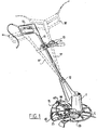
- the housing 1 is further provided with a handle 10 which is embodied with a shank 11 which is connected to a part of the housing 1 via a ball joint 12.
- a second handle 13 can be arranged halfway along the shank.
- the shank and handle 10, 11 can be set in various ways, which is further elucidated below.
- cover plate 15 On the side of housing 1 lying towards the handle 10 the active plane through which the line 5 is moved is protected on the top side by a cover plate 15.
- This cover plate serves as protection against grass, small stones, sand or wire portions being thrown around which can be dangerous for the user and his surroundings.
- the cover plate 15 only covers a sector angle of the complete circle around the bottom end of the housing, so that the wire remains fully visible on the side of the housing 1 remote from the user. This serves for observation of the work.
- the wire end part 5 can come too close to obstacles, as indicated in figure 3a by a wall M.
- the invention proposes arrangement of a bounding element 20.
- the bounding element 20 is embodied as a spoke wheel mounted concentrically round the motor shaft 3 on the underside of housing 1.
- Figure 2 shows that the spoke wheel can be slightly cup-shaped in order to place the peripheral edge 21 close to the active plane of the wire end 5.
- the bounding wheel 20 is freely rotatable so that, see figure 3a, housing 1 respectively reel housing 6 cannot come too close to the wall M.
- the wire end part 5 is therefore bent through a wider angle whereby wire breakage is avoided.
- the bounding element 20 is used as roller wheel, wherein the periphery 21, whether or not provided with a profile, rolls over the ground surface B. Due to the comparatively large wheel periphery, that is, the relatively large radius of curvature, operation of the device in this position is also considerably facilitated as support.
- the device In the position according to figure 3a, the device is supported by a carriage 25 on the underside of the cover plate 15.
- a special feature of this carriage 25 is that it extends from the edge of the cover plate in the direction of the rotation shaft 3 of the reel 4. The carriage 25 therefore leaves clear the cover 9 of reel housing 6 such that this remains freely accessible for replacing the reel and for regularly being able to supply new lengths of wire 5.
- FIG 4 an alternative embodiment of a carriage.
- This carriage consists of a supporting surface 26 which extends under reel 4 respectively reel housing 6 and which in the embodiment shown has a forked shape, consisting here of four parallel wire ends 27 which are mutually connected on the front side and continue in a wire 28, the end of which is mounted in two eyelets 29 on the front side of motor housing 1.
- the wire 28 is freely turnable in the eyelets 29 so that when the wire swivels to the left or right the wire ends 27 adjacent the reel housing 6 turn, whereby this left clear.
- This special support according to figure 4 can thus also swivel away when the device is used in the position according to figure 3b, that is, that bounding element 20 and the shape of the wheel can roll freely over the ground.
- the support of the device will however remain optimal when the device is moved forward by means of the handle 10 (not shown in figure 4), wherein the wire ends 27 exert a self-aligning action on the support owing to the eccentric mounting 29 of the support.
- the wire 28 of the support is curved such that it remains out of the active plane of the line 5.
- the support wire 28 can also be pushed and fixed into eyelets 29 in axial direction so that a height adjustment is easily realized.
- Figure 5 shows an alternative embodiment wherein the plate 15 at the rear is extended toward the front at 30, along the periphery of which a number of free-turning wheels 31 are mounted.
- the circle covered along the outside of wheels 31 forms a support surface that is movable relative to housing 1, so that a sufficient bounding is also obtained here to safeguard the line end 5, while the device can easily be moved forward over the field when it is used in the position according to figure 3b.
- Figure 6 shows a development of the embodiment accord- ing to figure 5 wherein the wheels 31' are suitable for guiding a belt 32 which is trained therearound.
- the belt serves for a uniform support of the device in the position according to figure 3b.
- Figure 7 shows a detail of the bounding element 20, on the periphery of which is arranged a cutting member 60 in the form of a cutting blade.
- the cutting edge 61 is oriented such that, in the rotation direction of the wire 5, the end 5' thereof is cut off in order to bring wire 5 to the correct length relative to the axis of rotation.
- the cutting blade 60 can be pivoted relative to the spoke 62 of the wheel 20, on which two arms 64 of blade 60 are rotatable round 63.
- the knife blade 60 can thus be folded away from the position drawn with full lines in figure 7 to a position drawn with dashed lines so that the wire 5 can move through beneath knife blade 60.
- Shorter and longer wire ends can be realized by fixing knife-like cutting blades in other manner to for instance motor housing 1 respectively plate 15.
- FIG. 1 Shown for example in figure 1 is a knife blade 60 which is arranged on a bent arm 65 which is mounted in plate 15 for rotation at 66.
- a handle 67 is provided at the top end with which it is possible to turn knife blade 60 round the passage opening 66 and to thus place it under or outside the wheel-shaped bounding element 20.
- the wire can thereby be cut off shorter than the periphery of the wheel or longer than the periphery of the wheel or any intermediate length.
- a knife blade 60 is arranged on a pin 68 which is supported on the housing by eyelet-like supports 69.
- the pin 68, and thus the knife 60 can be moved up and downward by means of the knob 70 such that the knife can be carried from a position above wheel 20 to below wheel 20.
- the wire 5 can hereby be cut of if at a desired short length.
- a reset spring 71 which acts on the pin 68 provides an automatic return of knife blade 60 above the wheel 20.
Landscapes
- Life Sciences & Earth Sciences (AREA)
- Environmental Sciences (AREA)
- Harvester Elements (AREA)
Claims (14)
- Vorrichtung zum Beschneiden von Pflanzenwuchs, wie Gras und dergleichen, mit einem Motorgehäuse (1), einem darin eingebauten Motor (2) mit einer Motorwelle (3) und einer durch die Welle gehaltenen Spule (4) für wenigstens eine(n) Schnur bzw. Draht, wobei das oder jedes Ende der Schnur abgewickelt und auf eine vorbestimmte Länge abgeschnitten ist und um die Motorwelle in einer Wirkebene senkrecht zu der Motorwelle gedreht wird, sowie einem mit dem Gehäuse verbundenen Handgriff (10), wobei eine mit dem Gehäuse verbundene Abdeckplatte (15) an der gleichen Seite des Gehäuses wie der Handgriff angeordnet ist und sich die Abdeckplatte (15) oberhalb der Wirkebene erstreckt,
dadurch gekennzeichnet,
daß ein Randelement, welches einen gekrümmten Außenumfang definiert, an der dem Handgriff abgewandten Seite des Gehäuses und zwischen der Abdeckplatte und der Ebene angeordnet ist und sich, in der Axialrichtung der Motorwelle betrachtet, nicht weiter als der durch die Schnur abgedeckte Kreis erstreckt, wobei das Randelement durch ein oder mehrere Räder (20, 31) gebildet ist. - Vorrichtung nach Anspruch 1,
dadurch gekennzeichnet,
daß das eine Rad (20) drehbar konzentrisch um die Motorwelle (3) befestigt ist. - Vorrichtung nach Anspruch 2,
dadurch gekennzeichnet,
daß das eine Rad mit Speichen versehen ist. - Vorrichtung nach Anspruch 1, wobei die Abdeckplatte (15) mehrere Räder (31) trägt,
dadurch gekennzeichnet,
daß ein elastisches Element, wie ein Riemen (32), um die Räder (31) gezogen ist. - Vorrichtung nach Anspruch 1 oder 4,
dadurch gekennzeichnet,
daß das oder die Räder (20, 31) angetrieben sind. - Vorrichtung nach einem der vorangehenden Ansprüche,
dadurch gekennzeichnet,
daß mit dem Gehäuse verbunden eine Abstützung (25) angeordnet ist, die sich außerhalb der Wirkebene des Schnurendes zu einer Position nahe der Drehachse (3) der Schnurspule (4) erstreckt. - Vorrichtung nach Anspruch 6,
dadurch gekennzeichnet,
daß die Schlittenabstützung (25) ein Teil (28) aufweist, das bezüglich des Motorgehäuses (1) schwenkbar angeordnet ist. - Vorrichtung nach Anspruch 7,
dadurch gekennzeichnet,
daß die Abstützung höhenverstellbar, d.h. in Richtung zum Motor hin und vom Motor weg verstellbar ist. - Vorrichtung nach Anspruch 7 oder 8,
dadurch gekennzeichnet,
daß die Abstützung lösbar (29) mit dem Gehäuse verbunden ist. - Vorrichtung nach einem der Ansprüche 7 bis 9,
dadurch gekennzeichnet,
daß die Schwenkachse (29) der Schlittenabstützung (25) parallel zu der Motorwelle (3) und in einem Abstand von dieser verläuft. - Vorrichtung nach einem der Ansprüche 7 bis 10,
dadurch gekennzeichnet,
daß die Schlittenabstützung ein gabelförmiges Ende (27) aufweist. - Vorrichtung nach einem der vorangehenden Ansprüche,
dadurch gekennzeichnet,
daß ein Schneidelement (60) in dem Raum unter dem als Rad (20) verkörperten Randelement angeordnet sein kann. - Vorrichtung nach Anspruch 12,
dadurch gekennzeichnet,
daß das Schneidelement (60) auf unterschiedliche Abstände bezüglich der Motorwelle eingestellt sein kann. - Vorrichtung nach Anspruch 12 oder 13,
dadurch gekennzeichnet,
daß das Schneidelement auf dem als Rad verkörperten Randelement angeordnet ist.
Priority Applications (1)
| Application Number | Priority Date | Filing Date | Title |
|---|---|---|---|
| EP99204032A EP0976313A3 (de) | 1992-12-23 | 1993-12-23 | Fadenschneider |
Applications Claiming Priority (4)
| Application Number | Priority Date | Filing Date | Title |
|---|---|---|---|
| NL9202252A NL9202252A (nl) | 1992-12-23 | 1992-12-23 | Inrichting voor het trimmen van gewas. |
| NL9202252 | 1992-12-23 | ||
| NL9301416 | 1993-08-16 | ||
| NL9301416A NL9301416A (nl) | 1992-12-23 | 1993-08-16 | Inrichting voor het trimmen van gewas. |
Related Child Applications (1)
| Application Number | Title | Priority Date | Filing Date |
|---|---|---|---|
| EP99204032A Division EP0976313A3 (de) | 1992-12-23 | 1993-12-23 | Fadenschneider |
Publications (3)
| Publication Number | Publication Date |
|---|---|
| EP0603982A2 EP0603982A2 (de) | 1994-06-29 |
| EP0603982A3 EP0603982A3 (de) | 1994-10-19 |
| EP0603982B1 true EP0603982B1 (de) | 2000-08-23 |
Family
ID=26647040
Family Applications (2)
| Application Number | Title | Priority Date | Filing Date |
|---|---|---|---|
| EP19930203656 Expired - Lifetime EP0603982B1 (de) | 1992-12-23 | 1993-12-23 | Fadenschneider |
| EP99204032A Withdrawn EP0976313A3 (de) | 1992-12-23 | 1993-12-23 | Fadenschneider |
Family Applications After (1)
| Application Number | Title | Priority Date | Filing Date |
|---|---|---|---|
| EP99204032A Withdrawn EP0976313A3 (de) | 1992-12-23 | 1993-12-23 | Fadenschneider |
Country Status (3)
| Country | Link |
|---|---|
| EP (2) | EP0603982B1 (de) |
| DE (1) | DE69329270T2 (de) |
| NL (1) | NL9301416A (de) |
Families Citing this family (17)
| Publication number | Priority date | Publication date | Assignee | Title |
|---|---|---|---|---|
| DE4430788A1 (de) * | 1994-08-30 | 1996-03-07 | Wolf Geraete Gmbh Vertrieb | Fadenschneider |
| DE4437005C1 (de) * | 1994-10-15 | 1996-01-18 | Bernhardt Dr Med Hildebrandt | Wickelschutzvorrichtung für Motorsensen (Freischneider) mit Fadenschneidkopf |
| DE29603934U1 (de) * | 1996-03-02 | 1996-04-25 | Wolf-Geräte GmbH Vertriebsgesellschaft KG, 57518 Betzdorf | Fadenschneider |
| US5950317A (en) * | 1997-07-23 | 1999-09-14 | Mcculloch Corporation | Wire guard assembly for a string trimmer |
| IT1293659B1 (it) | 1997-07-31 | 1999-03-08 | Coero Borga Dario | Attrezzo decespugliatore perfezionato per la falciatura manuale di erba e simili |
| GB2387760B (en) * | 2002-04-26 | 2005-06-22 | Electrolux Outdoor Prod Ltd | Trimmer |
| DE10248643B4 (de) * | 2002-10-18 | 2018-08-16 | Andreas Stihl Ag & Co. | Handgeführtes, tragbares Arbeitsgerät |
| GB2417406B (en) * | 2002-11-04 | 2006-05-10 | Husqvarna Uk Ltd | Trimmer |
| GB2394879B (en) * | 2002-11-04 | 2005-11-23 | Electrolux Outdoor Prod Ltd | Trimmer |
| US7100287B2 (en) * | 2003-06-10 | 2006-09-05 | Mccoid Trevor Albert | Trimmer lawn mowing device |
| DE10332918B4 (de) * | 2003-07-19 | 2007-02-01 | Wolf-Geräte AG | Gartengerät, insbesondere Fadenschneider |
| EP1746211A1 (de) * | 2005-07-20 | 2007-01-24 | Meint Johannes Bouland | Schutzhaube für Fugenreinigungsmaschine zur Unkrautbekämpfung |
| DE102005035024B4 (de) | 2005-07-27 | 2019-04-25 | Andreas Stihl Ag & Co. Kg | Schutzschild für einen Freischneider |
| US9179597B1 (en) * | 2013-04-04 | 2015-11-10 | Adrienne B. Kaspar | Lawnmower with telescoping handle |
| CN107094421A (zh) * | 2016-02-23 | 2017-08-29 | 苏州宝时得电动工具有限公司 | 打草机 |
| US10939614B2 (en) | 2017-11-03 | 2021-03-09 | Mtd Products Inc | Trimmer head |
| CN113423264B (zh) * | 2019-02-20 | 2023-01-17 | 胡斯华纳有限公司 | 手持切割装置 |
Family Cites Families (12)
| Publication number | Priority date | Publication date | Assignee | Title |
|---|---|---|---|---|
| USRE21274E (en) * | 1939-11-21 | Electric cutter and trimmer | ||
| US2263431A (en) * | 1939-06-08 | 1941-11-18 | Leslie E White | Trimmer |
| US2702978A (en) * | 1949-06-20 | 1955-03-01 | Alvah W Fowler | Lawn mower and edger |
| US3872930A (en) * | 1973-03-13 | 1975-03-25 | Rouel R Campbell | Lawn edger |
| DE2448129A1 (de) * | 1974-10-09 | 1976-04-22 | Gerhard Dr Ing Maerz | Rasenmaeher mit schwenkbarem fuehrungsbuegel |
| EP0005540B1 (de) * | 1978-05-24 | 1982-04-21 | Wolf-Geräte GmbH | Fadenschneider zum Beschneiden von Rasenkanten |
| US4603478A (en) * | 1984-08-13 | 1986-08-05 | Allegretti & Company | Trimmer with adjustable handle |
| DE3506717A1 (de) * | 1985-02-26 | 1986-08-28 | Artur 7266 Neuweiler Mast | Schutzvorrichtung fuer motorsensen |
| ZA858369B (en) * | 1985-10-31 | 1986-07-30 | Middleton J T & Co Pty Ltd | Wheeled line trimmer |
| US5020281A (en) * | 1989-04-03 | 1991-06-04 | American Pneumatic Technologies, Inc. | High speed rotary hand tool with adjustable head coupling |
| US5060383A (en) * | 1990-08-06 | 1991-10-29 | Ratkiewich Richard H | Vegetation cutter |
| US5115870A (en) * | 1990-12-31 | 1992-05-26 | Byrne Steven E | Flexible flail trimmer with combined guide and guard |
-
1993
- 1993-08-16 NL NL9301416A patent/NL9301416A/nl not_active Application Discontinuation
- 1993-12-23 DE DE1993629270 patent/DE69329270T2/de not_active Expired - Fee Related
- 1993-12-23 EP EP19930203656 patent/EP0603982B1/de not_active Expired - Lifetime
- 1993-12-23 EP EP99204032A patent/EP0976313A3/de not_active Withdrawn
Also Published As
| Publication number | Publication date |
|---|---|
| DE69329270D1 (de) | 2000-09-28 |
| EP0603982A3 (de) | 1994-10-19 |
| DE69329270T2 (de) | 2001-03-29 |
| EP0976313A2 (de) | 2000-02-02 |
| EP0976313A3 (de) | 2000-03-01 |
| EP0603982A2 (de) | 1994-06-29 |
| NL9301416A (nl) | 1994-07-18 |
Similar Documents
| Publication | Publication Date | Title |
|---|---|---|
| EP0603982B1 (de) | Fadenschneider | |
| US4756148A (en) | Line cutter with edging attachment | |
| US10244678B2 (en) | Blade guard for a robot lawnmower | |
| EP3549429B1 (de) | Rasenmäherroboter | |
| US5060383A (en) | Vegetation cutter | |
| EP1435194B1 (de) | Fadenschneider | |
| CA2361194C (en) | Pivotal plant protector | |
| CA2361265C (en) | Plant protector | |
| US7165383B1 (en) | Trimmer attachment for mower deck | |
| CA2361280C (en) | Plant protector | |
| US6997268B2 (en) | Trimmer | |
| US6269621B1 (en) | Rotor assembly and lawnmower having such a rotor assembly for cutting grass at a plurality of levels | |
| US5367862A (en) | Attachment for easing the manipulation of a herbage trimmer | |
| EP0222515A1 (de) | Fadenschneider mit Rädern | |
| RU2438290C2 (ru) | Подвижное оборудование для косьбы растений и картер для него | |
| US5465563A (en) | Lawn mower with rotatable wheels | |
| GB2255265A (en) | Vegetation cutting apparatus | |
| EP0042195B1 (de) | Vorrichtung zum Bearbeiten von Erntegut | |
| NL9202252A (nl) | Inrichting voor het trimmen van gewas. | |
| GB2369764A (en) | Pivotal plant protector for a string trimmer | |
| GB2369545A (en) | Pivotal plant protector for a string trimmer | |
| GB2369544A (en) | Pivotal plant protector for a string trimmer | |
| ITMI981028A1 (it) | Cuffia per la formazione di andane per falciatrice a elementi di taglio girevoli |
Legal Events
| Date | Code | Title | Description |
|---|---|---|---|
| PUAI | Public reference made under article 153(3) epc to a published international application that has entered the european phase |
Free format text: ORIGINAL CODE: 0009012 |
|
| AK | Designated contracting states |
Kind code of ref document: A2 Designated state(s): DE FR GB NL SE |
|
| PUAL | Search report despatched |
Free format text: ORIGINAL CODE: 0009013 |
|
| AK | Designated contracting states |
Kind code of ref document: A3 Designated state(s): DE FR GB NL SE |
|
| 17P | Request for examination filed |
Effective date: 19950331 |
|
| 17Q | First examination report despatched |
Effective date: 19970226 |
|
| GRAG | Despatch of communication of intention to grant |
Free format text: ORIGINAL CODE: EPIDOS AGRA |
|
| GRAG | Despatch of communication of intention to grant |
Free format text: ORIGINAL CODE: EPIDOS AGRA |
|
| GRAH | Despatch of communication of intention to grant a patent |
Free format text: ORIGINAL CODE: EPIDOS IGRA |
|
| GRAG | Despatch of communication of intention to grant |
Free format text: ORIGINAL CODE: EPIDOS AGRA |
|
| GRAH | Despatch of communication of intention to grant a patent |
Free format text: ORIGINAL CODE: EPIDOS IGRA |
|
| GRAH | Despatch of communication of intention to grant a patent |
Free format text: ORIGINAL CODE: EPIDOS IGRA |
|
| GRAA | (expected) grant |
Free format text: ORIGINAL CODE: 0009210 |
|
| AK | Designated contracting states |
Kind code of ref document: B1 Designated state(s): DE FR GB NL SE |
|
| PG25 | Lapsed in a contracting state [announced via postgrant information from national office to epo] |
Ref country code: NL Free format text: LAPSE BECAUSE OF FAILURE TO SUBMIT A TRANSLATION OF THE DESCRIPTION OR TO PAY THE FEE WITHIN THE PRESCRIBED TIME-LIMIT Effective date: 20000823 |
|
| REF | Corresponds to: |
Ref document number: 69329270 Country of ref document: DE Date of ref document: 20000928 |
|
| ET | Fr: translation filed | ||
| PG25 | Lapsed in a contracting state [announced via postgrant information from national office to epo] |
Ref country code: SE Free format text: LAPSE BECAUSE OF FAILURE TO SUBMIT A TRANSLATION OF THE DESCRIPTION OR TO PAY THE FEE WITHIN THE PRESCRIBED TIME-LIMIT Effective date: 20001123 |
|
| NLV1 | Nl: lapsed or annulled due to failure to fulfill the requirements of art. 29p and 29m of the patents act | ||
| PLBE | No opposition filed within time limit |
Free format text: ORIGINAL CODE: 0009261 |
|
| 26N | No opposition filed | ||
| PGFP | Annual fee paid to national office [announced via postgrant information from national office to epo] |
Ref country code: GB Payment date: 20011203 Year of fee payment: 9 |
|
| PGFP | Annual fee paid to national office [announced via postgrant information from national office to epo] |
Ref country code: FR Payment date: 20011228 Year of fee payment: 9 |
|
| REG | Reference to a national code |
Ref country code: GB Ref legal event code: IF02 |
|
| PGFP | Annual fee paid to national office [announced via postgrant information from national office to epo] |
Ref country code: DE Payment date: 20020131 Year of fee payment: 9 |
|
| PG25 | Lapsed in a contracting state [announced via postgrant information from national office to epo] |
Ref country code: GB Free format text: LAPSE BECAUSE OF NON-PAYMENT OF DUE FEES Effective date: 20021223 |
|
| PG25 | Lapsed in a contracting state [announced via postgrant information from national office to epo] |
Ref country code: DE Free format text: LAPSE BECAUSE OF NON-PAYMENT OF DUE FEES Effective date: 20030701 |
|
| GBPC | Gb: european patent ceased through non-payment of renewal fee |
Effective date: 20021223 |
|
| PG25 | Lapsed in a contracting state [announced via postgrant information from national office to epo] |
Ref country code: FR Free format text: LAPSE BECAUSE OF NON-PAYMENT OF DUE FEES Effective date: 20030901 |
|
| REG | Reference to a national code |
Ref country code: FR Ref legal event code: ST |