EP0604766A2 - Bonding pour bobine mobile pour haut-parleur - Google Patents
Bonding pour bobine mobile pour haut-parleur Download PDFInfo
- Publication number
- EP0604766A2 EP0604766A2 EP93119081A EP93119081A EP0604766A2 EP 0604766 A2 EP0604766 A2 EP 0604766A2 EP 93119081 A EP93119081 A EP 93119081A EP 93119081 A EP93119081 A EP 93119081A EP 0604766 A2 EP0604766 A2 EP 0604766A2
- Authority
- EP
- European Patent Office
- Prior art keywords
- voice coil
- membrane
- rod
- intermediate piece
- sleeve
- Prior art date
- Legal status (The legal status is an assumption and is not a legal conclusion. Google has not performed a legal analysis and makes no representation as to the accuracy of the status listed.)
- Granted
Links
Images
Classifications
-
- H—ELECTRICITY
- H04—ELECTRIC COMMUNICATION TECHNIQUE
- H04R—LOUDSPEAKERS, MICROPHONES, GRAMOPHONE PICK-UPS OR LIKE ACOUSTIC ELECTROMECHANICAL TRANSDUCERS; ELECTRIC HEARING AIDS; PUBLIC ADDRESS SYSTEMS
- H04R1/00—Details of transducers, loudspeakers or microphones
- H04R1/06—Arranging circuit leads; Relieving strain on circuit leads
-
- H—ELECTRICITY
- H04—ELECTRIC COMMUNICATION TECHNIQUE
- H04R—LOUDSPEAKERS, MICROPHONES, GRAMOPHONE PICK-UPS OR LIKE ACOUSTIC ELECTROMECHANICAL TRANSDUCERS; ELECTRIC HEARING AIDS; PUBLIC ADDRESS SYSTEMS
- H04R9/00—Transducers of moving-coil, moving-strip, or moving-wire type
- H04R9/06—Loudspeakers
Definitions
- the invention is concerned with the voice coil contacting of loudspeakers, in particular with the contacting of thermally highly stressed loudspeakers.
- Cone loudspeakers are essentially formed by a magnet system, a conical membrane and a loudspeaker basket.
- the speaker basket is usually connected to the upper pole plate of the magnet system.
- the membrane is inserted into the loudspeaker basket and its large diameter connects it to the upper edge of the loudspeaker basket via a circumferential bead.
- the tubular voice coil former is attached to the small diameter of the membrane.
- the outer surface of this voice coil bobbin is wrapped with the voice coil.
- the voice coil or the small diameter of the membrane is plate-shaped with a plan view and in Provide a cross section of an accordion-shaped centering membrane.
- the outer edge of the centering membrane is connected to the speaker basket. So that the centering membrane has centering capabilities on the one hand and on the other hand does not hinder the stroke of the membrane or only impedes it proportionally to the lifting height, centering membranes are generally formed from a resin-impregnated woven fabric.
- the resilience of the vibrating membrane is characterized by the spring properties of the centering membrane and the bead, which takes over the outer suspension of the membrane.
- connection contact of the voice coil is solved so that a terminal block is attached to the speaker cage, from which the so-called speaker wires are led to the winding ends of the voice coils.
- the speaker strands can be guided on the top or bottom of the membrane with partial gluing to the winding ends of the voice coil.
- Solutions are also known in which the voice coil contact is made through the pole core or the speaker strands are woven into the centering membrane is. Regardless of the specific type of implementation, this requires strands, which on the one hand follow the lifting movements of the membrane or the voice coil without hindrance due to their flexibility and, on the other hand - despite their flexibility - have a long service life under the changing bending loads caused by the stroke Regarding strand breaks. Therefore, the speaker strands are formed from a wire mesh, which is woven around a core made of plastic. Cadmium can be added to this material in order to increase the bending capacity of the material from which the wire mesh is formed.
- a rod is placed on the pole core, the free and whose end facing the pole core is each provided with a collar that a sleeve is slidably arranged on the rod, which is connected via a centering piece to the membrane or the voice coil bobbin that between the top of the intermediate piece and the upper collar and the underside of the Intermediate piece and the lower collar each of an electrically conductive material and along the rod is arranged spiral spring and that the contacting of one winding end of the voice coil with the spring on the underside and the contacting of the other winding end with the spring is formed on the top of the intermediate piece and the one lead coming from the signal source on the upper cap is connected to the upper spring and the other lead on the lower cap is connected to the lower spring.
- This type of voice coil contact makes it possible to connect the voice coil winding to the leads coming from the amplifier without the lead cables having to be stranded at any point. This makes the voice coil contact extremely resistant to thermal loads.
- the centering membrane can also be omitted. This eliminates the problems that otherwise occur in connection with centering membranes above 80 ° C.
- the voice coil contact according to the invention there are no losses in the reproduction quality if the loudspeakers are used to reproduce long-stroke sound signals. Due to the extraordinarily high temperature resistance of the voice coil contact, the speakers designed in this way can also be used in Operate rooms with a high temperature level for an extraordinarily long period of time. This training is particularly important in the field of "Active Noise Cancellation". This is because, in order to cancel out ambient noise, the loudspeakers have to be arranged at locations that sometimes have a high ambient temperature. For example, the arrangement of loudspeakers in the engine compartment or in exhaust systems of motor vehicles is mentioned.
- the small diameter of the membrane can be hermetically sealed with a dust protection cap.
- the entire interior of the loudspeaker can thus be separated from the space in which the loudspeaker diaphragm emits. This is particularly important in cases where the loudspeaker is used in dusty rooms.
- the surface of the membrane and the dust protection cap can be protected against aggressive media, such as air or gases, by appropriate coatings.
- a particularly simple way of contacting the springs is specified in claim 3, in which the caps and the intermediate piece together with the sleeve are formed from insulating material and disks made of electrically conductive material are arranged on their sides which face the springs.
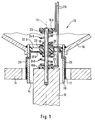
- FIG. 1 shows a drive system 10 for loudspeakers.
- the magnet system of this loudspeaker is only indicated in this illustration and shows only the upper pole plate 11 and the pole core 12.
- the pole plate 11 and the pole core 12 are arranged centrally to the loudspeaker central axis 13.
- the air gap 14 of the magnet system is formed between the outer jacket of the pole core 12 and the flanks of the pole plate 11.
- the conical membrane 15 is arranged centrally to the loudspeaker center axis.
- the large diameter of the membrane 15 is connected to the upper edge of the loudspeaker frame via a bead (not shown).
- the tubular voice coil former 16 is attached and connected to the small diameter of the membrane 15.
- the free end of the voice coil bobbin 16 protrudes into the air gap 14.
- the voice coil 17 is wound around the outer jacket of the voice coil bobbin 16.
- a rod 18 is placed centrally to the loudspeaker center axis 13 and in the direction of the diaphragm 15, which in the exemplary embodiment shown here for fastening reasons until it is inserted into the pole core 12.
- the free rag length of the rod 18 is limited at the top and bottom - facing the pole core 12 - in each case with a cap 19 O, 19 U formed of insulating material.
- a sleeve 20 is slidably arranged on the rod 18, which in the exemplary embodiment shown here is connected in one piece to a plate-shaped intermediate piece 21.
- the outer periphery of the intermediate piece 21 is connected to the inner jacket of the voice coil bobbin 16.
- the caps 19 O, 19 U are also provided with disks 23 on their sides facing the intermediate piece 21.
- a spiral spring 24 O, 24 U clamped from electrically conductive material.
- the two winding ends 25 of the voice coil 17 are guided to the disks 23 arranged on the intermediate piece 21, one winding end 25 with the disk 23 on the top 22 O and the other winding end 25 with the disk 23 on the underside 22 U of the intermediate piece 21 being conductive connected is.
- the two feed lines 26 coming from the signal source are guided through the bell of the diaphragm 15 to the disks 23 on the caps 19 O and 19 U, one feed line 26 being electrically conductively connected to the disk 23 on the cap 19 O and the other feed line being connected to the cap 19 U. So that the movement of the voice coil 17 or the membrane 15 is not hindered by the feed line 26 leading to the disk 23 of the lower cap 19 U, the intermediate piece 21 has a corresponding opening through which this feed line 26 is passed.
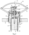
- FIG. 2 largely corresponds to the exemplary embodiment according to FIG. 1, so that components that have already been explained in connection with FIG. 1 are used in connection with FIG.
- This type of routing of the supply lines 26 to the respective disks 23 allows the smaller diameter of the membrane 15 to be hermetically sealed by means of a dust protection cap 28. As a result, the entire drive system 10 can be encapsulated. This is advantageous if the membrane 15 emits in dust-laden rooms.
- This dust protection cap 28 could also close the small diameter of the membrane 15 in the exemplary embodiment according to FIG. 1. It would be disadvantageous, however, that the supply lines 26 must be guided through the dust protection cap 28 and rub the opening areas in the dust protection cap 28 along the supply lines 26 during operation if the bushing is to be dust-tight. The latter on the one hand hinders the stroke of the membrane 15 and, on the other hand, has the effect that the dust tightness does not last long.
Landscapes
- Physics & Mathematics (AREA)
- Engineering & Computer Science (AREA)
- Acoustics & Sound (AREA)
- Signal Processing (AREA)
- Audible-Bandwidth Dynamoelectric Transducers Other Than Pickups (AREA)
Applications Claiming Priority (2)
| Application Number | Priority Date | Filing Date | Title |
|---|---|---|---|
| DE4241212 | 1992-12-08 | ||
| DE4241212A DE4241212A1 (de) | 1992-12-08 | 1992-12-08 | Schwingspulenkontaktierung für Lautsprecher |
Publications (3)
| Publication Number | Publication Date |
|---|---|
| EP0604766A2 true EP0604766A2 (fr) | 1994-07-06 |
| EP0604766A3 EP0604766A3 (fr) | 1995-01-25 |
| EP0604766B1 EP0604766B1 (fr) | 1997-02-19 |
Family
ID=6474633
Family Applications (1)
| Application Number | Title | Priority Date | Filing Date |
|---|---|---|---|
| EP93119081A Expired - Lifetime EP0604766B1 (fr) | 1992-12-08 | 1993-11-26 | Bonding pour bobine mobile pour haut-parleur |
Country Status (3)
| Country | Link |
|---|---|
| EP (1) | EP0604766B1 (fr) |
| JP (1) | JPH077793A (fr) |
| DE (2) | DE4241212A1 (fr) |
Cited By (1)
| Publication number | Priority date | Publication date | Assignee | Title |
|---|---|---|---|---|
| WO2018220066A1 (fr) * | 2017-05-30 | 2018-12-06 | Devialet | Haut-parleur électrodynamique comportant des fils d'alimentation électrique internes par rapport au porte-bobine |
Families Citing this family (5)
| Publication number | Priority date | Publication date | Assignee | Title |
|---|---|---|---|---|
| DE4419312A1 (de) * | 1994-06-01 | 1995-12-07 | Nokia Deutschland Gmbh | Lautsprecher |
| DE4437476A1 (de) * | 1994-10-20 | 1996-05-02 | Nokia Deutschland Gmbh | Verbindungsleitung |
| JP7226982B2 (ja) * | 2018-12-07 | 2023-02-21 | フォルシアクラリオン・エレクトロニクス株式会社 | 振動発生装置 |
| DE102020132146B4 (de) * | 2020-12-03 | 2025-04-24 | Vincent Chen | Lautsprecher mit Zentrierspinne, deren Elastizität lokal einstellbar ist, sowie Verfahren zu dessen Herstellung |
| RU210726U1 (ru) * | 2021-09-06 | 2022-04-28 | Олег Григорьевич Лобанов | Линейный динамический громкоговоритель |
Family Cites Families (7)
| Publication number | Priority date | Publication date | Assignee | Title |
|---|---|---|---|---|
| US4327257A (en) * | 1979-09-10 | 1982-04-27 | Schwartz Leslie H | Alignment device for electro-acoustical transducers |
| DE2946981C2 (de) * | 1979-11-21 | 1981-05-14 | Bm-Elektronik Meletzky Kg, 1000 Berlin | Elektroakustischer Wandler |
| DE3334442A1 (de) * | 1983-09-23 | 1985-04-11 | Telefunken Fernseh Und Rundfunk Gmbh, 3000 Hannover | Lautsprecher |
| NO172469C (no) * | 1984-01-25 | 1993-07-21 | Per Kirksaeter | Anordning for lydgjengivelsessystem |
| US4590333A (en) * | 1984-06-14 | 1986-05-20 | John Strohbeen | Multidriver loudspeaker |
| DE8604597U1 (de) * | 1986-02-20 | 1987-06-19 | Erede, Marco, Lucca | Dynamischer Lautsprecher für die Wiedergabe digitaler Tonsignale |
| EP0344975B2 (fr) * | 1988-06-02 | 2001-11-07 | Boaz Elieli | Transducteur électro-acoustique et haut-parleur |
-
1992
- 1992-12-08 DE DE4241212A patent/DE4241212A1/de not_active Withdrawn
-
1993
- 1993-11-26 EP EP93119081A patent/EP0604766B1/fr not_active Expired - Lifetime
- 1993-11-26 DE DE59305497T patent/DE59305497D1/de not_active Expired - Fee Related
- 1993-12-08 JP JP5308363A patent/JPH077793A/ja active Pending
Cited By (2)
| Publication number | Priority date | Publication date | Assignee | Title |
|---|---|---|---|---|
| WO2018220066A1 (fr) * | 2017-05-30 | 2018-12-06 | Devialet | Haut-parleur électrodynamique comportant des fils d'alimentation électrique internes par rapport au porte-bobine |
| FR3067201A1 (fr) * | 2017-05-30 | 2018-12-07 | Devialet | Haut-parleur electrodynamique comportant des fils d'alimentation electrique internes par rapport au porte-bobine |
Also Published As
| Publication number | Publication date |
|---|---|
| EP0604766B1 (fr) | 1997-02-19 |
| DE59305497D1 (de) | 1997-03-27 |
| JPH077793A (ja) | 1995-01-10 |
| DE4241212A1 (de) | 1994-06-09 |
| EP0604766A3 (fr) | 1995-01-25 |
Similar Documents
| Publication | Publication Date | Title |
|---|---|---|
| EP0480160B1 (fr) | Haut-parleur haute fréquence en forme de calotte | |
| DE19654156C2 (de) | Lautsprechereinheit und die Lautsprechereinheit verwendendes Lautsprechersystem | |
| DE3234692C2 (fr) | ||
| DE102007005696A1 (de) | Hilfskontakteinheit für einen magnetischen Kontaktgeber | |
| EP0604766B1 (fr) | Bonding pour bobine mobile pour haut-parleur | |
| EP0804048A2 (fr) | Haut-parleur | |
| DE3410373C2 (de) | Magnetbandkassette | |
| DE69023696T2 (de) | Ein elektronisches Bauteil mit einer Halterung. | |
| DE3330881A1 (de) | Halterung fuer eine insbesondere stromkompensierte ferrit-ringkerndrossel | |
| DE4129547C2 (de) | Cryostat | |
| EP0492142A2 (fr) | Système de commande pour un haut-parleur basse fréquence à excursion large | |
| EP0685979A2 (fr) | Membrane de centrage | |
| DE102017216024A1 (de) | Überspannungsableiter | |
| DE1290243B (de) | Kleinelektromotor, insbesondere fuer ein Magnettongeraet | |
| DE2505878A1 (de) | Spannhuelse | |
| WO2011098278A1 (fr) | Dispositif de compression d'un ensemble de piles à combustible au moyen d'éléments ressorts variables | |
| EP3544317B1 (fr) | Microphone à condensateur avec un anneau de céramique | |
| EP0471990B1 (fr) | Haut-parleur à double bobine | |
| DE19840374C2 (de) | Zentriermembran | |
| DE867405C (de) | Kondensator-Mikrofon mit federnd gehalterter Kapsel | |
| DE4137685A1 (de) | Drossel aus einer vielzahl von elementen | |
| DE1280439B (de) | Piezoelektrisches Festfrequenzfilter | |
| DE3900038A1 (de) | Lautsprecher-schwingspule | |
| DE4225854A1 (de) | Mittel-/Tiefton-Lautsprecher | |
| DE19851748A1 (de) | Lautsprecher |
Legal Events
| Date | Code | Title | Description |
|---|---|---|---|
| PUAI | Public reference made under article 153(3) epc to a published international application that has entered the european phase |
Free format text: ORIGINAL CODE: 0009012 |
|
| AK | Designated contracting states |
Kind code of ref document: A2 Designated state(s): BE DE FR GB IT SE |
|
| PUAL | Search report despatched |
Free format text: ORIGINAL CODE: 0009013 |
|
| AK | Designated contracting states |
Kind code of ref document: A3 Designated state(s): BE DE FR GB IT SE |
|
| 17P | Request for examination filed |
Effective date: 19950512 |
|
| GRAG | Despatch of communication of intention to grant |
Free format text: ORIGINAL CODE: EPIDOS AGRA |
|
| 17Q | First examination report despatched |
Effective date: 19960619 |
|
| GRAH | Despatch of communication of intention to grant a patent |
Free format text: ORIGINAL CODE: EPIDOS IGRA |
|
| GRAH | Despatch of communication of intention to grant a patent |
Free format text: ORIGINAL CODE: EPIDOS IGRA |
|
| GRAA | (expected) grant |
Free format text: ORIGINAL CODE: 0009210 |
|
| AK | Designated contracting states |
Kind code of ref document: B1 Designated state(s): BE DE FR GB IT SE |
|
| PG25 | Lapsed in a contracting state [announced via postgrant information from national office to epo] |
Ref country code: FR Free format text: THE PATENT HAS BEEN ANNULLED BY A DECISION OF A NATIONAL AUTHORITY Effective date: 19970219 |
|
| ITF | It: translation for a ep patent filed | ||
| REF | Corresponds to: |
Ref document number: 59305497 Country of ref document: DE Date of ref document: 19970327 |
|
| GBT | Gb: translation of ep patent filed (gb section 77(6)(a)/1977) |
Effective date: 19970312 |
|
| ET | Fr: translation filed | ||
| PG25 | Lapsed in a contracting state [announced via postgrant information from national office to epo] |
Ref country code: GB Free format text: LAPSE BECAUSE OF NON-PAYMENT OF DUE FEES Effective date: 19971126 |
|
| PG25 | Lapsed in a contracting state [announced via postgrant information from national office to epo] |
Ref country code: SE Free format text: LAPSE BECAUSE OF NON-PAYMENT OF DUE FEES Effective date: 19971127 |
|
| PG25 | Lapsed in a contracting state [announced via postgrant information from national office to epo] |
Ref country code: BE Free format text: LAPSE BECAUSE OF NON-PAYMENT OF DUE FEES Effective date: 19971130 |
|
| PLBE | No opposition filed within time limit |
Free format text: ORIGINAL CODE: 0009261 |
|
| 26N | No opposition filed | ||
| BERE | Be: lapsed |
Owner name: NOKIA TECHNOLOGY G.M.B.H. Effective date: 19971130 |
|
| GBPC | Gb: european patent ceased through non-payment of renewal fee |
Effective date: 19971126 |
|
| PG25 | Lapsed in a contracting state [announced via postgrant information from national office to epo] |
Ref country code: DE Free format text: LAPSE BECAUSE OF NON-PAYMENT OF DUE FEES Effective date: 19980801 |
|
| EUG | Se: european patent has lapsed |
Ref document number: 93119081.3 |
|
| REG | Reference to a national code |
Ref country code: FR Ref legal event code: ST |
|
| PG25 | Lapsed in a contracting state [announced via postgrant information from national office to epo] |
Ref country code: IT Free format text: LAPSE BECAUSE OF NON-PAYMENT OF DUE FEES;WARNING: LAPSES OF ITALIAN PATENTS WITH EFFECTIVE DATE BEFORE 2007 MAY HAVE OCCURRED AT ANY TIME BEFORE 2007. THE CORRECT EFFECTIVE DATE MAY BE DIFFERENT FROM THE ONE RECORDED. Effective date: 20051126 |