EP0605975B1 - Système de contrÔle de température pour une brise chauffée dans un procédé de moulage par injection sans carotte et son procédé de contrÔle de température - Google Patents
Système de contrÔle de température pour une brise chauffée dans un procédé de moulage par injection sans carotte et son procédé de contrÔle de température Download PDFInfo
- Publication number
- EP0605975B1 EP0605975B1 EP93310159A EP93310159A EP0605975B1 EP 0605975 B1 EP0605975 B1 EP 0605975B1 EP 93310159 A EP93310159 A EP 93310159A EP 93310159 A EP93310159 A EP 93310159A EP 0605975 B1 EP0605975 B1 EP 0605975B1
- Authority
- EP
- European Patent Office
- Prior art keywords
- temperature
- hot nozzle
- nozzle
- temperature control
- power
- Prior art date
- Legal status (The legal status is an assumption and is not a legal conclusion. Google has not performed a legal analysis and makes no representation as to the accuracy of the status listed.)
- Expired - Lifetime
Links
- 238000000465 moulding Methods 0.000 title claims description 28
- 238000000034 method Methods 0.000 title claims description 16
- 238000010438 heat treatment Methods 0.000 claims description 38
- 239000011347 resin Substances 0.000 claims description 15
- 229920005989 resin Polymers 0.000 claims description 15
- 238000001746 injection moulding Methods 0.000 claims description 14
- 238000011144 upstream manufacturing Methods 0.000 claims description 3
- 238000002347 injection Methods 0.000 description 5
- 239000007924 injection Substances 0.000 description 5
- 238000004891 communication Methods 0.000 description 3
- 238000010586 diagram Methods 0.000 description 2
- 230000001105 regulatory effect Effects 0.000 description 2
- 101000892301 Phomopsis amygdali Geranylgeranyl diphosphate synthase Proteins 0.000 description 1
- 238000010276 construction Methods 0.000 description 1
- 238000001816 cooling Methods 0.000 description 1
- 230000000694 effects Effects 0.000 description 1
- 239000000463 material Substances 0.000 description 1
- 239000007769 metal material Substances 0.000 description 1
- 238000010008 shearing Methods 0.000 description 1
- 230000008054 signal transmission Effects 0.000 description 1
Images
Classifications
-
- B—PERFORMING OPERATIONS; TRANSPORTING
- B29—WORKING OF PLASTICS; WORKING OF SUBSTANCES IN A PLASTIC STATE IN GENERAL
- B29C—SHAPING OR JOINING OF PLASTICS; SHAPING OF MATERIAL IN A PLASTIC STATE, NOT OTHERWISE PROVIDED FOR; AFTER-TREATMENT OF THE SHAPED PRODUCTS, e.g. REPAIRING
- B29C45/00—Injection moulding, i.e. forcing the required volume of moulding material through a nozzle into a closed mould; Apparatus therefor
- B29C45/17—Component parts, details or accessories; Auxiliary operations
- B29C45/76—Measuring, controlling or regulating
- B29C45/78—Measuring, controlling or regulating of temperature
-
- B—PERFORMING OPERATIONS; TRANSPORTING
- B29—WORKING OF PLASTICS; WORKING OF SUBSTANCES IN A PLASTIC STATE IN GENERAL
- B29C—SHAPING OR JOINING OF PLASTICS; SHAPING OF MATERIAL IN A PLASTIC STATE, NOT OTHERWISE PROVIDED FOR; AFTER-TREATMENT OF THE SHAPED PRODUCTS, e.g. REPAIRING
- B29C45/00—Injection moulding, i.e. forcing the required volume of moulding material through a nozzle into a closed mould; Apparatus therefor
- B29C45/17—Component parts, details or accessories; Auxiliary operations
- B29C45/26—Moulds
- B29C45/27—Sprue channels ; Runner channels or runner nozzles
- B29C45/2737—Heating or cooling means therefor
- B29C2045/274—Thermocouples or heat sensors
-
- B—PERFORMING OPERATIONS; TRANSPORTING
- B29—WORKING OF PLASTICS; WORKING OF SUBSTANCES IN A PLASTIC STATE IN GENERAL
- B29C—SHAPING OR JOINING OF PLASTICS; SHAPING OF MATERIAL IN A PLASTIC STATE, NOT OTHERWISE PROVIDED FOR; AFTER-TREATMENT OF THE SHAPED PRODUCTS, e.g. REPAIRING
- B29C45/00—Injection moulding, i.e. forcing the required volume of moulding material through a nozzle into a closed mould; Apparatus therefor
- B29C45/17—Component parts, details or accessories; Auxiliary operations
- B29C45/26—Moulds
- B29C45/27—Sprue channels ; Runner channels or runner nozzles
- B29C45/2737—Heating or cooling means therefor
- B29C2045/2753—Heating means and cooling means, e.g. heating the runner nozzle and cooling the nozzle tip
-
- B—PERFORMING OPERATIONS; TRANSPORTING
- B29—WORKING OF PLASTICS; WORKING OF SUBSTANCES IN A PLASTIC STATE IN GENERAL
- B29C—SHAPING OR JOINING OF PLASTICS; SHAPING OF MATERIAL IN A PLASTIC STATE, NOT OTHERWISE PROVIDED FOR; AFTER-TREATMENT OF THE SHAPED PRODUCTS, e.g. REPAIRING
- B29C2945/00—Indexing scheme relating to injection moulding, i.e. forcing the required volume of moulding material through a nozzle into a closed mould
- B29C2945/76—Measuring, controlling or regulating
- B29C2945/76003—Measured parameter
- B29C2945/7604—Temperature
-
- B—PERFORMING OPERATIONS; TRANSPORTING
- B29—WORKING OF PLASTICS; WORKING OF SUBSTANCES IN A PLASTIC STATE IN GENERAL
- B29C—SHAPING OR JOINING OF PLASTICS; SHAPING OF MATERIAL IN A PLASTIC STATE, NOT OTHERWISE PROVIDED FOR; AFTER-TREATMENT OF THE SHAPED PRODUCTS, e.g. REPAIRING
- B29C2945/00—Indexing scheme relating to injection moulding, i.e. forcing the required volume of moulding material through a nozzle into a closed mould
- B29C2945/76—Measuring, controlling or regulating
- B29C2945/76177—Location of measurement
- B29C2945/76254—Mould
- B29C2945/76274—Mould runners, nozzles
-
- B—PERFORMING OPERATIONS; TRANSPORTING
- B29—WORKING OF PLASTICS; WORKING OF SUBSTANCES IN A PLASTIC STATE IN GENERAL
- B29C—SHAPING OR JOINING OF PLASTICS; SHAPING OF MATERIAL IN A PLASTIC STATE, NOT OTHERWISE PROVIDED FOR; AFTER-TREATMENT OF THE SHAPED PRODUCTS, e.g. REPAIRING
- B29C2945/00—Indexing scheme relating to injection moulding, i.e. forcing the required volume of moulding material through a nozzle into a closed mould
- B29C2945/76—Measuring, controlling or regulating
- B29C2945/76494—Controlled parameter
- B29C2945/76531—Temperature
-
- B—PERFORMING OPERATIONS; TRANSPORTING
- B29—WORKING OF PLASTICS; WORKING OF SUBSTANCES IN A PLASTIC STATE IN GENERAL
- B29C—SHAPING OR JOINING OF PLASTICS; SHAPING OF MATERIAL IN A PLASTIC STATE, NOT OTHERWISE PROVIDED FOR; AFTER-TREATMENT OF THE SHAPED PRODUCTS, e.g. REPAIRING
- B29C2945/00—Indexing scheme relating to injection moulding, i.e. forcing the required volume of moulding material through a nozzle into a closed mould
- B29C2945/76—Measuring, controlling or regulating
- B29C2945/76494—Controlled parameter
- B29C2945/76551—Time
-
- B—PERFORMING OPERATIONS; TRANSPORTING
- B29—WORKING OF PLASTICS; WORKING OF SUBSTANCES IN A PLASTIC STATE IN GENERAL
- B29C—SHAPING OR JOINING OF PLASTICS; SHAPING OF MATERIAL IN A PLASTIC STATE, NOT OTHERWISE PROVIDED FOR; AFTER-TREATMENT OF THE SHAPED PRODUCTS, e.g. REPAIRING
- B29C2945/00—Indexing scheme relating to injection moulding, i.e. forcing the required volume of moulding material through a nozzle into a closed mould
- B29C2945/76—Measuring, controlling or regulating
- B29C2945/76655—Location of control
- B29C2945/76732—Mould
- B29C2945/76752—Mould runners, nozzles
-
- B—PERFORMING OPERATIONS; TRANSPORTING
- B29—WORKING OF PLASTICS; WORKING OF SUBSTANCES IN A PLASTIC STATE IN GENERAL
- B29C—SHAPING OR JOINING OF PLASTICS; SHAPING OF MATERIAL IN A PLASTIC STATE, NOT OTHERWISE PROVIDED FOR; AFTER-TREATMENT OF THE SHAPED PRODUCTS, e.g. REPAIRING
- B29C2945/00—Indexing scheme relating to injection moulding, i.e. forcing the required volume of moulding material through a nozzle into a closed mould
- B29C2945/76—Measuring, controlling or regulating
- B29C2945/76929—Controlling method
- B29C2945/76939—Using stored or historical data sets
-
- B—PERFORMING OPERATIONS; TRANSPORTING
- B29—WORKING OF PLASTICS; WORKING OF SUBSTANCES IN A PLASTIC STATE IN GENERAL
- B29C—SHAPING OR JOINING OF PLASTICS; SHAPING OF MATERIAL IN A PLASTIC STATE, NOT OTHERWISE PROVIDED FOR; AFTER-TREATMENT OF THE SHAPED PRODUCTS, e.g. REPAIRING
- B29C45/00—Injection moulding, i.e. forcing the required volume of moulding material through a nozzle into a closed mould; Apparatus therefor
- B29C45/17—Component parts, details or accessories; Auxiliary operations
- B29C45/26—Moulds
- B29C45/27—Sprue channels ; Runner channels or runner nozzles
- B29C45/2737—Heating or cooling means therefor
Definitions
- the present invention relates to a temperature control system and a temperature control method for a hot nozzle used in a runner-less injection moulding process of a plastic.
- the applicant of the present application has proposed an improved hot nozzle in U.S. Patent No. 4 648 833.
- the preambles of the independent claims are based upon the disclosure of this document.
- the hot nozzle proposed in this U.S. patent does not require an external heater and can be rapidly heated or cooled in a short time.
- the nozzle includes a nozzle portion and a base portion.
- the nozzle portion is adapted to be inserted into a bore of a mould which is formed in communication with a mould cavity.
- the base portion serves to provide communication with the nozzle portion for the flow of molten resin injected from an injection moulding machine.
- a pair of longitudinal slits extend over the length of the nozzle except a front end of the nozzle portion. Electric current is applied between both ends of the base portion divided by the slits, so that the nozzle portion is heated by itself.
- the front end of the nozzle is liable to be influenced by the temperature of the mold since the front end normally contacts the mold during the molding process.
- the hot nozzle is formed of a relatively thin metal material and has relatively small heat capacity. This may cause temperature difference between the front end and a part of the nozzle on the side of the base portion. Particularly, when the mold is cooled to take out the molded product, the molten resin is solidified in the front end, so that no further injection process can be performed.
- the hot nozzle involves the problem that it is very difficult to control its temperature.
- an object of the present invention to provide a temperature control system for a hot nozzle which is operable to reliably control the temperature of the hot nozzle.
- a temperature control system for a hot nozzle for use in a runner-less molding process of a plastic using an injection molding machine including a nozzle portion adopted to be inserted into a bore formed in a mold and communicating with a mold cavity, a base portion for the flow of a molten resin of the plastic from the injection molding machine to the nozzle portion, the hot nozzle being divided substantially into two sections by a pair of slits which extend over the length of the hot nozzle except the front end of the nozzle portion, so that the nozzle portion can be heated through application of electric power between both sides of the base portion separated by the slits, comprising:
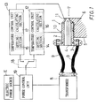
- the hot nozzle 1 includes a nozzle portion 2 tapered at its front end and a base portion 3 formed integrally with the nozzle portion 2.
- the hot nozzle 1 is divided substantially into two parts by a pair of longitudinal slits 4 extending over the length of the hot nozzle 1 except the front end of the nozzle portion 2.
- the outer surface of the hot nozzle 1 is coated with a material (not shown) having both dielectric and adiabatic properties.
- the construction of the hot nozzle 1 is disclosed in detail in U.S. Patent No. 4,648,833, and therefore, a more detailed explanation of the hot nozzle 1 is omitted.
- the nozzle portion 2 is inserted into a longitudinal bore 6 formed in a mold 5 in communication with a mold cavity 7, so that the front end of the nozzle portion 2 fronts on the cavity 7.
- the base portion 3 is connected to an injection nozzle (not shown) of an injection molding machine via a manifold, so that the molten resin injected from the injection molding machine enters the hot nozzle 1 via the manifold and is thereafter injected into the cavity 7.
- Lead wires 9 led from a transformer 8 are connected to the base portion 3 on both sides divided by the slits 4, so that the hot nozzle 1 is heated by the application of an electric power having low voltage and high current through the lead wires 9.
- Thermocouples 10 and 11 are attached to the nozzle portion 2 of the hot nozzle 1 at the front end and at a middle portion of the nozzle portion 2 in the longitudinal direction, respectively.
- the thermocouples 10 and 11 are connected to temperature control units 12 and 13, respectively.
- the temperature control units 12 and 13 include setting sections 14 and 15 operable by an operator for setting target temperatures (target temperatures Ta and Tb shown in FIG. 2(a)), respectively.
- the temperature control units 12 and 13 also include calculation sections 14 and 16 which are operable to compare the temperature detected by the thermocouples 10 and 11 with the target temperature and to obtain current signals (DC 4 to 20 mA) corresponding to the temperature differences therebetween through PID calculation process, respectively.
- the temperature control units 12 and 13 are connected to a power control unit 19 via a changeover switch 18.
- the changeover switch 18 is operable to selectively connect either one of the temperature control units 12 and 13 to the power control unit 19 such that one of the current signals from the calculation sections 14 and 16 of the temperature control units 12 and 13 is selective
- a primary voltage of AC 100 to 240 V is supplied from a power source E to the power control unit 19.
- the power control unit 19 regulates the primary voltage to a voltage corresponding to the temperature difference based on the selected one of the current signals through a phase control by means of a triac, etc.
- the voltage thus regulated is outputted to a transformer 8 which transforms the regulated voltage into an electric power having relatively low voltage and relatively high current appropriate for supply to the base portion 3 of the hot nozzle 1 for heating the same.
- the power control unit 19 includes a converter for converting the power to be supplied to the transformer 8 into power having high frequency, so that the transformer 8 may have a smaller size.
- each of the temperature control units 12 and 13 is operable to output a constant current signal during a predetermined time within the molding cycle, independently of the current signal obtained based on the temperature difference.
- each of the setting sections 14 and 15 is operable to supply a constant heating current to the hot nozzle 1.
- the temperature control unit 12 outputs a constant current signal so as to provide constant heating current Ic as will be hereinafter explained.
- each of the setting sections 14 and 15 is equipped with a timer which is operable to set a period of supplying such a constant heating current.
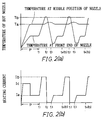
- the changeover switch 18 is controlled to be switched in accordance with a signal from a control panel (not shown) of the injection molding machine. Such a control of the changeover switch 18 will now be explained with reference to FIGS. 2(a) and 2(b).
- the changeover switch 18 is switched to the temperature control unit 12, and the temperature control unit 12 compares the temperature detected by the thermocouple 18 at the central position of the nozzle portion 2 with set temperature Ta.
- the temperature control unit 12 does not output the current signal corresponding to the temperature difference but outputs the constant current signal corresponding to constant heating current Ic which is higher than the heating current obtained based on the temperature difference.
- the constant current signal for constant heating current Ic is kept to be outputted until the temperature of the hot nozzle 1 at its central position reaches set temperature Ta.
- heating current Ia based on the temperature difference is supplied to maintain set temperature Ta.
- the temperature at the front end of the nozzle portion 2 is lower than set temperature Ta because of the cooling effect by the mold 5.
- the changeover switch 18 is switched to the temperature control unit 13. Then, the temperature detected by the thermocouple 11 at the front end of the nozzle portion 2 is compared with set temperature Tb, so that the hot nozzle 1 is heated by the heating current corresponding to the temperature difference. After the temperature has reached set temperature Tb, heating current Ib is supplied to maintain set temperature Tb. The heating current is interrupted or reduced to zero by means of a timer at the same time when the injection process of the molten resin to the mold cavity 7 is finished at timing t2 in FIG. 2(b).
- the front end of the nozzle portion 2 is heated to reach set temperature Tb which permits the molten resin injected from the molding machine to be smoothly flown into the cavity 7 without substantial pressure loss.
- Tb set temperature
- the front end of the nozzle portion 2 is cooled by the mold 5, so that the molten resin within the front end of the nozzle portion 2 is solidified. Therefore, subsequent operations for opening the mold and for taking the product out of the mold can be performed without any problem, and cobwebbing or leakage of resin from the nozzle portion 2 can be prevented.
- the changeover switch 18 is switched to the temperature control unit 12 for preheating the solidified resin within the nozzle portion 2.
- heating current Ic higher than the heating current determined based on the temperature difference as described above is to be supplied.
- the temperature at the central position of the nozzle 2 may exceed set temperature Ta because of the temperature of the molten resin within the nozzle 2 and the heat produced by shearing friction at a gate formed by the front end of the nozzle 2.
- the temperature control unit 12 outputs the current signal corresponding to the temperature difference so as to provide the heating current lower than heating current Ic and thereafter maintains the temperature by heating current Ia as described above.
- the changeover switch 18 is switched from the temperature control unit 12 to the temperature control unit 13, and the hot nozzle 1 is heated by the heating current corresponding to the temperature difference.
- heating current Ib is supplied to maintain set temperature Tb in the same manner as described above.
- the heating current is interrupted or reduced to zero by means of the timer at the same time when the injection process of the molten resin to the mold cavity 7 is finished.
- the power control unit 19 may directly supply an appropriate heating current to the hot nozzle 1 without intervening of the temperature control unit 13 to compensate for the time lag in the heating operation because of transmission of signal between the temperature control unit 13 and the power control unit 19, and the control based on the current signal from the temperature control unit 13 may be thereafter performed.
- the control of temperature of the hot nozzle 1 is performed with the detected temperature at the front end of the nozzle portion 2 and the detected temperature at the central position being utilized for rapid heating and for keeping the temperature according to the various steps in the molding cycle.
- the temperature control of the hot nozzle 1 can therefore be accurately performed, so that the quality of the product can be improved.
- the constant current signal for constant heating current Ic is supplied in place of the current signal which is determined based on the temperature difference. Further, such a constant heating current is changed to the heating current determined based on the temperature difference. Therefore, the molding operation can be effectively performed.
Landscapes
- Engineering & Computer Science (AREA)
- Manufacturing & Machinery (AREA)
- Mechanical Engineering (AREA)
- Injection Moulding Of Plastics Or The Like (AREA)
- Moulds For Moulding Plastics Or The Like (AREA)
Claims (10)
- Système de réglage de température pour une buse chaude (1) à utiliser dans un procédé de moulage sans canal pour matière plastique en utilisant une machine de moulage par injection, la buse chaude (1) comprenant une partie de buse (2) agencée pour être introduite dans un trou (6) ménagé dans un moule (5) et communiquant avec une cavité de moule (7), une partie de base (3) pour l'écoulement d'une résine fondue de la matière plastique depuis la machine de moulage par injection jusqu'à la partie de buse (2), la buse chaude (1) étant divisée sensiblement en deux sections par une paire de fentes (4) qui s'étendent sur la longueur de la buse chaude (1) à l'exception de l'extrémité avant de la partie de buse (2), d'une façon telle que la partie de buse (2) puisse être chauffée par application d'un courant électrique entre les deux côtés de la partie de base (3) séparée par les fentes (4),
caractérisé en ce qu'il comprend en outre :des premiers moyens de détection de température (11) servant à détecter la température de la buse chaude (1) à l'extrémité avant de celle-ci,des seconds moyens de détection de température (10) servant à détecter la température de la buse chaude (1) en un emplacement situé en amont de l'extrémité avant,des moyens de délivrance de signaux de commande (13, 12) servant à comparer la température détectée par les premiers et les seconds moyens de détection de température (11, 10) respectivement avec une première température fixée et une seconde température fixée, et servant à délivrer respectivement des premier et second signaux de commande correspondant aux différences de température existant entre celles-ci,des moyens d'alimentation en courant (8) connectés aux moyens de délivrance de signaux de commande (13, 12) et servant à fournir à la base (3) de la buse chaude (1) un courant servant à chauffer la buse chaude (1) en réponse aux premier et second signaux de commande etdes moyens de commutation (18) connectés entre les moyens de délivrance de signaux de commande (13, 12) et les moyens d'alimentation en courant (8) et pouvant être manoeuvrés pour appliquer sélectivement l'un ou l'autre des premier et second signaux de commande de température aux moyens d'alimentation en courant (8) en fonction du cycle de moulage de la machine de moulage. - Système de réglage de température tel que défini à la revendication 1, dans lequel les moyens d'alimentation en courant comprennent des moyens de réglage de courant (19) et un transformateur (8), les moyens de réglage de courant (19) peuvent être commandés pour assurer une régulation du courant provenant d'une source de courant (E) d'une manière correspondant aux premier et second signaux de réglage de température, et le transformateur (8) est agencé pour transformer le courant provenant des moyens de réglage de courant (19) en un courant présentant une faible tension et une intensité élevée.
- Système de réglage de température tel que défini à la revendication 2, dans lequel les moyens de réglage de courant (19) comprennent des moyens servant à convertir le courant à fournir au transformateur (8) en un courant présentant une fréquence élevée, d'une façon telle que le transformateur (8) ait de très petites dimensions.
- Système de réglage de température tel que défini à la revendication 1, 2 ou 3, dans lequel les seconds moyens de détection de température (10) sont agencés pour détecter la température de la buse chaude (1) pratiquement à l'emplacement central de la partie de buse (2) suivant la direction longitudinale.
- Système de réglage de température tel que défini à la revendication 1, 2, 3 ou 4, dans lequel les moyens de délivrance de signaux de réglage comprennent une première unité de réglage de température (13) et une seconde unité de réglage de température (12) connectées respectivement aux premiers moyens de détection de température (11) et aux seconds moyens de détection de température (10), chacune des première et seconde unités de réglage (13, 12) comprend des moyens de fixation (15, 14) servant à fixer une température cible et des moyens de calcul (17, 16) servant à calculer une intensité de courant de chauffage appliquée à la buse chaude (1) sur la base de la différence de température détectée.
- Système de réglage de température tel que défini à la revendication 5, dans lequel au moins l'une des première et seconde unités de réglage de température (13, 12) peut être commandée pour délivrer un signal de réglage constant préfixé servant à fournir une intensité de courant de chauffage constante à la buse chaude (1) pendant une période préfixée du cycle de moulage, à la place du signal de réglage obtenu sur la base de la différence de température.
- Système de réglage de température tel que défini à la revendication 6, dans lequel une minuterie est prévue pour fixer la période préfixée.
- Système de réglage de température tel que défini à l'une quelconque des revendications précédentes, dans lequel les moyens de commutation (18) sont connectés à un panneau de commande de la machine de moulage par injection et les moyens de commutation (18) peuvent être commandés au moyen d'un signal de cycle de moulage délivré par le panneau de commande.
- Procédé de réglage de la température d'une buse chaude (1) à utiliser dans un procédé de moulage sans canal pour matière plastique en utilisant une machine de moulage par injection, la buse chaude (1) comprenant une partie de buse (2) agencée pour être introduite dans un trou (6) ménagé dans un moule (5) et communiquant avec une cavité de moule (7), une partie de base (3) pour l'écoulement d'une résine fondue de la matière plastique depuis la machine de moulage par injection jusqu'à la partie de buse (2), la buse chaude (1) étant divisée sensiblement en deux sections par une paire de fentes (4) qui s'étendent sur la longueur de la buse chaude (1) à l'exception de l'extrémité avant de la partie de buse (2), d'une façon telle que la partie de buse (2) puisse être chauffée par application d'un courant électrique entre les deux côtés de la partie de base (3) séparée par les fentes (4),
caractérisé en ce qu'il comprend les opérations consistant :à détecter la température de la buse chaude (1) en au moins deux emplacements comprenant un emplacement situé à une extrémité avant de la partie de buse (2) et un emplacement situé en amont de l'extrémité avant,à comparer les températures détectées à des températures fixées et à calculer respectivement des intensités de courant de chauffage sur la base des différences existant entre celles-ci,à sélectionner l'une ou l'autre des intensités de courant de chauffage en fonction du cycle de moulage età appliquer l'intensité de courant de chauffage sélectionnée à la buse chaude (1) pour chauffer celle-ci. - Procédé de réglage de température tel que défini à la revendication 9, selon lequel une intensité de courant de chauffage constante préfixée est appliquée à la buse chaude (1) à la place de ladite intensité de courant de chauffage pendant une période préfixée du cycle de moulage.
Applications Claiming Priority (2)
| Application Number | Priority Date | Filing Date | Title |
|---|---|---|---|
| JP4356022A JPH0832424B2 (ja) | 1992-12-18 | 1992-12-18 | プラスチックのランナレス射出成形のためのホットノズルの温度制御装置 |
| JP356022/92 | 1992-12-18 |
Publications (2)
| Publication Number | Publication Date |
|---|---|
| EP0605975A1 EP0605975A1 (fr) | 1994-07-13 |
| EP0605975B1 true EP0605975B1 (fr) | 1997-10-22 |
Family
ID=18446933
Family Applications (1)
| Application Number | Title | Priority Date | Filing Date |
|---|---|---|---|
| EP93310159A Expired - Lifetime EP0605975B1 (fr) | 1992-12-18 | 1993-12-16 | Système de contrÔle de température pour une brise chauffée dans un procédé de moulage par injection sans carotte et son procédé de contrÔle de température |
Country Status (5)
| Country | Link |
|---|---|
| US (1) | US5435711A (fr) |
| EP (1) | EP0605975B1 (fr) |
| JP (1) | JPH0832424B2 (fr) |
| KR (1) | KR100285094B1 (fr) |
| DE (1) | DE69314759T2 (fr) |
Families Citing this family (11)
| Publication number | Priority date | Publication date | Assignee | Title |
|---|---|---|---|---|
| US5843495A (en) * | 1994-08-08 | 1998-12-01 | Yamada; Fujio | Hot nozzle for use with a side-gate runnerless injection molding system |
| JP3024696B2 (ja) * | 1994-09-01 | 2000-03-21 | ファナック株式会社 | 射出成形機の温度制御方法 |
| JP2835030B2 (ja) * | 1995-08-10 | 1998-12-14 | 株式会社名機製作所 | 射出成形機のノズル温度制御装置 |
| JPH09174553A (ja) * | 1995-12-22 | 1997-07-08 | Isago Miura | 可塑化原料の間歇的加熱装置における制御装置 |
| KR100415147B1 (ko) * | 2000-11-27 | 2004-01-14 | 유도실업주식회사 | 온조기를 이용한 사출금형의 온도 조절방법 |
| CA2471439A1 (fr) * | 2003-06-20 | 2004-12-20 | Mold-Masters Limited | Controleur de moule et de canal chauffant sur platine de machine |
| ITTO20050158A1 (it) * | 2005-03-11 | 2006-09-12 | Incos Spa | Sistema di controllo energetico per apparecchiature di stampaggio ad iniezione di materie plastiche |
| DE102007011461A1 (de) * | 2007-03-07 | 2008-09-11 | Breyer Gmbh Maschinenfabrik | Extrusionsdüse zur Herstellung von Hohlkammerprofilen |
| KR101288686B1 (ko) * | 2007-08-24 | 2013-07-22 | 허스키 인젝션 몰딩 시스템즈 리미티드 | 용탕 분배 네트웍 내에서의 용탕 유동을 제어하기 위한 장치 |
| WO2012110859A1 (fr) * | 2011-02-17 | 2012-08-23 | Meiban International Pte. Ltd. | Micro-dispositif de réglage de température |
| JP5926204B2 (ja) * | 2013-01-17 | 2016-05-25 | ファナック株式会社 | 型締機構の温度制御装置を有する射出成形機 |
Family Cites Families (9)
| Publication number | Priority date | Publication date | Assignee | Title |
|---|---|---|---|---|
| USRE31903E (en) * | 1979-06-15 | 1985-06-04 | Crompton & Knowles Corporation | Extruder temperature controller |
| JPS58148740A (ja) * | 1982-02-27 | 1983-09-03 | Fujikura Ltd | プラスチツク成形機の樹脂温度制御方法 |
| JPS6164419A (ja) * | 1984-09-07 | 1986-04-02 | Jiyuuou Shoji Kk | ホットランナ−式射出成形装置 |
| DE3407894C2 (de) * | 1984-03-03 | 1987-02-05 | Joachim Friedrich 6000 Frankfurt Knauer | Kunststoff-Spritzgießvorrichtung mit Spritzgießmaschine und Spritzgießform für angußloses Spritzgießen |
| JPS613720A (ja) * | 1984-06-18 | 1986-01-09 | Fujio Yamada | プラスチックのランナレス射出成形のためのホットランナシステムにおけるホットノズル |
| US4648833A (en) * | 1985-10-17 | 1987-03-10 | Fujio Yamada | Hot nozzle for runnerless mold |
| JPS62184826A (ja) * | 1986-02-12 | 1987-08-13 | Sumitomo Heavy Ind Ltd | ノズル温度制御方法 |
| JPS62199419A (ja) * | 1986-02-28 | 1987-09-03 | Sumitomo Heavy Ind Ltd | プラスチツク成形機の加熱方法 |
| US4882469A (en) * | 1988-09-28 | 1989-11-21 | Panos Trakas | Internally heated sprue bushing assembly with a unitary bushing casing core element |
-
1992
- 1992-12-18 JP JP4356022A patent/JPH0832424B2/ja not_active Expired - Lifetime
-
1993
- 1993-12-16 DE DE69314759T patent/DE69314759T2/de not_active Expired - Fee Related
- 1993-12-16 US US08/167,040 patent/US5435711A/en not_active Expired - Fee Related
- 1993-12-16 EP EP93310159A patent/EP0605975B1/fr not_active Expired - Lifetime
- 1993-12-17 KR KR1019930028301A patent/KR100285094B1/ko not_active Expired - Fee Related
Also Published As
| Publication number | Publication date |
|---|---|
| EP0605975A1 (fr) | 1994-07-13 |
| JPH0832424B2 (ja) | 1996-03-29 |
| JPH06182841A (ja) | 1994-07-05 |
| KR940013788A (ko) | 1994-07-16 |
| KR100285094B1 (ko) | 2001-04-02 |
| DE69314759T2 (de) | 1998-05-28 |
| DE69314759D1 (de) | 1997-11-27 |
| US5435711A (en) | 1995-07-25 |
Similar Documents
| Publication | Publication Date | Title |
|---|---|---|
| US4726751A (en) | Hot-runner plastic injection molding system | |
| US5772933A (en) | Method for tempering an injection mold having at least one heated nozzle or hot runner | |
| US5435711A (en) | Temperature control device for a hot nozzle used in a runnerless molding process | |
| CA2215919A1 (fr) | Appareil pour le chauffage d'un moule dans un systeme de moulage par injection | |
| JP2004525794A (ja) | 被成形部材の収縮を制御する方法 | |
| EP0573749B1 (fr) | Dispositif de chauffage intermittent pour des fluides plastifiés dans les moulages par injection ou similaires | |
| US6107610A (en) | Power factor correction system for a resistive load device | |
| JPH0531449B2 (fr) | ||
| JPH09150444A (ja) | ホットランナーノズルの温度制御方法 | |
| JPH04138234A (ja) | 射出成形機の制御装置 | |
| JP2003205539A (ja) | 射出成形機の予熱制御装置 | |
| JPH0360298B1 (fr) | ||
| JPH0437767B1 (fr) | ||
| JPS5933102B2 (ja) | 射出成形の制御装置 | |
| JPH0427934B1 (fr) | ||
| JPH0557769A (ja) | 射出成形機の金型温度調節装置 | |
| JPH0414865B2 (fr) | ||
| JPH0513543Y2 (fr) | ||
| JPH03104609A (ja) | プラスチック成形型装置 | |
| JPS6487319A (en) | Method for controlling temperature of injection molder | |
| JP2002059458A (ja) | 射出成形機 | |
| JPS60206612A (ja) | ランナ−レス射出成形方法およびホツトランナ− | |
| JPH04189519A (ja) | ホットランナー式射出成形装置 | |
| JPH039826A (ja) | ホットランナー式射出成形装置用の間欠加熱時間割出し方法及び装置 | |
| JPH11254443A (ja) | 温度制御用電熱線内蔵金型 |
Legal Events
| Date | Code | Title | Description |
|---|---|---|---|
| PUAI | Public reference made under article 153(3) epc to a published international application that has entered the european phase |
Free format text: ORIGINAL CODE: 0009012 |
|
| AK | Designated contracting states |
Kind code of ref document: A1 Designated state(s): DE FR GB IT SE |
|
| 17P | Request for examination filed |
Effective date: 19941212 |
|
| 17Q | First examination report despatched |
Effective date: 19960716 |
|
| GRAG | Despatch of communication of intention to grant |
Free format text: ORIGINAL CODE: EPIDOS AGRA |
|
| GRAH | Despatch of communication of intention to grant a patent |
Free format text: ORIGINAL CODE: EPIDOS IGRA |
|
| GRAH | Despatch of communication of intention to grant a patent |
Free format text: ORIGINAL CODE: EPIDOS IGRA |
|
| GRAA | (expected) grant |
Free format text: ORIGINAL CODE: 0009210 |
|
| AK | Designated contracting states |
Kind code of ref document: B1 Designated state(s): DE FR GB IT SE |
|
| PG25 | Lapsed in a contracting state [announced via postgrant information from national office to epo] |
Ref country code: IT Free format text: LAPSE BECAUSE OF FAILURE TO SUBMIT A TRANSLATION OF THE DESCRIPTION OR TO PAY THE FEE WITHIN THE PRE;WARNING: LAPSES OF ITALIAN PATENTS WITH EFFECTIVE DATE BEFORE 2007 MAY HAVE OCCURRED AT ANY TIME BEFORE 2007. THE CORRECT EFFECTIVE DATE MAY BE DIFFERENT FROM THE ONE RECORDED.SCRIBED TIME-LIMIT Effective date: 19971022 |
|
| REF | Corresponds to: |
Ref document number: 69314759 Country of ref document: DE Date of ref document: 19971127 |
|
| PG25 | Lapsed in a contracting state [announced via postgrant information from national office to epo] |
Ref country code: SE Effective date: 19980122 |
|
| ET | Fr: translation filed | ||
| PLBE | No opposition filed within time limit |
Free format text: ORIGINAL CODE: 0009261 |
|
| STAA | Information on the status of an ep patent application or granted ep patent |
Free format text: STATUS: NO OPPOSITION FILED WITHIN TIME LIMIT |
|
| 26N | No opposition filed | ||
| PGFP | Annual fee paid to national office [announced via postgrant information from national office to epo] |
Ref country code: FR Payment date: 20011212 Year of fee payment: 9 |
|
| PGFP | Annual fee paid to national office [announced via postgrant information from national office to epo] |
Ref country code: GB Payment date: 20011219 Year of fee payment: 9 |
|
| REG | Reference to a national code |
Ref country code: GB Ref legal event code: IF02 |
|
| PGFP | Annual fee paid to national office [announced via postgrant information from national office to epo] |
Ref country code: DE Payment date: 20020109 Year of fee payment: 9 |
|
| PG25 | Lapsed in a contracting state [announced via postgrant information from national office to epo] |
Ref country code: GB Free format text: LAPSE BECAUSE OF NON-PAYMENT OF DUE FEES Effective date: 20021216 |
|
| PG25 | Lapsed in a contracting state [announced via postgrant information from national office to epo] |
Ref country code: DE Free format text: LAPSE BECAUSE OF NON-PAYMENT OF DUE FEES Effective date: 20030701 |
|
| GBPC | Gb: european patent ceased through non-payment of renewal fee |
Effective date: 20021216 |
|
| PG25 | Lapsed in a contracting state [announced via postgrant information from national office to epo] |
Ref country code: FR Free format text: LAPSE BECAUSE OF NON-PAYMENT OF DUE FEES Effective date: 20030901 |
|
| REG | Reference to a national code |
Ref country code: FR Ref legal event code: ST |