EP0606143A2 - Fixiermechanismus mit balligen Walzen - Google Patents
Fixiermechanismus mit balligen Walzen Download PDFInfo
- Publication number
- EP0606143A2 EP0606143A2 EP94300021A EP94300021A EP0606143A2 EP 0606143 A2 EP0606143 A2 EP 0606143A2 EP 94300021 A EP94300021 A EP 94300021A EP 94300021 A EP94300021 A EP 94300021A EP 0606143 A2 EP0606143 A2 EP 0606143A2
- Authority
- EP
- European Patent Office
- Prior art keywords
- roll
- fuser
- pressure
- nip
- fuser roll
- Prior art date
- Legal status (The legal status is an assumption and is not a legal conclusion. Google has not performed a legal analysis and makes no representation as to the accuracy of the status listed.)
- Granted
Links
Images

Classifications
-
- G—PHYSICS
- G03—PHOTOGRAPHY; CINEMATOGRAPHY; ANALOGOUS TECHNIQUES USING WAVES OTHER THAN OPTICAL WAVES; ELECTROGRAPHY; HOLOGRAPHY
- G03G—ELECTROGRAPHY; ELECTROPHOTOGRAPHY; MAGNETOGRAPHY
- G03G15/00—Apparatus for electrographic processes using a charge pattern
- G03G15/20—Apparatus for electrographic processes using a charge pattern for fixing, e.g. by using heat
- G03G15/2003—Apparatus for electrographic processes using a charge pattern for fixing, e.g. by using heat using heat
- G03G15/2014—Apparatus for electrographic processes using a charge pattern for fixing, e.g. by using heat using heat using contact heat
- G03G15/2053—Structural details of heat elements, e.g. structure of roller or belt, eddy current, induction heating
-
- G—PHYSICS
- G03—PHOTOGRAPHY; CINEMATOGRAPHY; ANALOGOUS TECHNIQUES USING WAVES OTHER THAN OPTICAL WAVES; ELECTROGRAPHY; HOLOGRAPHY
- G03G—ELECTROGRAPHY; ELECTROPHOTOGRAPHY; MAGNETOGRAPHY
- G03G15/00—Apparatus for electrographic processes using a charge pattern
- G03G15/20—Apparatus for electrographic processes using a charge pattern for fixing, e.g. by using heat
- G03G15/2003—Apparatus for electrographic processes using a charge pattern for fixing, e.g. by using heat using heat
- G03G15/2014—Apparatus for electrographic processes using a charge pattern for fixing, e.g. by using heat using heat using contact heat
- G03G15/206—Structural details or chemical composition of the pressure elements and layers thereof
-
- G—PHYSICS
- G03—PHOTOGRAPHY; CINEMATOGRAPHY; ANALOGOUS TECHNIQUES USING WAVES OTHER THAN OPTICAL WAVES; ELECTROGRAPHY; HOLOGRAPHY
- G03G—ELECTROGRAPHY; ELECTROPHOTOGRAPHY; MAGNETOGRAPHY
- G03G2215/00—Apparatus for electrophotographic processes
- G03G2215/20—Details of the fixing device or porcess
- G03G2215/2003—Structural features of the fixing device
- G03G2215/2058—Shape of roller along rotational axis
- G03G2215/2064—Shape of roller along rotational axis convex
Definitions
- the present invention relates to fuser apparatus for electrostatographic printing machines and in particular to oversized (i.e. wide rolls) roll fusers.
- a toner image is eventually transferred to a support surface, such as plain paper to which it may be permanently affixed by heating or by the application of pressure or a combination of both.
- One approach to thermal fusing of toner material images onto the supporting substrate has been to pass the substrate with the unfused toner images thereon between a pair of opposed roller members at least one of which is internally heated.
- the support member to which the toner images are electrostatically adhered is moved through the nip formed between the rolls with the toner image contacting the heated fuser roll to thereby effect heating of the toner images within the nip.
- Typical of such fusing devices are two roll systems wherein the fusing roll is coated with a material, such as a silicone rubber or other low surface energy elastomer or, for example, tetrafluoroethylene resin sold by E. I.
- Teflon® DuPont De Nemours under the trademark Teflon®.
- Teflon® DuPont De Nemours under the trademark Teflon®.
- US-A-5,045,890 discloses a fuser apparatus for applying offset preventing liquid to a fuser roll including:a supply core; a rotatable take-up core; an oil impregnated web member adapted to be moved from the supply core to the take up core; a motor mechanically coupled to the take up roll for driving the web member from the the supply core to the take up core; a pressure roll in engagement with the web member and positioned to provide a contact nip for the web member with the fuser roll opposite the pressure roll wherein the contact of the web member with the fuser roll transfers oil from the web member to the fuser roll, and control means to vary the duty cycle operation of the motor to drive the web member at a relatively constant linear speed at the contact nip, the control means including a timer to monitor the cumulative time of operation of the motor and means to progressively decrease the duty cycle of the motor in response to the cumulative time of operation wherein the progressively decreased duty cycle of operation compensates for the increasing radius of the web member on the take up roll to maintain said
- apparatus for fusing toner images to substrates.
- the apparatus comprises an elongated heated fuser roll having a crowned surface, and an elongated pressure roll having a crowned surface, with the pressure roll being supported for pressure engagement with the fuser roll to form a nip therebetween adapted to receive substrates.
- the apparatus according to this aspect can further comprise means for applying substantially uniform pressure and velocity on substrates in the nip, wherein the applying means comprises loading means for deflecting the pressure roll into pressure engagement with the fuser roll to form the nip.
- Means for supporting the pressure roll rotatably in contact with the fuser roll may also be supplied.
- the crowned surface of the fuser roll and pressure roll is approximately equal to the sum of the deflection of the fuser roll and the pressure roll.
- the pressure roll of this aspect of the invention can be provided with a surface having a maximum diameter in the central region thereof, and the fuser roll can be provided with a surface having a maximum diameter offset from the maximum diameter of the pressure roll.
- the fuser roll's surface can be provided with a maximum diameter positioned approximately one third of the length from one end thereof.
- a method for fusing toner images to substrates which comprises the steps of providing an elongated heated fuser roll having a crowned surface, and supporting an elongated pressure roll having a crowned surface in pressure engagement with said heated fuser roll to form a nip therebetween adapted to receive substrates.
- the method of this aspect can further comprise applying substantially uniform pressure in the nip and effecting substantially uniform velocity on substrates in the nip.
- the applying step can include deflecting the pressure roll and fuser roll in the nip.
- This aspect of the invention can further include fabricating the crowned surface of the pressure roll and the crowned surface of the fuser roll to correspond to the deflection of the fuser roll and the pressure roll induced by the applying step, and the method can comprise the step of transporting the substrate through the nip. Additionally, the method of this aspect may include the steps of heating the fuser roll so as to fix toner on the transported substrates thereto and offsetting the maximum diameter of the fuser roll from the maximum diameter of the pressure roll so as to apply a substantially uniform pressure.
- the present invention is suitably incorporated in an electrophotographic printing machine, the structure of which is well known in the art.
- a suitable machine is described (with reference to Fig. 3) in USSN 08/000,343, a copy of which was filed with the present application.
- the fuser apparatus 33 comprises a heated fuser roll 34 which is composed of a core 54 having coated thereon of a thin layer 56 of an elastomer.
- the core 54 may be made of various metals such as iron, aluminum, nickel, stainless steel, etc., and various synthetic resins. Aluminum is preferred as the material for the core 54, although this is not critical.
- the core 54 is hollow and a heating element 58 is generally positioned inside the hollow core to supply the heat for the fusing operation.
- Heating elements suitable for this purpose are known in the art and may comprise a quartz heater made of a quartz envelope having a tungsten resistance heating element disposed internally thereof.
- the method of providing the necessary heat is not critical to the present invention, and the fuser member can be heated by internal means, external means or a combination of both. Heating means are well known in the art for providing sufficient heat to fuse the toner to the support.
- the thin fusing elastomer layer may be made of any of the well known materials, for example, RTV and HTV silicone elastomers.
- the fuser roll 34 is shown in a pressure contact arrangement with a pressure roll 36.
- the pressure roll 36 comprises a metal core 62 with a layer 64 of a heat-resistant material.
- both the fuser roll 34 and the pressure roll 36 are mounted on bearings (not shown).
- the pressure roll bearings are mechanically loaded,as schematically indicated by the arrow 63 so that the fuser roll 34 and pressure roll 36 are pressed against each other under sufficient pressure to form a nip 65 It is in this nip that the fusing or fixing action takes place with toner images contacting the heated fuser roll 34.
- the layer 64 may be made of any of the well known materials such as fluorinated ethylene propylene copolymer or silicone rubber.
- the liquid release agent delivery or management system 71 of the present invention comprises a housing 73 containing release agent material 74, for example, silicone oil.
- release agent material 74 for example, silicone oil.
- the silicone oil is applied to the surface of the fuser roll 34 via a web of material 77 which is impregnated with the oil which is drawn from supply 76 to a take up roll 78.
- the web material 77 is impregnated with silicone oil and upon contact with the fuser roll 34, it delivers silicone oil thereto.
- the web material 77 contacts the fuser roll at a nip formed between the fuser roll 34 and a pinch roll 79 formed of an open cell material for applying a thin coating of silicone thereon for preventing offset of images carried by a paper substrate.
- the liquid release agent may be selected from those materials which have been conventionally used.
- Typical release agents include a variety of conventionally used silicone oils including both functional and non-functional oils.
- the release agent is selected to be compatible with the rest of the system. It is preferred that the release agent delivery system 71 be of the type disclosed and discussed in U.S. Patent Application Serial No. 08/000,151, a copy of which was filed with the present application.
- release agent material is contained in a sump from which it is dispensed using a metering roll and a donor roll, the former of which contacts the release agent material and the latter of which contacts the surface of the heated fuser roll.
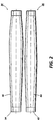
- the pressure roll 36 is crowned as is the fuser roll 34, as best seen in the enlarged elevational view of Figure 2.
- the pressure roll 36 is supported in pressure engagement with the fuser roll 34 as indicated by arrow 63 in Figure 1.
- the pressure roll 36 is crowned or larger in the center region of the roll than the ends to compensate for the bending of the fuser and pressure rolls, whereas the fuser roll 34 is crowned at an offset region to again account for the bending.
- the amount of radial increase (crown) is the sum of the defection of the fuser roll and pressure roll combination.
- the fuser roll stiffness is relatively unimportant so it can be made relatively thin and light so it warms up fast and is relatively inexpensive in power usage and construction. In a two roll fuser, warm-up time is an outgrowth of the roll mass required for adequate stiffness.
- a sheet 82 ( Figure 1) with toner 81 thereon is advanced to and through the nip 65 to affix images carried by the sheet to the sheet.
- the image has been transferred to the sheet 82 at a transfer station D.
- the transfer station D includes a corona generating device 32 proximate a moving photoconductive surface 12 between which the sheet has been directed to transfer the toner thereto, as is common in electrophotographic printers.
- the sheet after passing through the nip 65, is directed toward an output tray 38 via reversing roll set 37 and associated guides or baffled surfaces.
- Stripper means 87 such as are well known in the art may be used to ensure separation of the sheet 82 from the fuser roll surface 56 after passing out of the nip.
- controller 100 controls all machine steps and functions described herein, as well as that of any and/or all apparatus and devices associated with the sheet handler, such as, for example, an electrophotographic printing machine.
- the fuser and pressure roll lengths are in the order of 10 to 36 inches (25.4 to 91.4cm)
- the fuser and pressure outer surfaces were 12 inches long (320 mm).
- the fuser roll wall thickness is approximately 0 2 inches (5.5mm) and has a diameter of approximately 1.3 inches (32.2mm) thereby providing a fairly low mass fuser roll capable of rapid warmup.
- the light weight fuser roll is about 10-20% as stiff as the steel pressure roll which has approximately 1.14 inches (28.5mm) diameter and a wall thickness of approximately 0.5 inches (12.7mm).
- the increase in diameter of the fuser roll from and to maximum diameter, for the roll of the embodiment reduced to practice should increase from end to maximum width in a range between approximately 0.004 and 0.060 inches (0.01 and 0.15 mm), and preferably, approximately 0.020 inches (.05 mm) (i.e. , in the preferred embodiment reduce to practice the surface of the fuser roll varies in diameter from approximately 1.3 inches to 1.32 inches (32.2 to 32.25 mm ).
- the diameter of the pressure roll increases from the ends to a maximum diameter in a range from between approximately 0.020 to 0.400 inches (0.05 to 1.0 mm) from end to maximum diameter with approximately 0.144 inches (0.36 mm) preferred (i.e., in the preferred embodiment reduce to practice the surface of the pressure roll varies in diameter from approximately 1.14 to 1.297 inches (28.5 mm to 28.86 mm)).
- This arrangement yields a substantially uniform sheet velocity profile for sheets passing through the nip.
- the velocity profile for such sheets is such that it increases only approximately 0.5% from the center of the rolls to edges of the rolls Further, the arrangement also provides a relatively uniform nip pressure. It will be appreciated by those skilled in the art that the increase in velocity at the edges of sheets to be fused is actually a desirable condition. That is, it is enough of an increase to prevent creasing and yet not so much as to induce buckling of sheets, generally.
- the offset of the increase in diameter of the fuser roll to the increase in diameter of the pressure roll compensates for the fact that sheets are intended to pass along a registration edge when entering the nip. It will be understood by those skilled in the art that in a fuser assembly where the sheets are centrally fed relative to the rolls the maximum diameter of both rolls would be in the central region.
- the pressure roll be crowned at its center (e.g., approximately 5.8 inches (149mm) from the registration edge along which sheets are fed to the fuser apparatus) and that the fuser roll is crowned at a distance approximately between approximately 6.75 and 9 inches (180 and 240mm) with the preferred distance being approximately 6.3 inches (160mm) from the registration edge.
- the nip which is formed varies in size from approximately 0.175 inches (4.44 mm) proximate the registration edge to about 0.1650 inches (4.19mm) at the center to about .1800 inches (4.57mm) proximate the far edge (in this embodiment approximately 279.5 mm, 11 in.).
- the normal force or sheets in the nip varies from about 21.5 lbs./in. (3.76 N/mm) proximate the registration edge to about 17.25 lbs./in. (3.02 N/mm) at the center to about .23 lbs./in. (4.03 n/mm) proximate the far edge.
- a fuser roll having a maximum diameter positioned approximately one third of the length thereof
- the fuser roll engages a pressure roll having a maximum diameter at the center thereof.
- relatively narrow sheet e.g., A-5 short-edge feed
- larger sheet e.g., A-4 short-edge feed
- the fuser roll and pressure roll are crowned in a barrel or convex shape.
- One of the rolls either a pressure roll or a heated fuser roll (preferably the pressure roll)
- the other is crowned along its length but is larger at a region disposed away from the central region.
- the stiffness of the pressure roll and fuser roll is relatively unimportant so each can be made thin and light allowing for greater cost and performance flexibility. This is particularly true in a two roll fuser as warm-up time is an outgrowth of the roll mass required for adequate stiffness, and cost is generally an outgrowth of roll mass.
- the load i.e., the normal force
- the tangential velocity of the rolls, across their length, is different since the rolls vary in diameter along their lengths. This results in the surface speed varying due to the different radial dimensions of the rolls.
- the fuser roll and pressure roll nip provides a relatively constant speed profile for sheets because the deflection strain is uniform and the effective circumference formed by the rolls in the nip region is substantially uniform
- the speed profile of a sheet in the nip thus, is substantially constant across the sheet.
- a slight sheet speed profile increase from center to the edges of approximately .5% is contemplated and beneficial.
- the total size and weight of a fuser is usually an important consideration in design, and the lesser weight and smaller size with increased performance provided hereby are useful.
Landscapes
- Physics & Mathematics (AREA)
- General Physics & Mathematics (AREA)
- Fixing For Electrophotography (AREA)
- Rolls And Other Rotary Bodies (AREA)
Applications Claiming Priority (2)
| Application Number | Priority Date | Filing Date | Title |
|---|---|---|---|
| US343 | 1993-01-04 | ||
| US08/000,343 US5319430A (en) | 1993-01-04 | 1993-01-04 | Fuser mechanism having crowned rolls |
Publications (3)
| Publication Number | Publication Date |
|---|---|
| EP0606143A2 true EP0606143A2 (de) | 1994-07-13 |
| EP0606143A3 EP0606143A3 (de) | 1995-02-15 |
| EP0606143B1 EP0606143B1 (de) | 1998-05-06 |
Family
ID=21691101
Family Applications (1)
| Application Number | Title | Priority Date | Filing Date |
|---|---|---|---|
| EP94300021A Expired - Lifetime EP0606143B1 (de) | 1993-01-04 | 1994-01-04 | Fixiermechanismus mit balligen Walzen |
Country Status (4)
| Country | Link |
|---|---|
| US (1) | US5319430A (de) |
| EP (1) | EP0606143B1 (de) |
| JP (1) | JP3294698B2 (de) |
| DE (1) | DE69409974T2 (de) |
Cited By (1)
| Publication number | Priority date | Publication date | Assignee | Title |
|---|---|---|---|---|
| EP1146402A3 (de) * | 1995-12-14 | 2004-12-01 | Sharp Kabushiki Kaisha | Fixiervorrichtung |
Families Citing this family (33)
| Publication number | Priority date | Publication date | Assignee | Title |
|---|---|---|---|---|
| US5378525A (en) * | 1992-07-23 | 1995-01-03 | Tokai Rubber Industries, Ltd. | Crowned resilient roll with coating layer and method of producing the same |
| US5319430A (en) * | 1993-01-04 | 1994-06-07 | Xerox Corporation | Fuser mechanism having crowned rolls |
| US5546175A (en) * | 1995-09-13 | 1996-08-13 | Fuji Xerox Co., Ltd. | Image fixing device and method thereof |
| US5728252A (en) * | 1995-09-19 | 1998-03-17 | Polaroid Corporation | Method and apparatus for laminating image-bearing media |
| EP0864940A1 (de) * | 1997-03-14 | 1998-09-16 | Agfa-Gevaert N.V. | Wärme- und Druckschmelzfixiervorrichtung |
| US5953039A (en) * | 1997-11-24 | 1999-09-14 | Eastman Kodak Company | Photothermographic drum processor using low heat conductivity and low heat capacitance rollers |
| JP4106170B2 (ja) * | 1999-04-22 | 2008-06-25 | シンジーテック株式会社 | 画像形成装置に使用されるオイル塗布ローラ |
| US6206994B1 (en) | 1999-07-28 | 2001-03-27 | Advanced Materials Corporation | Method and apparatus for covering a metal roll core with a polymeric material preferable a high performance thermoplastic material |
| US6793754B1 (en) | 1999-07-28 | 2004-09-21 | Advanced Materials Corporation | Covered roll having an under-layer formed of resin infused densely packed fibers that provides increased strength and adhesion properties |
| US6776744B1 (en) | 1999-07-28 | 2004-08-17 | Advanced Materials Corporation | Method for and devices used in covering a roll core with a resin infused fiber reinforced adhesive under layer and a polymeric top layer, the method including the use of an improved mold tape |
| US6160982A (en) * | 1999-10-04 | 2000-12-12 | Xerox Corporation | Copy sheet distortion-removing fusing apparatus |
| JP3588646B2 (ja) * | 2000-09-28 | 2004-11-17 | 住友ゴム工業株式会社 | ゴルフボールのコアとカバーとを分離する方法 |
| US20040154146A1 (en) * | 2001-05-17 | 2004-08-12 | Pruitt Paul R. | Web spreader roll and methods for spreading webs of material |
| JP4628644B2 (ja) * | 2001-10-04 | 2011-02-09 | 富士通セミコンダクター株式会社 | 半導体装置の製造方法 |
| JP3817482B2 (ja) * | 2002-02-01 | 2006-09-06 | キヤノン株式会社 | 加熱装置および画像形成装置 |
| US6810229B2 (en) * | 2002-12-30 | 2004-10-26 | Lexmark International, Inc. | Non-contact fusing roller/media separation apparatus and method for its use |
| US7055946B2 (en) * | 2003-06-12 | 2006-06-06 | Lexmark International, Inc. | Apparatus and method for printing with an inkjet drum |
| JP4722494B2 (ja) * | 2004-02-25 | 2011-07-13 | 株式会社沖データ | 定着装置 |
| GB0406626D0 (en) * | 2004-03-24 | 2004-04-28 | Supreme Plastics Holdings Ltd | Application of zipper lengths to a web |
| US20060088350A1 (en) * | 2004-10-26 | 2006-04-27 | Kabushiki Kaisha Toshiba | Fixing device in image forming apparatus with pressing roller having a reversed crown shape |
| JP4207893B2 (ja) | 2004-12-28 | 2009-01-14 | ブラザー工業株式会社 | ベルトユニットおよび画像形成装置 |
| US7546800B2 (en) * | 2005-02-09 | 2009-06-16 | Spellbinders Paper Arts Co. Llc | Roller press for embellishing sheet media |
| US20060243593A1 (en) * | 2005-04-29 | 2006-11-02 | Bowman Kenneth A | Apparatus and method for improving contact between a web and a roll |
| US7870949B2 (en) * | 2005-07-13 | 2011-01-18 | Van Der Graaf Inc. | Method for bonding a coating on a roller |
| JP2007121444A (ja) * | 2005-10-25 | 2007-05-17 | Bridgestone Corp | 導電性ローラ |
| US7343131B2 (en) * | 2005-10-26 | 2008-03-11 | Kyocera Mita Corporation | Fixing device having a pressure roller and image forming device equipped with the same |
| JP2008158447A (ja) * | 2006-12-26 | 2008-07-10 | Fuji Xerox Co Ltd | 定着部材、定着装置および画像形成装置 |
| US8393266B2 (en) * | 2009-07-20 | 2013-03-12 | Lifestyle Crafts, Llc | Systems and methods applying a design on a medium |
| JP5928052B2 (ja) * | 2012-03-23 | 2016-06-01 | 富士ゼロックス株式会社 | 定着装置および画像形成装置 |
| US8833895B2 (en) | 2012-05-04 | 2014-09-16 | Xerox Corporation | Transfix roller with adaptive center loading for use in an indirect printer |
| JP5558618B1 (ja) | 2013-10-09 | 2014-07-23 | サトーホールディングス株式会社 | 弾性体ローラー |
| JP2017116638A (ja) * | 2015-12-22 | 2017-06-29 | 富士ゼロックス株式会社 | 定着装置及び画像形成装置 |
| JP6597550B2 (ja) * | 2016-10-21 | 2019-10-30 | 京セラドキュメントソリューションズ株式会社 | 定着装置及び画像形成装置 |
Family Cites Families (24)
| Publication number | Priority date | Publication date | Assignee | Title |
|---|---|---|---|---|
| US2732591A (en) * | 1956-01-31 | whittum | ||
| US1875257A (en) * | 1929-11-20 | 1932-08-30 | John A Nylund | Tapered feed roller |
| US2191144A (en) * | 1937-12-31 | 1940-02-20 | Beloit Iron Works | Press roll |
| BE546538A (de) * | 1955-04-12 | |||
| US3437032A (en) * | 1965-07-01 | 1969-04-08 | Xerox Corp | Heated fuser roll |
| US3884623A (en) * | 1973-02-16 | 1975-05-20 | Dyk Research Corp Van | Xerographic fuser roller |
| US3941558A (en) * | 1974-02-18 | 1976-03-02 | Rank Xerox Ltd. | Contact-heating fixing device for electrophotography |
| JPS5492747A (en) * | 1977-12-29 | 1979-07-23 | Minolta Camera Co Ltd | Pressure fixing device of powder lmages |
| US4214549A (en) * | 1978-06-28 | 1980-07-29 | Xerox Corporation | Roll fuser apparatus and release agent metering system therefor |
| JPS6018243B2 (ja) * | 1980-07-07 | 1985-05-09 | 株式会社日立製作所 | 圧延ロ−ル |
| JPS57184173A (en) * | 1981-05-02 | 1982-11-12 | Hori Glass Co Ltd | Holder of window glass holder for vehicle |
| US4393804A (en) * | 1981-11-12 | 1983-07-19 | Minnesota Mining And Manufacturing Company | Apparatus for removing toner from and applying offset preventive liquid to a fixing roller |
| US4557588A (en) * | 1982-05-21 | 1985-12-10 | Canon Kabushiki Kaisha | Image forming apparatus having a cleaning member |
| DE3323067A1 (de) * | 1983-06-27 | 1985-01-03 | Hoechst Ag, 6230 Frankfurt | Walzenfixiervorrichtung mit einer andruckwalze und einer von innen beheizten fixierwalze |
| JPS60227905A (ja) * | 1984-04-25 | 1985-11-13 | Matsushita Electric Works Ltd | 圧延用テ−パクラウンロ−ル |
| US4624921A (en) * | 1984-04-26 | 1986-11-25 | Cetus Corporation | Human lymphoblastold cell line and hybridomas derived therefrom |
| US4727392A (en) * | 1985-05-13 | 1988-02-23 | The Mead Corporation | Pressure development apparatus for imaging sheets employing photosensitive microcapsules |
| DE3620197A1 (de) * | 1986-06-16 | 1987-12-17 | Schloemann Siemag Ag | Walzwerk zur herstellung eines walzgutes, insbesondere eines walzbandes |
| US4812873A (en) * | 1986-09-09 | 1989-03-14 | Minolta Camera Kabushiki Kaisha | Heat fixing unit in an electrophotographic copying apparatus |
| JP2509544B2 (ja) * | 1987-08-07 | 1996-06-19 | キヤノン株式会社 | 弾性回転体及びそれを有する定着装置 |
| US4939552A (en) * | 1987-08-31 | 1990-07-03 | Minolta Camera Kabushiki Kaisha | Copying apparatus with drum or fixing roller cleaning belt driven from document scanner |
| US5045890A (en) * | 1989-04-07 | 1991-09-03 | Xerox Corporation | Fuser apparatus with release agent delivery system |
| US5049944A (en) * | 1989-04-07 | 1991-09-17 | Xerox Corporation | Method and apparatus for controlling the application of a fuser release agent |
| US5319430A (en) * | 1993-01-04 | 1994-06-07 | Xerox Corporation | Fuser mechanism having crowned rolls |
-
1993
- 1993-01-04 US US08/000,343 patent/US5319430A/en not_active Expired - Fee Related
- 1993-12-28 JP JP33669793A patent/JP3294698B2/ja not_active Expired - Fee Related
-
1994
- 1994-01-04 DE DE69409974T patent/DE69409974T2/de not_active Expired - Fee Related
- 1994-01-04 EP EP94300021A patent/EP0606143B1/de not_active Expired - Lifetime
Cited By (1)
| Publication number | Priority date | Publication date | Assignee | Title |
|---|---|---|---|---|
| EP1146402A3 (de) * | 1995-12-14 | 2004-12-01 | Sharp Kabushiki Kaisha | Fixiervorrichtung |
Also Published As
| Publication number | Publication date |
|---|---|
| JPH06236123A (ja) | 1994-08-23 |
| EP0606143B1 (de) | 1998-05-06 |
| DE69409974D1 (de) | 1998-06-10 |
| EP0606143A3 (de) | 1995-02-15 |
| DE69409974T2 (de) | 1998-11-05 |
| JP3294698B2 (ja) | 2002-06-24 |
| US5319430A (en) | 1994-06-07 |
Similar Documents
| Publication | Publication Date | Title |
|---|---|---|
| EP0606143B1 (de) | Fixiermechanismus mit balligen Walzen | |
| JP3282494B2 (ja) | 画像定着装置 | |
| US9377725B2 (en) | Fixing device and image forming apparatus incorporating same | |
| US9116494B2 (en) | Fixing device having a fuser pad of varying thickness and image forming apparatus incorporating same | |
| EP1762910B1 (de) | Erwärmungsvorrichtung für ein Tonerbild | |
| JP3298354B2 (ja) | 画像定着装置 | |
| US6636718B2 (en) | Heating roller, method of producing the heating roller, and heating device, fixing device and image forming apparatus using the heating roller | |
| JP5464902B2 (ja) | 定着装置 | |
| EP0635767B1 (de) | Fixiervorrichtung | |
| JP2002207389A (ja) | 画像定着装置 | |
| JPH103231A (ja) | 一様なニップ速度のロール定着装置 | |
| JPH103230A (ja) | 一様なニップ速度のロール定着装置 | |
| JP3478068B2 (ja) | 定着装置 | |
| US5209997A (en) | Three roll fuser | |
| US5420678A (en) | Pinch roll for a release material delivery system | |
| EP2353049A1 (de) | Extern geheizte fixiereinrichtung mit erweiterter nip-breite | |
| US20050163542A1 (en) | Backup belt assembly for use in a fusing system and fusing systems therewith | |
| JPH11202666A (ja) | 定着装置 | |
| US7260353B2 (en) | Image heating apparatus with heating nip for preventing image failure | |
| JPH06118817A (ja) | 加熱装置 | |
| US5671473A (en) | Fusing device, a heating device, and a method for fusing a toner image onto a sheet | |
| JP2020118785A (ja) | 画像形成装置 | |
| JP2004279857A (ja) | 加熱定着装置および画像形成装置 | |
| JP2009271441A (ja) | 画像加熱装置 | |
| JPH09281824A (ja) | ベルト定着装置 |
Legal Events
| Date | Code | Title | Description |
|---|---|---|---|
| PUAI | Public reference made under article 153(3) epc to a published international application that has entered the european phase |
Free format text: ORIGINAL CODE: 0009012 |
|
| AK | Designated contracting states |
Kind code of ref document: A2 Designated state(s): DE FR GB |
|
| PUAL | Search report despatched |
Free format text: ORIGINAL CODE: 0009013 |
|
| AK | Designated contracting states |
Kind code of ref document: A3 Designated state(s): DE FR GB |
|
| 17P | Request for examination filed |
Effective date: 19950816 |
|
| 17Q | First examination report despatched |
Effective date: 19961210 |
|
| GRAG | Despatch of communication of intention to grant |
Free format text: ORIGINAL CODE: EPIDOS AGRA |
|
| GRAG | Despatch of communication of intention to grant |
Free format text: ORIGINAL CODE: EPIDOS AGRA |
|
| GRAH | Despatch of communication of intention to grant a patent |
Free format text: ORIGINAL CODE: EPIDOS IGRA |
|
| GRAH | Despatch of communication of intention to grant a patent |
Free format text: ORIGINAL CODE: EPIDOS IGRA |
|
| GRAA | (expected) grant |
Free format text: ORIGINAL CODE: 0009210 |
|
| AK | Designated contracting states |
Kind code of ref document: B1 Designated state(s): DE FR GB |
|
| REF | Corresponds to: |
Ref document number: 69409974 Country of ref document: DE Date of ref document: 19980610 |
|
| ET | Fr: translation filed | ||
| PLBE | No opposition filed within time limit |
Free format text: ORIGINAL CODE: 0009261 |
|
| STAA | Information on the status of an ep patent application or granted ep patent |
Free format text: STATUS: NO OPPOSITION FILED WITHIN TIME LIMIT |
|
| 26N | No opposition filed | ||
| REG | Reference to a national code |
Ref country code: GB Ref legal event code: IF02 |
|
| REG | Reference to a national code |
Ref country code: GB Ref legal event code: 746 Effective date: 20041130 |
|
| PGFP | Annual fee paid to national office [announced via postgrant information from national office to epo] |
Ref country code: GB Payment date: 20041229 Year of fee payment: 12 |
|
| PGFP | Annual fee paid to national office [announced via postgrant information from national office to epo] |
Ref country code: DE Payment date: 20041231 Year of fee payment: 12 |
|
| PGFP | Annual fee paid to national office [announced via postgrant information from national office to epo] |
Ref country code: FR Payment date: 20050110 Year of fee payment: 12 |
|
| REG | Reference to a national code |
Ref country code: FR Ref legal event code: D6 |
|
| PG25 | Lapsed in a contracting state [announced via postgrant information from national office to epo] |
Ref country code: GB Free format text: LAPSE BECAUSE OF NON-PAYMENT OF DUE FEES Effective date: 20060104 |
|
| PG25 | Lapsed in a contracting state [announced via postgrant information from national office to epo] |
Ref country code: FR Free format text: LAPSE BECAUSE OF NON-PAYMENT OF DUE FEES Effective date: 20060131 |
|
| PG25 | Lapsed in a contracting state [announced via postgrant information from national office to epo] |
Ref country code: DE Free format text: LAPSE BECAUSE OF NON-PAYMENT OF DUE FEES Effective date: 20060801 |
|
| GBPC | Gb: european patent ceased through non-payment of renewal fee |
Effective date: 20060104 |
|
| REG | Reference to a national code |
Ref country code: FR Ref legal event code: ST Effective date: 20060929 |