EP0606593A2 - Photocopieur - Google Patents
Photocopieur Download PDFInfo
- Publication number
- EP0606593A2 EP0606593A2 EP93119986A EP93119986A EP0606593A2 EP 0606593 A2 EP0606593 A2 EP 0606593A2 EP 93119986 A EP93119986 A EP 93119986A EP 93119986 A EP93119986 A EP 93119986A EP 0606593 A2 EP0606593 A2 EP 0606593A2
- Authority
- EP
- European Patent Office
- Prior art keywords
- page number
- copying
- image
- recognizing
- page
- Prior art date
- Legal status (The legal status is an assumption and is not a legal conclusion. Google has not performed a legal analysis and makes no representation as to the accuracy of the status listed.)
- Granted
Links
Images















Classifications
-
- H—ELECTRICITY
- H04—ELECTRIC COMMUNICATION TECHNIQUE
- H04N—PICTORIAL COMMUNICATION, e.g. TELEVISION
- H04N1/00—Scanning, transmission or reproduction of documents or the like, e.g. facsimile transmission; Details thereof
- H04N1/32—Circuits or arrangements for control or supervision between transmitter and receiver or between image input and image output device, e.g. between a still-image camera and its memory or between a still-image camera and a printer device
- H04N1/32358—Circuits or arrangements for control or supervision between transmitter and receiver or between image input and image output device, e.g. between a still-image camera and its memory or between a still-image camera and a printer device using picture signal storage, e.g. at transmitter
- H04N1/3248—Storage of at least a part of one of two image bearing sides of a single sheet, e.g. for two sided copying
-
- G—PHYSICS
- G03—PHOTOGRAPHY; CINEMATOGRAPHY; ANALOGOUS TECHNIQUES USING WAVES OTHER THAN OPTICAL WAVES; ELECTROGRAPHY; HOLOGRAPHY
- G03G—ELECTROGRAPHY; ELECTROPHOTOGRAPHY; MAGNETOGRAPHY
- G03G15/00—Apparatus for electrographic processes using a charge pattern
- G03G15/22—Apparatus for electrographic processes using a charge pattern involving the combination of more than one step according to groups G03G13/02 - G03G13/20
- G03G15/23—Apparatus for electrographic processes using a charge pattern involving the combination of more than one step according to groups G03G13/02 - G03G13/20 specially adapted for copying both sides of an original or for copying on both sides of a recording or image-receiving material
- G03G15/231—Arrangements for copying on both sides of a recording or image-receiving material
-
- H—ELECTRICITY
- H04—ELECTRIC COMMUNICATION TECHNIQUE
- H04N—PICTORIAL COMMUNICATION, e.g. TELEVISION
- H04N1/00—Scanning, transmission or reproduction of documents or the like, e.g. facsimile transmission; Details thereof
- H04N1/32—Circuits or arrangements for control or supervision between transmitter and receiver or between image input and image output device, e.g. between a still-image camera and its memory or between a still-image camera and a printer device
- H04N1/32358—Circuits or arrangements for control or supervision between transmitter and receiver or between image input and image output device, e.g. between a still-image camera and its memory or between a still-image camera and a printer device using picture signal storage, e.g. at transmitter
- H04N1/32459—Circuits or arrangements for control or supervision between transmitter and receiver or between image input and image output device, e.g. between a still-image camera and its memory or between a still-image camera and a printer device using picture signal storage, e.g. at transmitter for changing the arrangement of the stored data
- H04N1/32464—Changing the arrangement of pages or documents, e.g. for producing pages to be bound
-
- H—ELECTRICITY
- H04—ELECTRIC COMMUNICATION TECHNIQUE
- H04N—PICTORIAL COMMUNICATION, e.g. TELEVISION
- H04N1/00—Scanning, transmission or reproduction of documents or the like, e.g. facsimile transmission; Details thereof
- H04N1/32—Circuits or arrangements for control or supervision between transmitter and receiver or between image input and image output device, e.g. between a still-image camera and its memory or between a still-image camera and a printer device
- H04N1/32561—Circuits or arrangements for control or supervision between transmitter and receiver or between image input and image output device, e.g. between a still-image camera and its memory or between a still-image camera and a printer device using a programmed control device, e.g. a microprocessor
-
- G—PHYSICS
- G03—PHOTOGRAPHY; CINEMATOGRAPHY; ANALOGOUS TECHNIQUES USING WAVES OTHER THAN OPTICAL WAVES; ELECTROGRAPHY; HOLOGRAPHY
- G03G—ELECTROGRAPHY; ELECTROPHOTOGRAPHY; MAGNETOGRAPHY
- G03G2215/00—Apparatus for electrophotographic processes
- G03G2215/00172—Apparatus for electrophotographic processes relative to the original handling
- G03G2215/00206—Original medium
- G03G2215/00282—Book
-
- G—PHYSICS
- G03—PHOTOGRAPHY; CINEMATOGRAPHY; ANALOGOUS TECHNIQUES USING WAVES OTHER THAN OPTICAL WAVES; ELECTROGRAPHY; HOLOGRAPHY
- G03G—ELECTROGRAPHY; ELECTROPHOTOGRAPHY; MAGNETOGRAPHY
- G03G2215/00—Apparatus for electrophotographic processes
- G03G2215/00172—Apparatus for electrophotographic processes relative to the original handling
- G03G2215/00206—Original medium
- G03G2215/00316—Electronic image supplied to the apparatus
-
- G—PHYSICS
- G03—PHOTOGRAPHY; CINEMATOGRAPHY; ANALOGOUS TECHNIQUES USING WAVES OTHER THAN OPTICAL WAVES; ELECTROGRAPHY; HOLOGRAPHY
- G03G—ELECTROGRAPHY; ELECTROPHOTOGRAPHY; MAGNETOGRAPHY
- G03G2215/00—Apparatus for electrophotographic processes
- G03G2215/00362—Apparatus for electrophotographic processes relating to the copy medium handling
- G03G2215/00535—Stable handling of copy medium
- G03G2215/00556—Control of copy medium feeding
- G03G2215/00586—Control of copy medium feeding duplex mode
-
- G—PHYSICS
- G03—PHOTOGRAPHY; CINEMATOGRAPHY; ANALOGOUS TECHNIQUES USING WAVES OTHER THAN OPTICAL WAVES; ELECTROGRAPHY; HOLOGRAPHY
- G03G—ELECTROGRAPHY; ELECTROPHOTOGRAPHY; MAGNETOGRAPHY
- G03G2215/00—Apparatus for electrophotographic processes
- G03G2215/00362—Apparatus for electrophotographic processes relating to the copy medium handling
- G03G2215/00535—Stable handling of copy medium
- G03G2215/00556—Control of copy medium feeding
- G03G2215/00594—Varying registration in order to produce special effect, e.g. binding margin
-
- G—PHYSICS
- G03—PHOTOGRAPHY; CINEMATOGRAPHY; ANALOGOUS TECHNIQUES USING WAVES OTHER THAN OPTICAL WAVES; ELECTROGRAPHY; HOLOGRAPHY
- G03G—ELECTROGRAPHY; ELECTROPHOTOGRAPHY; MAGNETOGRAPHY
- G03G2215/00—Apparatus for electrophotographic processes
- G03G2215/04—Arrangements for exposing and producing an image
- G03G2215/0402—Exposure devices
- G03G2215/0424—Using contents of CCD array to produce the image
-
- H—ELECTRICITY
- H04—ELECTRIC COMMUNICATION TECHNIQUE
- H04N—PICTORIAL COMMUNICATION, e.g. TELEVISION
- H04N2201/00—Indexing scheme relating to scanning, transmission or reproduction of documents or the like, and to details thereof
- H04N2201/0077—Types of the still picture apparatus
- H04N2201/0081—Image reader
-
- H—ELECTRICITY
- H04—ELECTRIC COMMUNICATION TECHNIQUE
- H04N—PICTORIAL COMMUNICATION, e.g. TELEVISION
- H04N2201/00—Indexing scheme relating to scanning, transmission or reproduction of documents or the like, and to details thereof
- H04N2201/0077—Types of the still picture apparatus
- H04N2201/0082—Image hardcopy reproducer
-
- H—ELECTRICITY
- H04—ELECTRIC COMMUNICATION TECHNIQUE
- H04N—PICTORIAL COMMUNICATION, e.g. TELEVISION
- H04N2201/00—Indexing scheme relating to scanning, transmission or reproduction of documents or the like, and to details thereof
- H04N2201/32—Circuits or arrangements for control or supervision between transmitter and receiver or between image input and image output device, e.g. between a still-image camera and its memory or between a still-image camera and a printer device
- H04N2201/3285—Circuits or arrangements for control or supervision between transmitter and receiver or between image input and image output device, e.g. between a still-image camera and its memory or between a still-image camera and a printer device using picture signal storage, e.g. at transmitter
- H04N2201/3287—Storage of at least one complete document page or image frame
-
- H—ELECTRICITY
- H04—ELECTRIC COMMUNICATION TECHNIQUE
- H04N—PICTORIAL COMMUNICATION, e.g. TELEVISION
- H04N2201/00—Indexing scheme relating to scanning, transmission or reproduction of documents or the like, and to details thereof
- H04N2201/32—Circuits or arrangements for control or supervision between transmitter and receiver or between image input and image output device, e.g. between a still-image camera and its memory or between a still-image camera and a printer device
- H04N2201/3285—Circuits or arrangements for control or supervision between transmitter and receiver or between image input and image output device, e.g. between a still-image camera and its memory or between a still-image camera and a printer device using picture signal storage, e.g. at transmitter
- H04N2201/3288—Storage of two or more complete document pages or image frames
Definitions
- the present invention relates to a copying machine and, more particularly, to a copying machine which is provided with a page number recognizing unit for recognizing the page number of an original document.
- Japanese publication of the examined application No. JP, B2, 60-26208 describes such a conventional two-sided copying machine which is capable of continuously illuminating two spread pages of a book or document and of copying the two pages on two separate sheets of paper respectively
- Both reference materials disclose nothing relating to a method for controlling the operations of a two-sided copying machine according to the results of the recognizing of page numbers on a document's image.
- Any conventional copying machine has the following drawbacks: When copying originals (e.g., a book) having respective page numbers on both sides of a sheet of paper with the same binding margin by using any conventional copying machine, an operator is required to specify the direction of the placement of the originals on the copying machine. Similarly, to get a copy having the same printed sides as the original, the operator must specify the order of copying or select one-sided copying for the first page of the documents. That may impair the efficiency of the machine's operation and easily cause mis-copying.
- originals e.g., a book
- any conventional copying machine When copying originals (e.g., a book) having respective page numbers on both sides of a sheet of paper with the same binding margin by using any conventional copying machine, an operator is required to specify the direction of the placement of the originals on the copying machine. Similarly, to get a copy having the same printed sides as the original, the operator must specify the order of copying or select one-sided copying for the first page
- each copy may have two page numbers - the page number copied from the original and the page number on the final draft. Such mixed numbering decreases the quality of the document.
- a book is usually edited to have the chapters, each of which starts from the right side leaving the left side blank if the preceding chapter ends at the right side. Consequently, the conventional copying machine may copy a blank page as long as the user is not aware of it. On the contrary, if such original pages are copied on both sides of the sheets of paper, omitting the blank pages, the copies cannot correctly correspond to the originals.
- the copying machine which possesses at least one function to erase the page number portion of an original image or to replace the page number of the original image by a page number to be determined according to the order of the copying done or to correct the page number according to the number on an image to be copied, may produce copy without printing the unnecessary page numbers.
- the copying machine may correct the page number of each original image according to the operator's instructions. This function can newly page the copies which then can be easily edited.
- the machine can automatically avoid copying a blank page of paper inserted between the last page of the current chapter and the page of the next chapter and can correct the paging of images to be copied on both sides of a sheet of paper, thereby assuring the correct continuity of copies. This function improves the reliability of the machine and prevents mis-copying.
- the machine when copying paged originals, the machine can always produce copies with the correct paging requiring no aid from the operator. It can also prevent double copying of the same page if the operator inadvertently places the original on the machine twice. It is capable of storing images without over-flowing at random copying of differently paged originals to assure the correct paging of copies and their easy editing. This function makes the machine easier to operate and increases the effectiveness of the operation with a minimum of waste.
- a book usually has at its spread a left-hand leaf paged with an even number and right-hand leaf paged with an odd number.
- the page number of the original image is recognized and an image shifting value is adjusted so that the same binding margin as that of the left-hand and right-hand pages of a book may be provided at correct positions on respective copies.
- the read-in original images can be temporarily stored so that both sides of a leaf of the book may be correctly copied on the respective sides of paper regardless of which page is first copied, i.e., the same perfected copy as the both-sided printed leaf of the book may be automatically obtained regardless of the order of copying .
- the present invention is intended to provide a copying machine which is capable of: controlling the binding, margin preparation at two-sided copying according to the result of the recognition of a page's number in an original document; controlling relationships between the front side and the back side of a sheet of paper in two-sided copying according to the result of recognizing a page number on an original document; erasing or correcting a page number on an image according to the result of recognizing a page number's position or a page number on a document; generating an alarm when failing to recognize a page number on a document to be copied; recognizing the existence or absence of a page number on a document to be copied and of copying a numberless page at the top or the reverse side of a sheet of paper when copying both sides of it; changing at least either the order for putting out an image to be copied or the path for delivering the copy according to the recognition of the page number on a document's image.
- Fig. 1 is a sectional view for explaining an example of a copying machine embodied in the present invention.
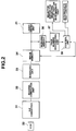
- Fig. 2 is a block diagram for explaining the image processing portion of a copying machine of the present invention defined in claims 1 and 2.
- Fig. 3 is a block diagram for explaining the image processing portion of a copying machine of the present invention defined in claim 3.
- Fig. 4 is a block diagram for explaining the image processing portion of a copying machine of the present invention defined in claims 4 and 5.
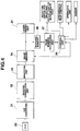
- Fig. 5 is a block diagram for explaining the image processing portion of a copying machine of the present invention defined in claims 6 and 9.
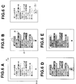
- Fig. 6 is a view for explaining the operations of a page number recognizing unit.
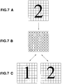
- Fig. 7 is a view for explaining an example of the method for recognizing a page number.
- Fig. 8 is a flow chart showing a part of the procedure for recognizing a page number.
- Fig. 9 is a flow chart showing a part of the procedure for recognizing a page number.
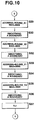
- Fig. 10 is a flow chart showing a part of the procedure for recognizing a page number.
- Fig. 11 is a flow chart showing a part of the procedure for recognizing a page number.
- Fig. 12 is a flow chart showing a part of the procedure for recognizing a page number.
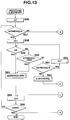
- Fig. 13 is a flow chart showing a part of the procedure for boundary smoothing.
- Fig. 14 is a flow chart showing a part of the procedure for boundary smoothing.
- Fig. 15 is a flow chart showing a part of the procedure for detecting a minimal value of black pixels.
- Fig. 16 is a flow chart showing a part of the procedure for detecting a minimal value of black pixels.
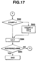
- Fig. 17 is a flow chart showing a part of the procedure for detecting a minimal value of black pixels.
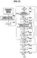
- Fig. 18 is a flow chart showing a part of the procedure for determining the position of a page number according to an isolated portion of black pixels.
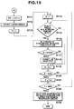
- Fig. 19 is a flow chart showing a part of the procedure for determining the position of a page number according to an isolated portion of black pixels.
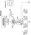
- Fig. 20 is a flow chart showing a part of the procedure for determining the peripheral length of a black pixel portion, including a certain point of coordinates.
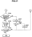
- Fig. 21 is a flow chart showing a part of the procedure for determining the peripheral length of black pixels' portion including a certain point of coordinates.
- Fig. 22 is a flow chart showing a part of the procedure for processing one digit of a page number by a page number recognizing method.
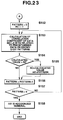
- Fig. 23 is a flow chart showing a part of the procedure for processing one digit of a page number by a page number recognizing method.
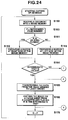
- Fig. 24 is a flow chart showing a part of an explanation on operations (for controlling a binding margin and the top and reverse sides of a sheet of paper to be printed on (both sides) of the present invention as defined in claims 1 and 2.
- Fig. 25 is a flow chart showing a part of an explanation on operations (for controlling a binding margin and front and back sides of paper to be printed on (both sides) of the present invention, as defined in claims 1 and 2.
- Fig. 26 is a flow chart showing a part of an explanation on operations (for erasing or replacing a page number) of the present invention as defined in claim 3.
- Fig. 27 is a flow chart showing a part of an explanation on operations (for erasing or replacing a page number) of the present invention as defined in claim 3.
- Fig. 28 is a flow chart for explaining operations (for erasing or modifying a page number) of the present invention as defined in claim 3.
- Fig. 29 is a flow chart showing a part of an explanation on operations (for detecting whether a page number exists or not and for processing according to the detection result) of the present invention as defined in claims 4 and 5.
- Fig. 30 is a flow chart showing a part of an explanation on operations (for detecting whether a page number exists or not and for processing according to the detection result) of the present invention as defined in claims 4 and 5.
- Fig. 31 is a flow chart showing a part of the procedure (for changing the order of the output of original copies having page numbers according to the result of page number recognition) of the present invention as defined in claims 6 and 9.
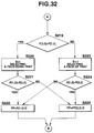
- Fig. 32 is a flow chart showing a part of the procedure (for changing the order of the output of original copies having page numbers according to the result of page number recognition) of the present invention as defined in claims 6 and 9.
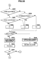
- Fig. 33 is a flow chart showing a part of the procedure (for changing the order of the output of original copies having page numbers according to a result of page number recognition) of the present invention as defined in claims 6 and 9.
- Fig. 34 is a flow chart showing a part of the procedure (for changing the order of the output of original copies having page numbers according to the result of page number recognition) of the present invention as defined in claims 6 and 9.
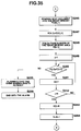
- Fig. 35 is a flow chart showing a part of the procedure (for changing the order of the output of original copies having page numbers according to the result of page number recognition) of the present invention as defined in claims 6 and 9.
- Fig. 36 is a view showing an example of a construction of an editor for allowing an operator to input data on a page number position.
- Fig. 37 is a view showing an example of a control panel for the present invention as defined in claim 3.
- Fig. 38 is a view showing an example of a control panel of the present invention as defined in claims 4 and 5.
- Fig. 39 is a view showing an example of a control panel of the present invention as defined in claims 4 to 9.
- Fig. 1 is a sectional view for explaining an example of a digital copying machine embodied in the present invention.
- the copying machine has a body 1 and a document feeding device 2 for automatically transferring an original 4 from a document feeding tray 3 to a specified position 5 where the original is subjected to exposure.
- the automatic document feeding device 2 is used in the case of copying a separate sheet of an original 4.
- the exposure lamp 6 illuminates an original 7
- the reflected light from the original 7 is reflected on a mirror 8 then passes through a lens 9 and enters into a CCD sensor 22 by which it is converted into electrical signals.
- Image data taken through the CCD sensor 22 is processed by an image processor shown in Fig. 2 and then fed to a laser driver 21 which generates a laser light which is ON-OFF controlled according to the received image data,
- the laser light is directed by the means of a mirror 23 to a light-sensitive drum 11 which is being rotatable in the direction shown by the arrow A. Since the light-sensitive drum 11 is evenly charged before being exposed to the laser light by the charging device 10 placed at the up-stream side of the drum rotating direction, relative to the exposed position of the drum, an electrostatic latent image is formed on the electrically charged surface of the light-sensitive drum 11 by the action of the laser light.
- the latent image formed on the light-sensitive drum 11 is developed with the use of toner 14 fed from a developing container 13 to form a toner image which is then transferred by the copying unit 17 to a sheet of paper 16 fed from a paper cassette 15 and fixed thereon by a fixing unit 19.
- the sheet of paper printed on one side is delivered to a face-up tray 25 or a face-down tray 26. Toner, remaining on the light-sensitive drum 11, is cleared off by a cleaning unit 20.
- Figs. 2 to 5 are block diagrams for explaining examples of respective image processing portions of copying machines embodied in the present invention.
- Original image data read-in through a CCD sensor 22 are converted on an A-D converter 31 into digital signals which are corrected by a shading correction unit 32, binarized by a binarizing unit 33 and stored in an image memory 34.
- a page number recognizing unit 37 reads a page number printed on the original from its image data stored in the image memory 34 using a working memory 36 for image data that is connected to the page number recognizing unit 37 for the page number recognizing process.
- the image data stored in the image memory 34 is transferred to a laser driver unit 21 to be further exposed to laser light.
- a control unit 38 checks the page number and provides a binding margin at a suitable position on the stored image. In the case shown a binding margin of about 20 mm is provided. Furthermore, the control unit 38 decides whether a sheet is to be printed on one side or both according to the page number recognized.
- the page number recognizing unit 37 reads the page number printed on the original from its image data stored in the image memory 34 by using the working memory 36 that is connected to the page number recognizing unit 37 for the page number recognizing process.
- the image data stored in the image memory 34 is transferred to a laser driver unit 21 to be further exposed to laser light.
- a page image processing unit 39 performs the processing(erasing-correcting) of the page number portion of the image memory 34 according to the recognition made by the page number recognizing unit 37.
- a control unit 38 performs checking for the presence or absence of a page number by generating an alarm signal by a buzzer and the decision for copying on the front or the back side of a sheet of paper on the basis of the page number recognizing result.
- the image memory 34 has three memory units 34a, 34b and 34c for temporarily storing three separate pages of images in order to realize the function for changing the order of producing them.
- An image selector switch 41 provided between the binarizing unit 33 and the image memory 34 (memory units 34a, 34b and 34c) actuates to select one of the three image memory units according to the instructions from an input/output control unit.
- a page number recognizing unit 37 reads the page number printed on the original from its image data stored in the image memory 34 using the working memory 36 that is connected to the page number recognizing unit 37 for page number recognizing processing.
- the page numbers read out of the image data are arranged in the format shown in table 1 and stored in the page number memory 43 which is composed of a random access memory chip allowing access from the page number recognizing unit 37 and the input/output control unit 44.
- the input/output control unit 44 checks the page number and selects a suitable image memory.
- a delivery path selector switch 47 is preset to deliver the copies toward a face-down receiving tray 26 as shown in Fig. 1.
- the delivery path selector switch 47 is preset to direct copies toward the face-up receiving tray 25 as shown in Fig. 1.
- the image data from the selected image memory units 34a, 34b and 34c are sent to a laser driver unit 21 which transfers the image by laser light to an electrically charged rotating light-sensitive drum 11.
- the input/output control unit 44 turns the buzzer ON 46 for coursing on alarm when the result for checking on page numbers indicates that the two images having the same page number are stored in the image memory units 34a, 34b and 34c or the operator tries inputting the next original in spite of the absence of a vacant image memory.
- the number "n" of an original indicates that the original was read in the n-th place after starting the work of copying.
- Table 1 shows an example of a memory format of the page number memory 43 which comprises of memory units.
- the number in the left column "Original No.” means the original number that was scanned.
- the numbers of image memory units in which respectively scanned images are stored In the middle column of table 1 are shown the numbers of image memory units in which respectively scanned images are stored and in the right column are shown recognized page numbers of the originals.
- table 1 contains originals No.'s 1 to 9, the practical image memory has enough capacity to process and store the images to be copied.
- Figs. 6A to 6E illustrate the steps for processing the page number recognizing unit.
- the page number recognizing unit determines an area containing black pixels on an original image and recognizes the digit pattern in a specified convex portion of the area or the isolated portion of black pixels as the original's page number. Since image data read in through a CCD sensor 22 is binarized, the image data stored in the image memory are subjected at first to smoothing to remove small separate black pixels produced by the effect of noises before processing (Fig. 6A). Since the background of the original document is usually blank, an area occupied by black pixels on the original image is determined and, at the same time, it is filled with black pixels and its boundary is smoothed to obtain the pattern shown in Fig. 6B.
- Figs. 6C to 6E illustrate how to specify the location of a page number on an image after the processing step of Fig. 6B.
- a digit pattern in the selected convex or isolated portion is recognized as the page number of the original image. Since a digit pattern of the page number for each original image may be included in an area of a constant size, a mask 51 sized as shown in Fig.
- the mask 51 is supposed and placed onto each boundary of the black pixels' area in such a way that the boundary line of the area may pass the center of the mask 51. Black pixels included in the mask are then counted.
- the mask 51 covers a convex that is similar in size and has a top line laid onto the center line of the mask 51 as shown in Fig. 6D, it may contain a reduced number of black pixels. All boundary portions are checked with the mask 51 and a location (coordinates) at which the least number of black pixels is counted is determined as the center of the convex portion containing the page number.
- Fig. 6E illustrates the method for specifying the location of a page number by comparing the sizes of isolated (separate) lines of black pixels.
- each line is treated as an isolated block of black pixels, whose boundary (circumferential) length is measured by scanning from one point thereon. This operation is repeated on all isolated blocks.
- An isolated black block of the least circumferential length is determined as containing the page number.
- Fig. 7A to 7C are a view for explaining how to recognize numerals (page number) in the portion determined by the steps of Fig. 6.
- the page number is recognized digit by digit.
- An area which substantially corresponds in size to a page number block usually used in a book is evenly divided into 64 (8 x 8) blocks as shown in Fig. 7A, and a ratio of black pixels' existence in each block is calculated as shown in Fig. 7B.
- the result of the calculation is compared with the data preliminarily obtained by calculating on typical digit patterns.
- a numeral whose known digit pattern (as shown in Fig.7C; right side) mostly correlates with the calculation result is found to be the page number or one element thereof (Fig. 7C).
- Fig. 8 to Fig. 12 are flow charts showing the procedure for the processing of Figs. 6A to 6D.
- an image memory 34 and a working memory 36 have, respectively, 3500 pixels in an X-direction and 4800 pixels in a Y-direction (Fig. 6A) and allows for writing therein the image at a resolution of 16 pixels per millimeter.
- the image data stored in the image memory 34 is copied into the working memory 36 (Step 1 of Fig. 8).
- the smoothing process is performed to remove noises (Step 2 of Fig. 8).
- Arrays BOUND_X1 and BOUND_X2 for memorizing the positions of the boundary lines of portions A and B, respectively, of Fig. 6B are all cleared to 0 (Step 3).
- Arrays BOUND_X1,_X2 have a size of 4800 pixels corresponding to the size of the pixels in the Y-direction.
- Variables X and Y of the coordinates in the working memory 36 are assumed as 1 (Step 4 and step 5). Image scanning is performed to distinguish the boundary line.
- Coordinate X is replaced by Y and a similar process is executed on BOUND_Y1[X], BOUND_Y2[X] (Step 16 to Step 28 of Fig. 9).
- BOUND_Y1 and BOUND_Y2 are arrays for memorizing positions of boundary lines of portions C and D, respectively, of Fig. 6B. Each array has a size of 3500 pixels corresponding to the size of the pixel in an X-direction.
- Figs. 13 and 14 are flow charts for explaining a smoothing procedure commonly applied to BOUND_X1,_X2, _Y1,_Y2 (to be referred to by addresses). Basically, an arithmetical mean is calculated from the coordinate values of a currently remarked position and a position shifted by 1 pixel in the positive direction.
- a variable "i" representing a currently remarked (unidimentional) coordinate is initialized (Step 56 of Fig. 13) and ADDRESS[i] is checked. Since ADDRESS[i] is 0 for a line in which no black pixel is detected (Step 57 to Step 58), a coordinate being not equal to 0 is searched for in the negative direction from the remarked coordinate (Step 58 to Step 62, Step 63).
- Step 60 Since a point having the coordinate ⁇ 0 cannot be detected by further scanning when ADDRESS[i] is 9999, a value 9999 is placed therein (Step 60 ⁇ Step 64).
- Step 68 to Step 69 of Fig.14 scanning is performed in the positive direction when a remarked pixel is at 0 (Step 68 to Step 69 of Fig.14).
- the end mark is set (Step 70, Step 71 ⁇ Step 72).
- said coordinate value is set in the place "b" and the mean value is calculated (Step 77, Step 75 ⁇ Step 76). The above-mentioned procedure is repeated until "i" becomes the maximal value.
- each pixel (X, Y) is converted into black on condition that coordinate (X, Y) is: BOUND_X1[Y] ⁇ X ⁇ BOUND_X2[Y] and BOUND_Y1[X] ⁇ Y ⁇ BOUND_Y2[X] (Step 39 to Step 41 of Fig. 11).
- Figs. 15 to 17 commonly illustrate the procedure for processing the detection of the least number of black pixels for the arrays BOUND_X1 to BOUND_Y2.
- a numeral code 9999 is set at the end portion of BOUND_.
- the portion having ADDRESS[i] ⁇ 9999 is searched (Step 80 of Fig. 15).
- the image memory has a coordinate system in which ADDRESS[i] is the abscissa (x-axis) and i is the ordinate (y-axis), while in the case of dX ⁇ 0 it has a coordinate system in which ADDRESS[i] is the ordinate (y-axis) and i is the abscissa (x-axis) (Step 81 to Step 83 of Fig. 15).
- Step 84 to Step 91 of Figs. 15 and 16 the number of black pixels in a range of ⁇ 50 pixels with reference to the above-mentioned coordinates is counted (Step 84 to Step 91 of Figs. 15 and 16).
- Character J denotes a counter.
- Figs. 18 and 19 are flow charts showing the procedure for determining the location of a page number among the isolated blocks of black pixels of the image shown in Fig. 6E.
- the working memory is all cleared in order to to have white pixels (Step 96 of Fig. 18).
- Step 99 to Step 100 When a certain pixel in the image memory is black (Step 99 to Step 100), a pixel having corresponding coordinates and 32 pixels, existing therein in the working memory, are converted into black pixels (Step 100 to Step 106), thereby the black pixel image corresponding to initially the black pixels portion in the image memory expands to be 2 mm in radius and the relatively nearby black pixels join with each other to form a separate black block.
- the above-mentioned procedure is repeated for every coordinate (Step 107, Step 108 ⁇ Step 99 and Step 109, Step 110 ⁇ Step 98).
- a counter COUNT for counting a least circumferential length of a black pixels' block is set first at a circumferential length of all the image's region and the memory of coordinates (XX, YY) for memorizing coordinates of the block having the least circumferential length is initialized at (1,1) (Step 111 and Step 112 of Fig. 19).
- Figs. 20 and 21 are flow charts for explaining the procedure for determining the circumferential length of a black pixels' block including a certain point having the coordinates (X, Y) in an image.
- the image is scanned from the point (X, Y) in the negative direction of the y-axis until the coordinates of a first white pixel is detected (Step 124 to Step 126 of Fig. 20).
- the coordinates of a point directly before the detected point coordinates are set in TX, TY, SX, SY.
- a value D is set at 2 and the value B for counting a circumferential length is set at 1 (Step 127 of Fig. 20).
- Character D denotes the direction of scanning to be specified from a remarkable pixel by setting one of the numerals 1, 2, 3 and 4 (i.e., one of four directions) as shown in Fig. 20.
- the necessary scanning direction D is determined (Step 128 ⁇ Step 129 Step 130, Step 131, Step 132 of Fig. 20).
- An adjacent black pixel is determined when the work memory is black at a point (TX+dX, TY+dY) (Step 133 to Step 134 of Fig. 21). TX and TY are shifted in the some direction. At the same time, the circumferential length count is increased by +1 and D is set at -1 for further scanning. When a white pixel is detected (Step 133 to Step 133'), D is set at +1 and scanning is performed again. In this case, D is returned to 1 if D> 4 (Step 134' and Step 135').
- the processing is performed on all pixels, but it is also possible to mask pixels containing a block whose boundary was counted to avoid double counting, thereby the processing may be more effectively conducted.
- Figs. 22 and 23 are flow charts indicating how to process one numeral in the procedure shown in Fig. 7.
- 64 (8 x 8) blocks each consisting of 10 x 10 pixels are assumed on the image data which is specified by the coordinates X, Y as defined by the processing shown in Figs. 8 to 17 or Figs. 8 to 20 (Step 137 of Fig. 22). The number of black pixels in each block (10 x 10 pixels) is counted (Step 140 to 147). 64 (8x8) blocks are processed at Steps 138 to Step 139 and Step 148 to Step 151.
- the obtained data is compared with the counted data of each digit pattern previously prepared by a similar method for determining the coefficient of the correlation therebetween (Step 153 of Fig. 23).
- a page number may be composed of plural digits. Accordingly, the above-mentioned block is displaced by a specified distance and the same process is repeated thereat to determine the next numeral. A plurality of known numerals, which digit patterns are mostly correlated with the obtained data, is determined as a page number. To increase the accuracy of the page number recognition, it is also possible to perform the recognizing operations on a plurality of portions (coordinates) if a portion first recognized as containing a page number was proved to have a poor correlation with the known digit patterns.
- Figs. 24 and 25 are flow charts for explaining the methods in claims 1 and 2 for providing a binding margin and for specifying both-sided or one-sided copying on an initial sheet of paper when copying paged originals, e.g. the pages of a book on both sides of the paper. In this case, originals printed from left to right will be copied.
- the spread of a book has an even page number on a left leaf and an odd page number on a right leaf. Accordingly, a binding margin may be provided at the right hand side from the original image of the odd-numbered page and at the left hand side from the original image of the even numbered page.
- the page (2n-1) and the page (2n) shall be copied onto the front side and the back side of a sheet of paper.
- An original copy is scanned and its image data is placed into an image memory 34 (Step 159 of Fig. 24).
- the page number recognizing unit executes the processing operations shown in Figs. 6 through 21 to recognize a page number.
- the recognized page number is stored in the place P (Step 160 of Fig. 24).
- the right side margin (or the left side margin) of the image memory is replaced with white pixels of about 20 mm in width (Step 161 to Step 163).
- Step 164 to Step 166 of Fig. 24 the image data is copied onto a sheet of paper fed from a paper cassette and the sheet is then sent to the intermediate tray and temporarily held therein.
- Step 164 When the intermediate tray is occupied, a larger one P or Q is inserted in PP and a smaller one P or Q is inserted in QQ (Step 164 ⁇ Steps 167, 168, 169 of Figs. 24 and 25).
- step 171 When the relationship of step 171 is not satisfied, i.e., QQ is not equal to PP-1, both pages are not successive to each other and the sheet in the intermediate tray is delivered out of the copying machine (Step 171 to Steps 172 of Fig. 25).
- Q is stored in P and processed for the next copying process.
- Figs. 26 and 27 are schematic flow charts for explaining the processing steps (claimed in claim 3) for easing the page number of an original image or for replacing it with a new one (according to an order of copying) when copying a paged original (e.g. a book) in a digital copying machine according to the present invention.
- the operator selects either the page number erasing mode or the page number correcting mode by means of a page number erasing key 61 or a page number correcting key 62 provided on a control unit shown in Fig. 37.
- the operator In the case of correcting a page number (Step 177 of Fig. 26) the operator must enter an initial page number for the correction of an old paging by means of the ten-key numerical keyboard 63 of the control unit (Fig. 37).
- the initial number is stored in a counter N (Step 178) and is printed on a first copy sheet.
- An original image is scanned and stored in the image memory (Step 179 of Fig. 26).
- the page number recognizing unit executes the processing operations shown in Figs. 6, 8 to 17 and recognizes the location of the page number in the image (Step 180 of Fig. 26). All image data in the masked portion shown in Fig. 6C in the image memory is replaced with white pixels (Step 181 of Fig. 26).
- the image data stored in the image memory is transferred to a laser driver and the image is copied on a sheet of paper (Step 184 of Fig. 27).
- page number N of the next image to be copied is increased by one, i.e., N+1 (Step 185 to Step 186).
- the page number erasing key or the page number correcting key on the control unit is set at OFF, the copy work is considered finished.
- Fig. 28 is a flow chart for explaining the processing steps (claimed in claim 3) for correcting the page number of an original image when copying the paged original (e.g. a book) in a digital copying machine, according to the present invention.
- the operator selects the page number correcting mode by means of the page correcting key 62 provided on the control unit shown in Fig. 37 and enters an offset value for the page number of the original image by means of a ten-key numerical keyboard 63.
- the input offset value is set in the counter N (Step 187 of Fig. 28).
- the offset value e.g., at -10
- the page number determined by subtracting 10 from the recognized page number of the original image, is written into the image to be copied.
- the original image is scanned and stored in the image memory (Step 188 of Fig. 28).
- the page number recognizing unit executes the processing steps shown in Figs. 6, 8 to 17 and recognizes the page number and its location in the original image (Step 189).
- Step 190 of Fig. 28 All image data in the masked portion shown in Fig. 6(c) in the image memory is replaced with white pixels (Step 190 of Fig. 28). N is added to the result of the page number recognition (Step 191). The resulting value is written as a pattern into a portion vacated at step 190 in the image memory (Step 192).
- the image data stored in the image memory is transferred to a laser driver and copied on a sheet of paper (Step 193).
- the page number correcting key 62 (Fig. 37) on the control unit is set at OFF, the copy work is considered finished (Step 194 of Fig. 28).
- Figs. 29 and 30 are flow charts for explaining how to detect whether a page number exists or not and to process an image according to the detection results when copying a paged original (e.g., pages of a book) in a digital copying machine according to the present invention (these futures are claimed in claims 4 and 5).
- a paged original e.g., pages of a book
- An original image is scanned and stored in an image memory (Step 195 of Fig. 29).
- the page number recognizing unit executes the processing operations shown in Figs. 6 to 21, recognizes the page number in the original image and enters the determined correlation value into RC (Step 155 of Fig. 23).
- the correlation is judged to be sufficient when RC is not less than 0.5.
- the image data stored in the image memory are transferred to a laser driver and copying is carried out depending on the presence or absence of a sheet of paper in an intermediate tray (Step 196 ⁇ Step 197 ⁇ Step 198 ⁇ Step 199, Step 200 of Fig. 29).
- Step 201 ⁇ Step 205 of Fig. 30 a check is made to see if the intermediate tray is vacant or occupied by a sheet of paper. If a sheet of paper is present in the intermediate tray, it is transferred from the tray to the outlet tray and then the image is copied onto the sheet of paper fed from the paper cassette. The image-printed sheet is then transported to the intermediate tray (Step 197 to Step 199 of Fig. 29).
- a buzzer actuates and continues the alarm until the operator pushes a key to continue copying or a key for cancelling the copying process (Step 203 ⁇ Step 204 ⁇ Step 203 of Fig. 30).
- the continue key is pushed, the copying work is performed (Step 203 ⁇ Step 197).
- the cancellation key is pushed, the copy work is stopped and the just read-in image data is cancelled (Step 204 ⁇ S195).
- Figs. 31 to 35 are flow charts for explaining how to change an order for putting out original images according to the result of the page number recognition when copying a paged original (e.g. a book) in a digital copying machine, according to the present invention, (these futures are claimed in claims 6 to 9). It is assumed that 3 or more originals will be copied.
- Originals Nos. 1 to 3 are subsequently scanned and stored in the image memory units 34a, 34b and 34c (Fig. 5) respectively.
- the page number recognizing unit 37 recognizes page numbers of the 1st, 2nd and 3rd original images, e.g. 10, 11 and 9 respectively (Step 207 of Fig. 31).
- a memory element P[x, 1] of a page number memory 43 indicates the image memory for the original number x shown in table 1 and the memory element P[x, 2] indicates the page number.
- X[ ] is an index array of three elements for referring to memory elements of the page number memory 43.
- each X[i] is set so as to indicate i-th element P[ ] of the page number memory.
- N indicating the next original number is set at 4(Step 212).
- Step 212 to Step 215 of Fig. 31 a check is made for double reading of the same original (Step 212 to Step 215 of Fig. 31). If the same page number is recognized twice, an alarm is set off by turning the buzzer ON 46 shown in Fig. 5. The process returns to inputting the first original (Step 213, Step 214, Step 215 ⁇ Step 218 ⁇ Step 207).
- the page number P[1, 2] of the first scanned original and the page number P[3, 2] of the third scanned original are compared with each other to determine that the originals were scanned in the ascending order of their page numbers (Step 219 ⁇ Step 220 of Fig. 32) or the descending order of their page numbers (Step 219 ⁇ Step 223).
- D is set at 1 to indicate the ascending order and a paper delivery path selector switch 47 (as shown in Fig. 5) is set to select the face-down tray (Step 220).
- Page numbers P[1, 2] and P[2, 2] of the first original and the second original are compared with each other and the page number preceding the page number of the document to be first copied is set in PP (Step 222 and Step 225).
- the page numbers of the originals X[1] - X[3] are compared and a minimal index value "i" of X[ ] is set (Step 226 to Step 231 of Fig. 33).
- the data of the original specified by X[i] is the image data to be output next.
- the image memory data designated by P[X[i], 1] is output (Step 232 to Step 233).
- the page number P[X[i], 2] is stored in PP for further checking at step 232(Step 234).
- Step 240 When the ending signal is input by turning to OFF a book copying key 66 on the control unit shown in Fig. 37, "i" and “j” are at a value other than the current value "i" (Step 236 ⁇ Step 237, Step 238, Step 240 of Fig. 34), and page numbers indicated by "i” and “j” in P[X[i], 2] and P[X[j], 2] are compared (Step 240).
- Step 241 If the outputting order is from j to i, i and j are replaced with each other (Step 241).
- the image memory data specified by "i" and "j" are output in the designated order and the work of copying is finished.
- the next original copy is read into the image memory defined by P[X[i], 1] (Step 248 of Fig. 35). Since the read-in image is of a N-th original, the image memory number P[X[i], 1] is entered into P[N, 1] and a recognized page number is entered into P[N, 2] (Step 247 and Step 248 of Fig. 35). A check is made as to whether the same number of the image has been read into the image memory (Step 249 to Step 252). If the same page number is there, an alarm goes off (by turning the buzzer ON 46 shown in Fig.
- Step 250 ⁇ Step 255, Step 256 of Fig. 35. If the checking result is OK (Step 252 to Step 254), X[i] and N are set and the processing is returned to step 226 of Fig. 33.
- Step 244 of Fig. 35 the fourth original is written into the image memory 2.
- the recognized page number 8 is stored into P[4, 2].
- the processing returns to Step 226 of Fig. 33 to process on the originals Nos. 1, 4 and 3.
- Fig. 36 illustrates an example of an editing device which is used by a user for inputting the location of a page number according to a method differing from that of Fig. 6.
- the user Before starting the work of copying, the user places a document on an editing device 70 and designates the location of its page number by the use of a pen 80.
- An input portion has matrix-like conductors which produce a magnetic field using a time division.
- a tip sensor of the pen senses a magnetic force to generate the information on coordinates by detection timing.
Landscapes
- Engineering & Computer Science (AREA)
- Multimedia (AREA)
- Signal Processing (AREA)
- Physics & Mathematics (AREA)
- General Physics & Mathematics (AREA)
- Computer Hardware Design (AREA)
- Microelectronics & Electronic Packaging (AREA)
- Control Or Security For Electrophotography (AREA)
- Processing Or Creating Images (AREA)
- Facsimile Scanning Arrangements (AREA)
- Editing Of Facsimile Originals (AREA)
- Counters In Electrophotography And Two-Sided Copying (AREA)
Priority Applications (1)
| Application Number | Priority Date | Filing Date | Title |
|---|---|---|---|
| EP99125547A EP1020773B1 (fr) | 1992-12-11 | 1993-12-10 | Copieur |
Applications Claiming Priority (3)
| Application Number | Priority Date | Filing Date | Title |
|---|---|---|---|
| JP4353111A JP2971688B2 (ja) | 1992-12-11 | 1992-12-11 | 複写機 |
| JP353111/92 | 1992-12-11 | ||
| JP35311192 | 1992-12-11 |
Related Child Applications (1)
| Application Number | Title | Priority Date | Filing Date |
|---|---|---|---|
| EP99125547A Division EP1020773B1 (fr) | 1992-12-11 | 1993-12-10 | Copieur |
Publications (3)
| Publication Number | Publication Date |
|---|---|
| EP0606593A2 true EP0606593A2 (fr) | 1994-07-20 |
| EP0606593A3 EP0606593A3 (en) | 1994-09-14 |
| EP0606593B1 EP0606593B1 (fr) | 2000-07-05 |
Family
ID=18428643
Family Applications (2)
| Application Number | Title | Priority Date | Filing Date |
|---|---|---|---|
| EP93119986A Expired - Lifetime EP0606593B1 (fr) | 1992-12-11 | 1993-12-10 | Photocopieur |
| EP99125547A Expired - Lifetime EP1020773B1 (fr) | 1992-12-11 | 1993-12-10 | Copieur |
Family Applications After (1)
| Application Number | Title | Priority Date | Filing Date |
|---|---|---|---|
| EP99125547A Expired - Lifetime EP1020773B1 (fr) | 1992-12-11 | 1993-12-10 | Copieur |
Country Status (4)
| Country | Link |
|---|---|
| US (1) | US5680198A (fr) |
| EP (2) | EP0606593B1 (fr) |
| JP (1) | JP2971688B2 (fr) |
| DE (2) | DE69328960T2 (fr) |
Cited By (2)
| Publication number | Priority date | Publication date | Assignee | Title |
|---|---|---|---|---|
| US7697757B2 (en) * | 2005-06-15 | 2010-04-13 | Hewlett-Packard Development Company, L.P. | Computer assisted document modification |
| EP2645269A3 (fr) * | 2012-03-30 | 2016-03-23 | Kyocera Document Solutions Inc. | Dispositif de numérisation |
Families Citing this family (12)
| Publication number | Priority date | Publication date | Assignee | Title |
|---|---|---|---|---|
| JP3495834B2 (ja) * | 1996-01-11 | 2004-02-09 | キヤノン株式会社 | 情報処理装置および印刷装置および印刷システムおよび情報処理装置のデータ処理方法および印刷システムのデータ処理方法 |
| US6473196B2 (en) * | 1996-09-19 | 2002-10-29 | Canon Kabushiki Kaisha | Image forming apparatus and method |
| JP4035339B2 (ja) * | 2002-02-06 | 2008-01-23 | キヤノン株式会社 | 原稿読取装置 |
| JP4332461B2 (ja) | 2004-04-16 | 2009-09-16 | キヤノン株式会社 | 画像処理装置および方法 |
| US7210102B1 (en) | 2004-06-22 | 2007-04-24 | Amazon Technologies, Inc. | Method and system for determining page numbers of page images |
| US20060023236A1 (en) * | 2004-07-30 | 2006-02-02 | Sievert Otto K | Method and arrangement for copying documents |
| KR100612495B1 (ko) | 2005-05-20 | 2006-08-14 | 삼성전자주식회사 | 스캐닝된 원고를 소정 순서로 정렬하여 인쇄하는화상형성장치 및 그 방법 |
| KR100629486B1 (ko) * | 2005-06-27 | 2006-09-28 | 삼성전자주식회사 | 프린터 및 그 양면인쇄 제어방법 |
| JP4218763B2 (ja) * | 2006-01-27 | 2009-02-04 | 京セラミタ株式会社 | 画像形成装置、後処理装置及びこれらを備えた画像形成システム |
| JP4521452B2 (ja) * | 2008-03-27 | 2010-08-11 | シャープ株式会社 | 画像形成装置、画像形成方法およびプログラム |
| US20110065574A1 (en) * | 2009-09-15 | 2011-03-17 | Kabushiki Kaisha Toshiba | Image decoloring apparatus, image decoloring method, and sheet transfer apparatus |
| KR102336791B1 (ko) | 2017-08-18 | 2021-12-08 | 휴렛-팩커드 디벨롭먼트 컴퍼니, 엘.피. | 문서를 용도 변경하는 기법 |
Family Cites Families (20)
| Publication number | Priority date | Publication date | Assignee | Title |
|---|---|---|---|---|
| JPS53110830A (en) * | 1977-03-09 | 1978-09-27 | Ricoh Co Ltd | Position adjusting method of copying image |
| GB2002291B (en) * | 1977-08-09 | 1982-04-15 | Ricoh Kk | Copying apparatus and methods of controlling copying apparatus |
| JPS6026208A (ja) * | 1983-07-21 | 1985-02-09 | Matsushita Electric Ind Co Ltd | 気化装置 |
| DE3515159A1 (de) * | 1984-04-27 | 1985-10-31 | Canon K.K., Tokio/Tokyo | Bildverarbeitungseinrichtung |
| DE3523042A1 (de) * | 1984-06-28 | 1986-01-02 | Canon K.K., Tokio/Tokyo | Bildverarbeitungssystem |
| JPS62122375A (ja) * | 1985-11-21 | 1987-06-03 | Fujitsu Ltd | 複写機 |
| US5136665A (en) * | 1988-02-02 | 1992-08-04 | Canon Kabushiki Kaisha | Two-sided original reading apparatus |
| JPH01219830A (ja) * | 1988-02-29 | 1989-09-01 | Nec Corp | 複写機の原稿自動供給装置 |
| JP2971472B2 (ja) * | 1988-11-22 | 1999-11-08 | 松下電送システム株式会社 | 電子ファイル装置 |
| JPH02221972A (ja) * | 1989-02-22 | 1990-09-04 | Nec Corp | 電子式複写装置 |
| JPH02262680A (ja) * | 1989-04-03 | 1990-10-25 | Minolta Camera Co Ltd | 複写機 |
| US4935786A (en) * | 1989-06-28 | 1990-06-19 | Digital Equipment Corporation | Method and apparatus for duplex printing |
| US5167016A (en) * | 1989-12-29 | 1992-11-24 | Xerox Corporation | Changing characters in an image |
| JPH03274196A (ja) * | 1990-03-23 | 1991-12-05 | Ricoh Co Ltd | ページめくり装置 |
| US5109439A (en) * | 1990-06-12 | 1992-04-28 | Horst Froessl | Mass document storage and retrieval system |
| JP3078002B2 (ja) * | 1990-08-31 | 2000-08-21 | 株式会社東芝 | 画像情報処理装置 |
| JPH04271661A (ja) * | 1990-09-28 | 1992-09-28 | Xerox Corp | 電子複写システム動作方法 |
| JPH04353980A (ja) * | 1991-05-30 | 1992-12-08 | Nec Corp | 電子ファイリング装置 |
| JPH05142928A (ja) * | 1991-11-25 | 1993-06-11 | Canon Inc | 画像形成装置 |
| US5293432A (en) * | 1992-06-30 | 1994-03-08 | Terminal Data Corporation | Document image scanner with variable resolution windows |
-
1992
- 1992-12-11 JP JP4353111A patent/JP2971688B2/ja not_active Expired - Fee Related
-
1993
- 1993-12-10 DE DE69328960T patent/DE69328960T2/de not_active Expired - Lifetime
- 1993-12-10 DE DE69334135T patent/DE69334135T2/de not_active Expired - Lifetime
- 1993-12-10 EP EP93119986A patent/EP0606593B1/fr not_active Expired - Lifetime
- 1993-12-10 EP EP99125547A patent/EP1020773B1/fr not_active Expired - Lifetime
-
1995
- 1995-08-14 US US08/514,903 patent/US5680198A/en not_active Expired - Lifetime
Cited By (2)
| Publication number | Priority date | Publication date | Assignee | Title |
|---|---|---|---|---|
| US7697757B2 (en) * | 2005-06-15 | 2010-04-13 | Hewlett-Packard Development Company, L.P. | Computer assisted document modification |
| EP2645269A3 (fr) * | 2012-03-30 | 2016-03-23 | Kyocera Document Solutions Inc. | Dispositif de numérisation |
Also Published As
| Publication number | Publication date |
|---|---|
| US5680198A (en) | 1997-10-21 |
| EP1020773A3 (fr) | 2004-09-29 |
| EP1020773B1 (fr) | 2007-04-18 |
| EP1020773A2 (fr) | 2000-07-19 |
| EP0606593B1 (fr) | 2000-07-05 |
| DE69328960D1 (de) | 2000-08-10 |
| DE69334135T2 (de) | 2008-01-03 |
| DE69328960T2 (de) | 2000-12-07 |
| DE69334135D1 (de) | 2007-05-31 |
| JPH06181516A (ja) | 1994-06-28 |
| JP2971688B2 (ja) | 1999-11-08 |
| EP0606593A3 (en) | 1994-09-14 |
Similar Documents
| Publication | Publication Date | Title |
|---|---|---|
| EP0606593B1 (fr) | Photocopieur | |
| US5850478A (en) | Image forming apparatus | |
| US4641197A (en) | Image processing method or apparatus | |
| US4505576A (en) | System for storage and printing a plurality of images | |
| US6690482B1 (en) | Image forming method and an image forming apparatus therefor | |
| EP0366399A2 (fr) | Appareil et procédé de traitement d'images | |
| EP0702274B1 (fr) | Appareil de formation d'images avec mode d'interruption | |
| US4686577A (en) | Original reading apparatus with positioning check | |
| US5224181A (en) | Image processor | |
| US5897251A (en) | Image forming apparatus allowing appropriate formation of an image on two-page spread | |
| US5235396A (en) | Image processing apparatus having an image processing mode selected by a special sheet | |
| JP2849193B2 (ja) | 複数文書編集機能付きの複写システム | |
| JPS63146567A (ja) | デジタル複写機 | |
| JPH1013587A (ja) | 画像形成装置 | |
| JPS62139469A (ja) | デジタル記録装置 | |
| JP2004032510A (ja) | 画像処理方法及び装置 | |
| EP0680197A2 (fr) | Dispositif de formations d'image en couleur | |
| JPH11341252A (ja) | 画像形成装置、画像形成方法、記憶媒体 | |
| JP4076827B2 (ja) | 画像形成装置 | |
| JPH0774931A (ja) | 画像形成装置 | |
| JPH06133116A (ja) | 穴検出に基づく後処理方法および装置 | |
| JPH1013588A (ja) | 画像形成装置 | |
| JPH07111584A (ja) | 画像編集装置 | |
| JPH086442A (ja) | 画像形成装置 | |
| JPH09149210A (ja) | 画像編集装置 |
Legal Events
| Date | Code | Title | Description |
|---|---|---|---|
| PUAI | Public reference made under article 153(3) epc to a published international application that has entered the european phase |
Free format text: ORIGINAL CODE: 0009012 |
|
| AK | Designated contracting states |
Kind code of ref document: A2 Designated state(s): DE FR GB |
|
| PUAL | Search report despatched |
Free format text: ORIGINAL CODE: 0009013 |
|
| AK | Designated contracting states |
Kind code of ref document: A3 Designated state(s): DE FR GB |
|
| 17P | Request for examination filed |
Effective date: 19941214 |
|
| 17Q | First examination report despatched |
Effective date: 19960621 |
|
| GRAG | Despatch of communication of intention to grant |
Free format text: ORIGINAL CODE: EPIDOS AGRA |
|
| GRAG | Despatch of communication of intention to grant |
Free format text: ORIGINAL CODE: EPIDOS AGRA |
|
| GRAH | Despatch of communication of intention to grant a patent |
Free format text: ORIGINAL CODE: EPIDOS IGRA |
|
| RIC1 | Information provided on ipc code assigned before grant |
Free format text: 7G 03G 15/00 A, 7G 06F 17/25 B |
|
| GRAH | Despatch of communication of intention to grant a patent |
Free format text: ORIGINAL CODE: EPIDOS IGRA |
|
| GRAA | (expected) grant |
Free format text: ORIGINAL CODE: 0009210 |
|
| AK | Designated contracting states |
Kind code of ref document: B1 Designated state(s): DE FR GB |
|
| REF | Corresponds to: |
Ref document number: 69328960 Country of ref document: DE Date of ref document: 20000810 |
|
| ET | Fr: translation filed | ||
| PLBE | No opposition filed within time limit |
Free format text: ORIGINAL CODE: 0009261 |
|
| STAA | Information on the status of an ep patent application or granted ep patent |
Free format text: STATUS: NO OPPOSITION FILED WITHIN TIME LIMIT |
|
| 26N | No opposition filed | ||
| REG | Reference to a national code |
Ref country code: GB Ref legal event code: IF02 |
|
| PGFP | Annual fee paid to national office [announced via postgrant information from national office to epo] |
Ref country code: GB Payment date: 20091209 Year of fee payment: 17 Ref country code: FR Payment date: 20091221 Year of fee payment: 17 |
|
| PGFP | Annual fee paid to national office [announced via postgrant information from national office to epo] |
Ref country code: DE Payment date: 20091203 Year of fee payment: 17 |
|
| GBPC | Gb: european patent ceased through non-payment of renewal fee |
Effective date: 20101210 |
|
| REG | Reference to a national code |
Ref country code: FR Ref legal event code: ST Effective date: 20110831 |
|
| PG25 | Lapsed in a contracting state [announced via postgrant information from national office to epo] |
Ref country code: FR Free format text: LAPSE BECAUSE OF NON-PAYMENT OF DUE FEES Effective date: 20110103 |
|
| REG | Reference to a national code |
Ref country code: DE Ref legal event code: R119 Ref document number: 69328960 Country of ref document: DE Effective date: 20110701 |
|
| PG25 | Lapsed in a contracting state [announced via postgrant information from national office to epo] |
Ref country code: GB Free format text: LAPSE BECAUSE OF NON-PAYMENT OF DUE FEES Effective date: 20101210 Ref country code: DE Free format text: LAPSE BECAUSE OF NON-PAYMENT OF DUE FEES Effective date: 20110701 |