EP0606738B1 - Dispositif de transmission de force pour enregistreur à bande - Google Patents
Dispositif de transmission de force pour enregistreur à bande Download PDFInfo
- Publication number
- EP0606738B1 EP0606738B1 EP93310010A EP93310010A EP0606738B1 EP 0606738 B1 EP0606738 B1 EP 0606738B1 EP 93310010 A EP93310010 A EP 93310010A EP 93310010 A EP93310010 A EP 93310010A EP 0606738 B1 EP0606738 B1 EP 0606738B1
- Authority
- EP
- European Patent Office
- Prior art keywords
- gear
- power
- power transmitting
- transmitting device
- tape
- Prior art date
- Legal status (The legal status is an assumption and is not a legal conclusion. Google has not performed a legal analysis and makes no representation as to the accuracy of the status listed.)
- Expired - Lifetime
Links
Images


Classifications
-
- G—PHYSICS
- G11—INFORMATION STORAGE
- G11B—INFORMATION STORAGE BASED ON RELATIVE MOVEMENT BETWEEN RECORD CARRIER AND TRANSDUCER
- G11B15/00—Driving, starting or stopping record carriers of filamentary or web form; Driving both such record carriers and heads; Guiding such record carriers or containers therefor; Control thereof; Control of operating function
- G11B15/60—Guiding record carrier
- G11B15/66—Threading; Loading; Automatic self-loading
- G11B15/665—Threading; Loading; Automatic self-loading by extracting loop of record carrier from container
- G11B15/6653—Threading; Loading; Automatic self-loading by extracting loop of record carrier from container to pull the record carrier against drum
-
- G—PHYSICS
- G11—INFORMATION STORAGE
- G11B—INFORMATION STORAGE BASED ON RELATIVE MOVEMENT BETWEEN RECORD CARRIER AND TRANSDUCER
- G11B15/00—Driving, starting or stopping record carriers of filamentary or web form; Driving both such record carriers and heads; Guiding such record carriers or containers therefor; Control thereof; Control of operating function
- G11B15/18—Driving; Starting; Stopping; Arrangements for control or regulation thereof
- G11B15/26—Driving record carriers by members acting directly or indirectly thereon
- G11B15/32—Driving record carriers by members acting directly or indirectly thereon through the reels or cores on to which the record carrier is wound
-
- G—PHYSICS
- G11—INFORMATION STORAGE
- G11B—INFORMATION STORAGE BASED ON RELATIVE MOVEMENT BETWEEN RECORD CARRIER AND TRANSDUCER
- G11B15/00—Driving, starting or stopping record carriers of filamentary or web form; Driving both such record carriers and heads; Guiding such record carriers or containers therefor; Control thereof; Control of operating function
- G11B15/18—Driving; Starting; Stopping; Arrangements for control or regulation thereof
- G11B15/44—Speed-changing arrangements; Reversing arrangements; Drive transfer means therefor
- G11B15/442—Control thereof
Definitions
- the present invention relates to tape recorders, and more particularly to the transmission of power therein.
- tape recorder In the context of this specification, the term “tape recorder” is used in its popular sense of including devices for recording onto and/or replaying from magnetic tapes.
- tape recorders for recording and/or reproducing signals onto or from a magnetic tape which is transported along a predetermined path have units such as a drum with heads on a deck, a tape transport system for transporting the tape seated on reel tables, a tape loading system for closely contacting the tape to the drum side, and a reel-table driving system.
- a conventional tape recorder separately includes a loading motor for driving the tape loading unit and a capstan motor for driving the reel tables.
- a current trend is to minimise the size of tape recorders, and deck size must be further minimized in the case of a subminiature camcorder of pocket size.
- a conventional tape recorder has a loading motor for loading a tape towards the drum on the deck as well as a capstan motor for transporting the tape and driving the reel tables, so that there is a limit to the minimizing of the deck size, and there remains an appreciable weight.
- EPA-A-192448 discloses a tape recorder having a motor for driving a capstan, a cassette loading mechanism for loading a tape cassette at a predetermined position, a tape loading mechanism reciprocable between an inoperative position where the tape is ready to be drawn out from the tape cassette and an operative position where the tape is drawn out and wound on to a guide drum, an operating mode changing mechanism driven by the motor for changing the operating mode of the apparatus, a reel turntable driving mechanism for transmitting a rotational driving force of the motor to reel turntables, and a clutch for transmitting intermittently the driving force of the motor to the cassette loading, tape loading and operating mode changing mechanism.
- the tape recorder disclosed in EP-A-192448 comprises a power transmitting device comprising successively a pulley, a belt and a gear; a power driving means having a differential gear mechanism for transmitting rotational force of said capstan motor to the loading system; and a power driving means having a gear for transmitting rotational force of said capstan motor to the tape transport system.
- Preferred embodiments of the present invention aim to provide a simplified power transmitting device for a tape recorder.
- a power transmitting device for a tape recorder for receiving power from a capstan motor to drive both a tape loading system and a tape transport system, said device comprising:
- said power transmitting means comprises:
- said power transmitting means comprises a lever for causing said transmission gear to be brought into meshing engagement with said rotating gear; and a pin projecting at one end of said lever at said rotating gear side.
- said first power driving means comprises a series of decelerating gears consisting of a plurality of gears consecutively arranged for receiving power from said rotating gear to drive said tape loading system.
- said second power driving means comprises said relay gear for receiving power from said power transmitting means; and driving and driven pulleys connected by means of a timing belt for transmitting power from said relay gear to an idler.
- said position-control means comprises a driving coil mounted on a substrate, and an armature disposed with a permanent magnet opposite to said driving coil and spaced apart therefrom by a predetermined distance, whereby said armature resiliently swings by a spring around a shaft to regulate the position of said lever of said rotating gear.
- said armature comprises a latch plate on one end of an arm extending to one side of the armature to control the position of said projecting pin formed on said lever.
- said armature swings around said shaft to release the locking of said projecting pin position when power is applied to said driving coil, and controls the position of said projecting pin by the restoring force of said spring when power is not applied to said driving coil.
- Said position-control means may comprise:
- said stator comprises a body and a coil wound on said body for supplying a predetermined current, whereby the polarity of said first and second pole pieces is determined by the current supplied to said coil, to swing said swing arm by the interaction with said permanent magnet.
- the invention extends to a recorder and/or player provided with a power transmitting device according to the above aspect of the invention.
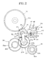
- a rotary drum 2 installed on the centre of the deck 1 is provided with a plurality of heads (not shown) for recording and/or reproducing signals on or from a tape.
- a tape loading unit 4 is placed around the outer circumference of the rotary drum 2 for transmitting the tape toward the rotary drum 2.
- the tape loading unit 4 comprises an ordinary ring gear 6, and pole bases 8 are moved along a predetermined path in accordance with the rotation of the ring gear 6 to load the tape towards the rotary drum 2.
- the deck 1 has a pair of reel tables (not shown) to which a tape cassette (not shown) is safely mounted, and these reel tables are driven in a normal way by means of an idler 10.
- the above-described tape loading unit 4 and idler 10 selectively deliver the rotational force of a capstan motor 12 disposed on the deck 1 by employing a power transmitting device 20, thereby either loading/unloading the tape on the one hand, or transporting (driving) the tape by driving the reel tables, on the other hand.
- the power transmitting device 20 has a transmission gear 21 and a rotating gear 22 both installed on a swing arm 23, in which first gear teeth 21a of the transmission gear 21 are brought into meshing engagement with gear teeth 12a of the capstan motor 12, and second gear teeth 21b thereof are in meshing engagement with first gear teeth 22a of the rotating gear 22.
- the power transmitting device 20 which functions by selectively delivering the power of the capstan motor 12 to the tape loading unit 4 and idler 10 is rotated from side to side around a shaft 25 by a positioning controller 24 provided on one side of the swing arm 23 of the power transmitting device 20.
- the positioning controller 24 serves to selectively swing the swing arm 23 of the power transmitting device 20 from left to right.
- the power of the capstan motor 12 is transmitted to the tape loading unit 4 via a first power transmitting device.
- the first power transmitting device comprises of a series of decelerating or reduction gears comprising first, second, third and fourth gears 26, 27, 28 and 29, wherein first gear teeth 26a of the first gear 26 are selectively brought into meshing engagement with second gear teeth 22b of the rotating gear 22 in the power transmitting device 20, and second gear teeth 26b of the first gear 26 are in meshing engagement with first gear teeth 27a of the second gear 27.
- Second gear teeth 27b of the second gear 27 are brought into meshing engagement with first gear teeth 28a of the third gear 28, and second gear teeth 28b of the third gear 28 are in meshing engagement with the fourth gear 29 which is in turn brought into meshing engagement with the ring gear 6 of the tape loading unit 4.
- the power of the capstan motor 12 is transmitted to the first power transmitting device by means of the power transmitting device 20, and then properly decelerated by means of the first power transmitting device to drive the tape loading unit 4, thereby permitting the loading and unloading operations of the tape.
- the power of the capstan motor 12 is also transmitted to the idler 10 via a second power transmitting device. That is, the second power transmitting device is formed such that the first gear teeth 22a of the rotating gear 22 of the power transmitting device 20 are selectively brought into meshing engagement with first gear teeth 30a of a relay gear 30, and second gear teeth 30b of the relay gear 30 are in meshing engagement with a gear 31a of a driving pulley 31.
- the driving pulley 31 is connected to a driven pulley 34 which is connected to the idler 10 by an arm 32, and gear teeth 34a of the driven pulley 34 are in meshing engagement with the idler 10. Therefore, the power of the capstan motor 12 is transmitted to the idler 10 which in turn rotates the reel tables.
- a cassette-in sensor perceives the seating of the tape cassette to rotate the capstan motor 12, and the positioning controller 24 allows the swing arm 23 of the power transmitting device 20 to swing toward the first power transmitting device.
- the power of the capstan motor 12 is decelerated through the first to fourth gears 26, 27, 28 and 29 to be transmitted to the tape loading unit 4, thereby performing the loading and unloading operations of the tape.
- the tape-loading speed can be set in an optimum state by suitably designing the deceleration ratio of the series of decelerating gears of the first power transmitting device.
- speed-control sensors provided in the capstan motor 12 control the rotating speed of the capstan motor 12 to constantly and accurately control the tape loading speed of the tape loading unit 4.
- the positioning controller 24 makes the swing arm 23 swing toward the relay gear 30 of the second power transmitting device.
- the first gear teeth 22a of the rotating gear 22 provided in the power transmitting device 20 are brought into meshing engagement with the first gear teeth 30a of the relay gear 30, thereby rotating the relay gear 30.
- the power of the capstan motor 12 is transmitted to the idler 10 via the driving pulley 31 and driven pulley 34 which are linked to each other by means of the timing belt 36, and the idler 10 can rotate the reel tables.
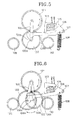
- the positioning controller 24 of Figure 1 is illustrated in Figure 2 in detail, and includes a shaking lever or armature 42 rotatably connected by a pin 41 to the end of a lever 23a projecting on one side of the swing arm 23 of the power transmitting device 20.
- the armature 42 has a permanent magnet 43 with N and S poles on a predetermined portion thereof, and one end of the lever 23a of the swing arm 23 is resiliently connected to one end of the armature 42 by means of a spring 44.
- the positioning controller 24 further includes a flanger or stator 45 installed such that the permanent magnet 43 of the armature 42 is placed to be close to first and second pole pieces 45a and 45b thereof.
- a coil 46 is wound around one side of the stator 45 to permit both ends thereof to be connected to first and second switches 47 and 48, and the polarities of portions A and B of the stator 45 are changed in accordance with the direction of current flowing through the coil 46.
- the cassette-in sensor perceives the seating of the tape cassette, to rotate the capstan motor 12.
- power is applied to the first switch 47 of the positioning controller 24 to allow the current to flow in the direction of an arrow "a" of the coil 46 shown in Figure 2, so that the portion A of the stator 45 has a polarity of S, and the portion B has a polarity of N.
- the armature 42 swings toward the first pole piece 45a by an angle ⁇ , using a line X-X as a reference.
- the second gear teeth 22b of the rotating gear 22 in the power transmitting device 20 are brought into meshing engagement with the first gear teeth 26a of the first gear 26 in the first power transmitting device to transmit the power of the capstan motor 12 to the first power transmitting device.
- the power decelerated through the first to fourth gears 26 to 29 is delivered to the tape loading unit 4 to perform the loading and unloading operations of the tape.
- the power supplied to the first switch 47 is cut off but supplied to the second switch 48 to make the current flow in the direction "b" of the coil 46.
- the portion A of the stator 45 has a polarity of N
- the portion B thereof has a polarity of S, which is contrary to the circumstance of supplying the power to the first switch 47.
- the lever 23a of the swing arm 23 at the state shown in Figure 3A swings counter-clockwise under the tension of the spring 44 to permit the first gear teeth 22a of the rotating gear 22 to be brought into meshing engagement with first gear teeth 30a of the relay gear 30 as shown in Figure 2, with the consequence of blocking the power supply by means of the first power transmitting device and shifting the power of the capstan motor 12 to the second power transmitting device.
- the power is transmitted to the idler 10 through the driving and driven pulleys 31 and 34, so that the idler 10 can rotate the reel tables.
- the lever 23a swings by as much as ⁇ ' under the tension of the spring 44.
- the lever 23a and shaking lever 42 form an angle of ⁇ - ⁇ ', which denotes a state of continuously drawing the lever 23a by the spring 44.
- the power of the capstan motor is selectively transmitted to the first or second power driving unit via the power switching units, thereby loading the tape or driving the reel tables through the first and second power transmitting devices.
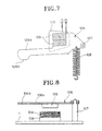
- a power transmitting device 120 includes a transmission gear 121 in meshing engagement with the gear teeth 12a of the capstan motor 12, and a rotating gear 122 in meshing engagement with the transmission gear 121 and connected thereto by a lever 100. Also, a first gear 126 and a relay gear 130 are installed on both sides of the rotating gear 122 for transmitting power toward the loading system or reel system via respective gears of the tape recorder as described above.
- a driving coil 104 is mounted on a substrate 103 of the deck 1, and an armature 106 is installed over the driving coil 104 maintaining a predetermined distance such that a permanent magnet 105 having polarities of N and S installed on the armature 106 is opposite the driving coil 104.
- the armature 106 can elastically swing resiliently against or under the bias of a spring 108 around a shaft 107 at one end thereof, and a latch plate 106b is forged on the end of an arm 106a extending at another end of the armature 106.
- the latch plate 106b catches a pin 100a formed on one end of the lever 100 for connecting the transmission gear 121 to rotating gear 122.
- the first gear 126 receives the power of the capstan motor 12 by the power transmitting device 120 to transmit it to the tape loading unit 4 via the second, third and fourth gears 27, 28 and 29, thereby performing loading and unloading operations of the tape.
- the relay gear 130 is in meshing engagement with the gear 31a of the driving pulley 31 connected to the driven pulley 34 which is connected to the idler 10 via the arm 32, using the timing belt 36.
- the gear 34a of the driven pulley 34 is brought into meshing engagement with the idler 10 to transmit the power of the capstan motor 12, thereby rotating the reel tables.
- the cassette-in sensor perceives the seating of the tape cassette, to rotate the capstan motor 12, and the transmission gear 121 in meshing engagement with the gear teeth 12a of the capstan motor 12 is rotated.
- the transmission gear 121 rotates clockwise
- the rotating gear 122 connected by means of the lever 100 swings to be brought into meshing engagement with the first gear 126 to transmit the power to the tape loading unit 4 via the second, third and fourth gears 27, 28 and 29, thereby loading and unloading the tape.
- the tape loading speed can be most properly set by suitably designing the deceleration ratio of the series of decelerating gears 126, 27, 28 and 29.
- well-known speed-control sensors provided in the capstan motor 12 control the rotating speed of the capstan motor 12 to constantly and accurately control the tape loading speed.
- the rotating gear 122 swings to right or left in accordance with the rotational direction of the transmission gear 121 to be brought into meshing engagement respectively with the first gear 126 and relay gear 130. Consequently, if the rotational direction of the transmission gear 121 is changed as required under a state of being in meshing engagement with either gear 126 or 130, the connection of the rotating gear 122 is altered.
- the inclination of the rotating gear 122 to swing can be forcibly regulated by a positioning controller as shown in FIGs 6, 7 and 8.
- a positioning controller as shown in FIGs 6, 7 and 8.
- the driving coil 104 on the substrate 103 is supplied with power to interact with the permanent magnet 105 opposite thereto, so that the armature 106 moves resiliently clockwise around the shaft 107 by means of the spring 108, as shown in Figure 5.
- the rotating gear 122 swings without being interrupted to be brought into meshing engagement with the other gear to perform its corresponding mode.
- the power supplied to the driving coil 104 is blocked to return the armature 106 to its original position by the restoring force of the spring 108.
- the rotational force of the capstan motor can be properly transmitted to the loading or reel system. Furthermore, the required power can be necessarily transmitted by means of the positioning controller to improve the function of the tape recorder.
- the power of the capstan motor is selectively transmitted to the first and second power transmitting devices via the power switching units, and the tape loading unit and reel tables are driven via the first and second power transmitting devices.
- a loading motor is dispensed with as compared with a conventional deck, which results in reducing size and weight of the deck to attain minimization. Also, cost and number of components may be decreased, to improve productivity.
Landscapes
- Gear Transmission (AREA)
- Transmission Devices (AREA)
- Structure Of Transmissions (AREA)
Claims (11)
- Dispositif de transmission de force pour un magnétophone, destiné à recevoir une force d'un moteur de cabestan (12) afin d'entraíner à la fois un système de chargement de bande (4) et un système de transport de bande, le dispositif de transmission de force comportant :des moyens de transmission de force comprenant un pignon de renvoi (21) destiné à tourner vers l'avant et vers l'arrière sous l'action du moteur de cabestan (12), et un pignon rotatif (22) destiné à pivoter suivant un angle prédéterminé autour d'un axe (25) lorsqu'il vient s'engrener avec ledit pignon de renvoi (21) ;des premiers moyens d'entraínement comprenant un premier pignon (26) monté sur une platine (1) pour transmettre une force de rotation du moteur de cabestan (12) au système de chargement en étant sélectivement engrené avec le pignon rotatif (22) ;des seconds moyens d'entraínement comprenant un pignon de relais (30) monté sur la platine (1) pour transmettre la force de rotation du moteur de cabestan (12) au système de transport de bande en étant sélectivement engrené avec le pignon rotatif (22) ; etdes moyens de contrôle de position (24) pour empêcher que le pignon rotatif (22) soit poussé et dévié de sa position lorsqu'il est entraíné par les moyens de transmission de force pour entraíner soit les premiers, soit les seconds moyens d'entraínement.
- Dispositif de transmission de force selon la revendication 1, dans lequel les moyens de transmission de force comportentle pignon de renvoi (21) pourvu de premières dents (21a) qui s'engrènent avec un pignon (12a) du moteur de cabestan (12), et de secondes dents (21b) qui s'engrènent avec les premières dents (22a) du pignon rotatif (22),le pignon rotatif (22) pourvu des premières dents (22a) qui sont engrenées sélectivement avec les secondes dents (21b) du pignon de renvoi (21) et avec le pignon de relais (30) des seconds moyens d'entraínement ; etun bras pivotant (23) qui est destiné à relier le pignon de renvoi (21) au pignon rotatif (22) et qui pivote sur l'axe (25) grâce aux moyens de contrôle de position (24).
- Dispositif de transmission de force selon la revendication 1, dans lequel les moyens de transmission de force comportent un levier (100) destiné à provoquer l'engrènement du pignon de renvoi (121) avec le pignon rotatif (122) ; et
une tige (100a) qui fait saillie à une extrémité du levier (100), du côté du pignon rotatif (122). - Dispositif de transmission de force selon les revendications 1, 2 ou 3, dans lequel les premiers moyens d'entraínement comportent une série de pignons de décélération (26-29) formée de plusieurs pignons disposés à la suite les uns des autres pour recevoir une force à partir du pignon rotatif (22) en vue d'entraíner le système de chargement de bande (4).
- Dispositif de transmission de puissance selon l'une quelconque des revendications précédentes, dans lequel les seconds moyens d'entraínement comportent le pignon de relais (30) destiné à recevoir une force à partir des moyens de transmission de force ; et une poulie d'entraínement et une poulie entraínée (31, 34) reliées par une courroie de synchronisation (36) pour transmettre une force entre le pignon de relais (30) et un galet-tendeur (10).
- Dispositif de transmission de force selon l'une quelconque des revendications, dans lequel les moyens de contrôle de position comportent une bobine de commande (104) montée sur un support (103), et une armature (106) sur laquelle un aimant permanent (105) est disposé en face de ladite bobine de commande (104) et séparé de celle-ci par une distance prédéterminée, l'armature (106) pivotant de manière élastique grâce à un ressort (108) autour d'un axe (107) pour régler la position du levier (100) du pignon rotatif (122).
- Dispositif de transmission de force selon les revendications 3 et 6, dans lequel l'armature (106) comporte une plaque de verrouillage (106b) à une extrémité d'un bras (106a) qui s'étend vers un côté de l'armature (106) pour contrôler la position de la tige saillante (100a) formée sur le levier (100).
- Dispositif de transmission de force selon les revendications 3 et 6 ou 7, dans lequel l'armature (106) pivote autour de l'axe (107) pour supprimer le blocage de la position de la tige saillante (100a) quand une force est appliquée à la bobine de commande (104), et contrôle la position de ladite tige saillante (100a) grâce à la force de rappel du ressort (108) quand une force n'est pas appliquée à la bobine de commande (104).
- Dispositif de transmission de force selon l'une quelconque des revendications 1 à 5, dans lequel les moyens de contrôle de position comportent :une armature (42) reliée en rotation, par l'intermédiaire d'une tige (41), à une extrémité d'un levier (23a) saillant sur un côté d'un bras pivotant (23) des moyens de transmission de force ;un aimant permanent (43) pour faire pivoter l'armature (42) suivant un angle prédéterminé ;un ressort (44) relié à une extrémité du levier (23a) du bras pivotant (23) et à une extrémité de l'armature (42) ; etun stator (45) présentant près de l'aimant permanent (43) de l'armature (42) une première et une seconde pièce polaire (45a, 45b).
- Dispositif de transmission de force selon la revendication 9, dans lequel le stator (45) comporte un corps et une bobine (46) enroulée sur ce corps pour fournir un courant prédéterminé, la polarité des première et seconde pièces polaires (45a, 45b) étant déterminée par le courant fourni à ladite bobine (46) pour faire pivoter le bras pivotant (23) grâce à l'interaction avec l'aimant permanent (43).
- Enregistreur et/ou lecteur à bande pourvu d'un dispositif de transmission de force ou d'une platine de bande selon l'une quelconque des revendications précédentes.
Applications Claiming Priority (6)
| Application Number | Priority Date | Filing Date | Title |
|---|---|---|---|
| KR1019920023944A KR100207609B1 (ko) | 1992-12-11 | 1992-12-11 | 테이프 레코더의 동력전달장치 |
| KR1019920023945A KR940016096A (ko) | 1992-12-11 | 1992-12-11 | 테이프 레코더의 동력절환장치 |
| KR9223944 | 1992-12-11 | ||
| KR9223945 | 1992-12-11 | ||
| KR932765 | 1993-02-26 | ||
| KR1019930002765A KR0147566B1 (ko) | 1993-02-26 | 1993-02-26 | 테이프 레코더의 동력변환장치 |
Publications (3)
| Publication Number | Publication Date |
|---|---|
| EP0606738A2 EP0606738A2 (fr) | 1994-07-20 |
| EP0606738A3 EP0606738A3 (fr) | 1994-11-17 |
| EP0606738B1 true EP0606738B1 (fr) | 1998-07-08 |
Family
ID=27348886
Family Applications (1)
| Application Number | Title | Priority Date | Filing Date |
|---|---|---|---|
| EP93310010A Expired - Lifetime EP0606738B1 (fr) | 1992-12-11 | 1993-12-13 | Dispositif de transmission de force pour enregistreur à bande |
Country Status (8)
| Country | Link |
|---|---|
| US (1) | US5600507A (fr) |
| EP (1) | EP0606738B1 (fr) |
| JP (1) | JP2731714B2 (fr) |
| CN (1) | CN1042176C (fr) |
| CA (1) | CA2111184C (fr) |
| DE (1) | DE69319570T2 (fr) |
| ES (1) | ES2121061T3 (fr) |
| RU (1) | RU2125301C1 (fr) |
Families Citing this family (1)
| Publication number | Priority date | Publication date | Assignee | Title |
|---|---|---|---|---|
| RU2686994C1 (ru) * | 2018-09-11 | 2019-05-06 | Алексей Владимирович Ражев | Гомокинетический шарнир |
Family Cites Families (14)
| Publication number | Priority date | Publication date | Assignee | Title |
|---|---|---|---|---|
| US4221316A (en) * | 1977-03-31 | 1980-09-09 | International Tapetronics Corporation | NAB Tape cartridge eraser and splice finder |
| JPS5718047A (en) * | 1980-07-09 | 1982-01-29 | Hitachi Ltd | Magnetic recording and reproducing device |
| EP0045328B1 (fr) * | 1980-08-06 | 1983-11-23 | Efuti Giken Co.,LTD. | Mécanisme de chargement pour un enregistreur de cassette à bande |
| JPS57135472A (en) * | 1981-02-16 | 1982-08-21 | Toshiba Corp | Video tape recorder |
| US4594624A (en) * | 1981-12-09 | 1986-06-10 | Matsushita Electric Industrial Co., Ltd. | Magnetic tape recording and/or reproducing apparatus with variable capstan torque transmission means |
| JPS58153255A (ja) * | 1982-03-05 | 1983-09-12 | Matsushita Electric Ind Co Ltd | 磁気テ−プ装置 |
| JPS59149251U (ja) * | 1983-03-22 | 1984-10-05 | 日本ビクター株式会社 | テ−プ自動装填型記録再生装置 |
| JPS6117251A (ja) * | 1984-07-04 | 1986-01-25 | Toshiba Corp | 磁気記録再生装置 |
| JPS61188771A (ja) * | 1985-02-18 | 1986-08-22 | Matsushita Electric Ind Co Ltd | 磁気記録再生装置 |
| JPH0834022B2 (ja) * | 1987-05-29 | 1996-03-29 | 松下電器産業株式会社 | 磁気テ−プ装置 |
| KR900007830Y1 (ko) * | 1987-09-15 | 1990-08-24 | 주식회사 금성사 | 브이씨알의 캡스턴 모터를 이용한 카세트로딩장치 |
| JPH04283453A (ja) * | 1991-03-11 | 1992-10-08 | Canon Inc | テープ搬送装置及びその制御方法 |
| KR100195072B1 (ko) * | 1993-02-26 | 1999-06-15 | 윤종용 | 정보 기록 및 재생 시스템 |
| KR0141235B1 (ko) * | 1993-07-30 | 1998-07-15 | 김광호 | 테이프 레코더의 동력변환장치 |
-
1993
- 1993-12-08 JP JP5308023A patent/JP2731714B2/ja not_active Expired - Fee Related
- 1993-12-08 RU RU93054515A patent/RU2125301C1/ru not_active IP Right Cessation
- 1993-12-10 CA CA002111184A patent/CA2111184C/fr not_active Expired - Fee Related
- 1993-12-11 CN CN93121149A patent/CN1042176C/zh not_active Expired - Fee Related
- 1993-12-13 DE DE69319570T patent/DE69319570T2/de not_active Expired - Fee Related
- 1993-12-13 ES ES93310010T patent/ES2121061T3/es not_active Expired - Lifetime
- 1993-12-13 EP EP93310010A patent/EP0606738B1/fr not_active Expired - Lifetime
-
1995
- 1995-09-12 US US08/526,864 patent/US5600507A/en not_active Expired - Lifetime
Also Published As
| Publication number | Publication date |
|---|---|
| ES2121061T3 (es) | 1998-11-16 |
| CA2111184A1 (fr) | 1994-06-12 |
| JPH06295493A (ja) | 1994-10-21 |
| EP0606738A2 (fr) | 1994-07-20 |
| CN1042176C (zh) | 1999-02-17 |
| CN1090942A (zh) | 1994-08-17 |
| DE69319570D1 (de) | 1998-08-13 |
| CA2111184C (fr) | 2002-02-05 |
| DE69319570T2 (de) | 1998-11-05 |
| EP0606738A3 (fr) | 1994-11-17 |
| JP2731714B2 (ja) | 1998-03-25 |
| US5600507A (en) | 1997-02-04 |
| RU2125301C1 (ru) | 1999-01-20 |
Similar Documents
| Publication | Publication Date | Title |
|---|---|---|
| KR880002575Y1 (ko) | 비디오 테이프 레코오더의 릴 구동장치 | |
| US4760751A (en) | Rotary driving mechanism | |
| US5180117A (en) | Video tape recorder and/or reproducer | |
| US4903149A (en) | Tape cassette loading system for a magnetic recording and reproducing apparatus | |
| EP0606738B1 (fr) | Dispositif de transmission de force pour enregistreur à bande | |
| US6466395B1 (en) | Magnetic recording and reproducing apparatus | |
| EP0395299B1 (fr) | Système d'entraînement dans un appareil d'enregistrement et/ou de reproduction | |
| KR930022307A (ko) | 자기기록 재생장치 및 그 모드 제어방법 | |
| US5508858A (en) | Power transferring device for magnetic recording and reproducing apparatus using an electromagnetic plunger | |
| KR840002563A (ko) | 자기식(磁氣式) 녹화, 재생장치의 리일(reel) 구동장치 | |
| KR100207609B1 (ko) | 테이프 레코더의 동력전달장치 | |
| KR0147566B1 (ko) | 테이프 레코더의 동력변환장치 | |
| EP0613132B1 (fr) | Guidage de bande dans un appareil d'enregistrement à bande | |
| JPH045080Y2 (fr) | ||
| US5901914A (en) | Recording and/or reproducing apparatus permitting selective use of cassettes of different sizes | |
| KR100189930B1 (ko) | 테이프 릴 구동장치 | |
| JP3082609B2 (ja) | テープレコーダ | |
| US5467234A (en) | Idler controlling apparatus of a magnetic recording/reproducing apparatus | |
| JPH0423654A (ja) | 留守番電話自動応答装置 | |
| KR940001596B1 (ko) | 테이프 레코더의 아이들러 제어장치 | |
| KR100188656B1 (ko) | 테이프 레코더의 릴테이블 구동 변환장치 | |
| KR0155802B1 (ko) | 테이프 레코더의 기어 변환장치 | |
| KR0121156B1 (ko) | 헤드폰 스테레오 카세트 테이프 레코더의 모드 변환장치 | |
| JPS5911560A (ja) | 磁気記録再生装置 | |
| JPH02260259A (ja) | テープレコーダ装置 |
Legal Events
| Date | Code | Title | Description |
|---|---|---|---|
| PUAI | Public reference made under article 153(3) epc to a published international application that has entered the european phase |
Free format text: ORIGINAL CODE: 0009012 |
|
| AK | Designated contracting states |
Kind code of ref document: A2 Designated state(s): DE ES FR GB |
|
| PUAL | Search report despatched |
Free format text: ORIGINAL CODE: 0009013 |
|
| AK | Designated contracting states |
Kind code of ref document: A3 Designated state(s): DE ES FR GB |
|
| 17P | Request for examination filed |
Effective date: 19950420 |
|
| 17Q | First examination report despatched |
Effective date: 19970203 |
|
| GRAG | Despatch of communication of intention to grant |
Free format text: ORIGINAL CODE: EPIDOS AGRA |
|
| GRAG | Despatch of communication of intention to grant |
Free format text: ORIGINAL CODE: EPIDOS AGRA |
|
| GRAH | Despatch of communication of intention to grant a patent |
Free format text: ORIGINAL CODE: EPIDOS IGRA |
|
| GRAH | Despatch of communication of intention to grant a patent |
Free format text: ORIGINAL CODE: EPIDOS IGRA |
|
| GRAA | (expected) grant |
Free format text: ORIGINAL CODE: 0009210 |
|
| AK | Designated contracting states |
Kind code of ref document: B1 Designated state(s): DE ES FR GB |
|
| REF | Corresponds to: |
Ref document number: 69319570 Country of ref document: DE Date of ref document: 19980813 |
|
| REG | Reference to a national code |
Ref country code: ES Ref legal event code: FG2A Ref document number: 2121061 Country of ref document: ES Kind code of ref document: T3 |
|
| ET | Fr: translation filed | ||
| PLBE | No opposition filed within time limit |
Free format text: ORIGINAL CODE: 0009261 |
|
| STAA | Information on the status of an ep patent application or granted ep patent |
Free format text: STATUS: NO OPPOSITION FILED WITHIN TIME LIMIT |
|
| 26N | No opposition filed | ||
| REG | Reference to a national code |
Ref country code: GB Ref legal event code: IF02 |
|
| PGFP | Annual fee paid to national office [announced via postgrant information from national office to epo] |
Ref country code: GB Payment date: 20071212 Year of fee payment: 15 Ref country code: FR Payment date: 20071210 Year of fee payment: 15 Ref country code: ES Payment date: 20080118 Year of fee payment: 15 |
|
| PGFP | Annual fee paid to national office [announced via postgrant information from national office to epo] |
Ref country code: DE Payment date: 20071206 Year of fee payment: 15 |
|
| GBPC | Gb: european patent ceased through non-payment of renewal fee |
Effective date: 20081213 |
|
| REG | Reference to a national code |
Ref country code: FR Ref legal event code: ST Effective date: 20090831 |
|
| PG25 | Lapsed in a contracting state [announced via postgrant information from national office to epo] |
Ref country code: DE Free format text: LAPSE BECAUSE OF NON-PAYMENT OF DUE FEES Effective date: 20090701 |
|
| PG25 | Lapsed in a contracting state [announced via postgrant information from national office to epo] |
Ref country code: GB Free format text: LAPSE BECAUSE OF NON-PAYMENT OF DUE FEES Effective date: 20081213 |
|
| REG | Reference to a national code |
Ref country code: ES Ref legal event code: FD2A Effective date: 20081215 |
|
| PG25 | Lapsed in a contracting state [announced via postgrant information from national office to epo] |
Ref country code: FR Free format text: LAPSE BECAUSE OF NON-PAYMENT OF DUE FEES Effective date: 20081231 Ref country code: ES Free format text: LAPSE BECAUSE OF NON-PAYMENT OF DUE FEES Effective date: 20081215 |