EP0607023A2 - Appareil d'impression pour ruban - Google Patents
Appareil d'impression pour ruban Download PDFInfo
- Publication number
- EP0607023A2 EP0607023A2 EP94300191A EP94300191A EP0607023A2 EP 0607023 A2 EP0607023 A2 EP 0607023A2 EP 94300191 A EP94300191 A EP 94300191A EP 94300191 A EP94300191 A EP 94300191A EP 0607023 A2 EP0607023 A2 EP 0607023A2
- Authority
- EP
- European Patent Office
- Prior art keywords
- cassette
- printing apparatus
- switching
- cover member
- receiving bay
- Prior art date
- Legal status (The legal status is an assumption and is not a legal conclusion. Google has not performed a legal analysis and makes no representation as to the accuracy of the status listed.)
- Granted
Links
Images


Classifications
-
- B—PERFORMING OPERATIONS; TRANSPORTING
- B41—PRINTING; LINING MACHINES; TYPEWRITERS; STAMPS
- B41J—TYPEWRITERS; SELECTIVE PRINTING MECHANISMS, i.e. MECHANISMS PRINTING OTHERWISE THAN FROM A FORME; CORRECTION OF TYPOGRAPHICAL ERRORS
- B41J29/00—Details of, or accessories for, typewriters or selective printing mechanisms not otherwise provided for
- B41J29/38—Drives, motors, controls or automatic cut-off devices for the entire printing mechanism
- B41J29/387—Automatic cut-off devices
-
- B—PERFORMING OPERATIONS; TRANSPORTING
- B41—PRINTING; LINING MACHINES; TYPEWRITERS; STAMPS
- B41J—TYPEWRITERS; SELECTIVE PRINTING MECHANISMS, i.e. MECHANISMS PRINTING OTHERWISE THAN FROM A FORME; CORRECTION OF TYPOGRAPHICAL ERRORS
- B41J3/00—Typewriters or selective printing or marking mechanisms characterised by the purpose for which they are constructed
- B41J3/407—Typewriters or selective printing or marking mechanisms characterised by the purpose for which they are constructed for marking on special material
- B41J3/4075—Tape printers; Label printers
-
- B—PERFORMING OPERATIONS; TRANSPORTING
- B41—PRINTING; LINING MACHINES; TYPEWRITERS; STAMPS
- B41J—TYPEWRITERS; SELECTIVE PRINTING MECHANISMS, i.e. MECHANISMS PRINTING OTHERWISE THAN FROM A FORME; CORRECTION OF TYPOGRAPHICAL ERRORS
- B41J35/00—Other apparatus or arrangements associated with, or incorporated in, ink-ribbon mechanisms
- B41J35/28—Detachable carriers or holders for ink-ribbon mechanisms
Definitions
- the invention relates generally to tape printing apparatus and in particular to apparatus which is capable of receiving a cassette containing a printing tape.
- Printing apparatus of the type with which the present invention is concerned include thermal printers of the type disclosed in EP-A-322918 and EP-A-322919 (Brother Kogyo Kabushiki Kaisha) and EP-A-0267890 (Varitronics). These printers each include a printing device having a cassette receiving bay for receiving a cassette or tape holding case.
- the tape holding case houses an ink ribbon and a substrate tape, the latter comprising an upper image receiving layer secured to a backing layer by adhesive.
- the tape holding case houses an ink ribbon, a transparent image receiving tape and a double-sided adhesive tape which is secured at one of its adhesive-coated sides to the image tape after printing and which has a backing layer peelable from its other adhesive-coated side.
- the image transfer medium (ink ribbon) and image receiving tape (substrate) are in the same cassette.
- the substrate tape is similar to that described in EP-A-0267890 but is housed in its own tape holding case while the ink ribbon is similarly housed in its own tape holding case.
- the image receiving tape passes in overlap with the ink ribbon through a print zone consisting of a print head and a platen against which the print head can be pressed to cause an image to transfer from the ink ribbon to the image receiving tape.
- a print zone consisting of a print head and a platen against which the print head can be pressed to cause an image to transfer from the ink ribbon to the image receiving tape.
- thermal printing where the print head is heated and the heat causes ink from the ink ribbon to be transferred to the image receiving tape.
- the tape holding case with the ink ribbon is placed on one side of the print zone while the tape holding case with the substrate is placed on the other side of the print zone.
- the tape holding case is commonly referred to as a cassette.
- the printing apparatus of GB 9212423.9 and of EP 322919 have a lid or cover member which covers a cassette receiving bay arranged to receive the cassette. It is one object of the present invention to inhibit operation of the printer unless the lid or cover member is in its correct position.
- a printing apparatus having a cassette receiving bay for receiving a cassette having printing tape; a cover member movable between an open position in which a cassette can be inserted into the cassette receiving bay and a closed position in which the cover member covers the cassette receiving bay; and a switching mechanism operable in response to movement of the cover member to permit operation of the printing apparatus only when the cover member is in the closed position.
- the cassette receiving bay can be adjacent the keyboard with the cover member comprising a lid hinged to a main body of the printer to open upwardly.
- the switching mechanism is also operable in response to the presence or absence of a cassette in the cassette receiving bay so that operation of the printing apparatus is permitted only in the presence of a cassette and with the lid in the closed position.
- the present invention relates in the preferred embodiment particularly to detection of the presence or absence of the ink ribbon cassette.
- the invention is not restricted to detection of the ink ribbon cassette but could be used for the detection of cassettes housing substrate tape or a plurality of tapes.
- the invention also provides in combination: a printing apparatus having a cassette receiving bay for receiving a cassette housing printing tape, a cover member movable between an open position in which a cassette can be inserted into the cassette receiving bay and a closed position in which the cover member covers the cassette receiving bay, and a switching mechanism; and a cassette inserted in, or for insertion in, the cassette receiving bay and having means operable to actuate said switching mechanism to permit operation of the printing apparatus only when a cassette is inserted and with the cover member in the closed position, printing operations otherwise being inhibited.
- the invention can be used in any type of printing apparatus where a cassette is needed for use in printing. As described herein the invention is applied to the presence or absence of a cassette containing ink ribbon but the principle is applicable to other types of cassettes. The invention is particularly applicable where two cassettes are required and where detection means is provided for both cassettes. Suitable detection means for the image receiving tape casette are described in our copending Application No. 9212004.7 the contents of which are herein incorporated by reference. If the detection means for the substrate cassette should fail, it is particularly advantageous to ensure that the printing apparatus cannot operate unless the ink ribbon cassette at least is present.
- the printing apparatus will generally comprise printing means in the form of a print head and platen at a print zone.
- the movement of the lid automatically causes the print head to come into contact with the platen so that the "lid closed” position is synonymous with a "print ready” state at the print zone.
- the "lid closed" position is synonymous with a "print ready” state at the print zone.
- the invention has the advantage that printing is inhibited in both the conditions that the lid is open and that there is no cassette present. Thus an incautious user cannot operate the printing apparatus in a way which could cause damage to it.
- the switching mechanism comprises a switch with first and second switching terminals and first and second switch actuating means associated respectively with the first and second switching terminals, the first switch actuating means being associated with the cover member and the second switch actuating means being associated with the cassette.
- the first switch actuating means can comprise a switching member movable with the cover member to cause it to bring the first terminal into contact with the second terminal when the cover member is open.
- the second switch actuating means can comprise a switching member biased in a direction such that the first and second terminals are in contact, regardless of the position of the first switch actuating means, the switching member being movable in response to the actuating means in the cassette to cause the second terminal to come out of contact with the first terminal.
- the arrangement is such that the second switching member is then only brought out of contact with the first switching member when the cassette is inserted and the cover member is closed.
- the switching member of the second switch actuating means can comprise a switching block pivotably mounted with respect to a base of the cassette receiving bay and having a part protruding above the base, the cassette having a slot which engages the protruding part and thus causes the switching block to pivot against its biased direction.
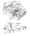
- Figure 1 shows in plan view part of the main body 1 of a printing device with two cassettes arranged in a cassette receiving bay 13.
- the upper cassette 2 contains a supply of image receiving tape 4 which passes through a print zone 3 of the printer to an outlet 5 of the printer.
- the image receiving tape 4 comprises an upper layer for receiving a printed image on one of its surfaces and having its other surface coated with an adhesive layer to which is secured a releaseable backing layer.
- the upper cassette 2 has a recess 6 for accommodating a platen 8 of the printer.
- the platen is mounted for rotation on a pin.
- the platen could be mounted for rotation within a cage moulding.
- the lower cassette 7 contains an ink ribbon 12 which extends from a supply spool to a take-up spool within the lower cassette 7.
- the ink ribbon 12 extends through the print zone in overlap with the image receiving tape 4.
- the lower cassette 7 has a recess 17 for receiving a print head 16 of the printer.
- the print head is movable between an operative position in which it is in contact with the platen 8 and holds the thermal transfer ribbon 12 and the image receiving tape 4 in overlap between the print head 16 and the platen 8 and an inoperative position (shown in Figure 1) in which it is held away from the platen 8 to release the thermal transfer ribbon 12 and image receiving tape 4.
- the main body 1 carries a keyboard (not shown), display (shown partially at D) and other usual features of the printing apparatus.
- the cassette receiving bay 13 has a lid 15 which is hingedly mounted to the main body and which can be pivoted between an open position (shown in Figure 1) and a closed position.
- the print head 16 is connected to the lid through a mechanical linkage (24 in Figure 2) so that when the lid is opened the print head is automatically brought into its inoperative position and when the lid is closed it is brought into its operative position. This can be accomplished as described in Application EP-A-0487313.
- FIG. 2 shows a switching mechanism for detecting whether or not the lid is closed and whether or not the lower cassette 7 is in place.
- the switching mechanism comprises a microswitch 20 which is mounted under the floor of the cassette receiving bay for the lower cassette.
- the microswitch 20 has upper and lower terminals 20a,20b mounted on respective leaf springs and which when in contact prohibit operation of the printing apparatus.
- the print head 16 (not shown in Figure 2) is supported on a print head arm 22 which moves with the mechanical linkage 24 coupled to the lid.
- the print head arm 22 carries a print head arm switching member 26 which, with the lid open and the print head in the inoperative position, bears on a contact 28 which depresses the upper terminal 20a into contact with the lower terminal 20b.
- the switching mechanism also comprises a switching block 32 which is pivotably mounted on a pin 34 and which is also located under the floor of the cassette receiving bay.
- the switching block 32 is biased upwardly in the Figures (rearwardly in an actual printing apparatus) by means of a spring 36 acting against a pin 38.
- the switching block 32 carries a switching piece 33 which defines, still under the floor of the cassette receiving bay, an abutment surface 30 which lies under the leaf springs and which serves to prevent the print head arm switching member 26 from pushing the terminal 20a too far downwards.
- the switching piece 33 also has, extending through the floor of the cassette receiving bay, an angled block 40. As can be seen most clearly in Figure 6, the angled block has a sloping surface 44 which slopes downwardly (forwardly in an actual printing apparatus).
- the switching block 32 also has a switching surface 35 located under the floor of the cassette receiving bay, to cooperate with the lower switching terminal 20b.
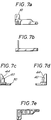
- Figures 7a to 7e show different elevations of the switching block to show its construction more clearly.
- the abutment surface 30 which serves to prevent the switching member from pushing the terminal 20a too far downwards
- the switching surface 35 which serves to cooperate with the lower switching terminal 20b and the angle block 40 which serves to be received by a slot 50 of the lower cassette 7.
- the action of the print head arm switching member 26 on the contact 28 causes the terminal 20a to be in contact with the terminal 20b.
- the action of the switching member 26 on the abutment surface 30 pushes the switching block downwardly in the Figure against the action of the spring 36.
- the switching block 32 is biased rearwardly in the printing apparatus (that is, towards the rear of the cassette receiving bay) to bring the switching surface 35 into contact with the leaf spring carrying the contact terminal 20b so that this is pushed up into contact with the terminal 20a.
- the abutment surface 30 eventually abuts the switching member 26 and so prevents the switching block from forcing the leaf springs too far in the rearward direction.
- the lower cassette 7 for use with this switching mechanism has a slot 50 sized to receive the angled block 40.
- the rearward edge 50a of the slot slides over the sloping surface 44 and causes the angled block and thus the switching block 32 to be pulled forward against the action of the spring 36.
- the switching surface 35 no longer contacts the leaf spring carrying the lower terminal 20b.
Landscapes
- Accessory Devices And Overall Control Thereof (AREA)
- Printers Characterized By Their Purpose (AREA)
- Impression-Transfer Materials And Handling Thereof (AREA)
- Handling Of Continuous Sheets Of Paper (AREA)
Applications Claiming Priority (2)
| Application Number | Priority Date | Filing Date | Title |
|---|---|---|---|
| GB939300586A GB9300586D0 (en) | 1993-01-13 | 1993-01-13 | Tape printing apparatus |
| GB9300586 | 1993-01-13 |
Publications (3)
| Publication Number | Publication Date |
|---|---|
| EP0607023A2 true EP0607023A2 (fr) | 1994-07-20 |
| EP0607023A3 EP0607023A3 (fr) | 1994-12-07 |
| EP0607023B1 EP0607023B1 (fr) | 1998-12-02 |
Family
ID=10728657
Family Applications (1)
| Application Number | Title | Priority Date | Filing Date |
|---|---|---|---|
| EP94300191A Expired - Lifetime EP0607023B1 (fr) | 1993-01-13 | 1994-01-12 | Appareil d'impression pour ruban |
Country Status (6)
| Country | Link |
|---|---|
| US (1) | US5437511A (fr) |
| EP (1) | EP0607023B1 (fr) |
| JP (1) | JPH06316127A (fr) |
| AU (1) | AU673024B2 (fr) |
| DE (2) | DE69414883T2 (fr) |
| GB (1) | GB9300586D0 (fr) |
Cited By (5)
| Publication number | Priority date | Publication date | Assignee | Title |
|---|---|---|---|---|
| EP0743189A4 (fr) * | 1994-12-02 | 1997-03-12 | Seiko Epson Corp | Mechanisme de liberation d'une tete d'imprimante |
| EP0734871A3 (fr) * | 1995-03-29 | 1997-05-07 | Brother Ind Ltd | Dispositif d'impression d'étiquettes en forme de bande |
| EP0787591A1 (fr) * | 1996-01-31 | 1997-08-06 | Brother Kogyo Kabushiki Kaisha | Dispositif d'impression d'étiquettes en forme de bande |
| EP0794066A1 (fr) * | 1996-03-07 | 1997-09-10 | Esselte N.V. | Mécanisme indiquant la présence d'un ruban dans un appareil d'impression de bande |
| US6132120A (en) * | 1995-03-29 | 2000-10-17 | Brother Kogyo Kabushiki Kaisha | Tape-shaped label printing device |
Families Citing this family (6)
| Publication number | Priority date | Publication date | Assignee | Title |
|---|---|---|---|---|
| US5601373A (en) * | 1996-01-29 | 1997-02-11 | Intermec Corporation | Spur gear ratchet mechanism for thermal transfer printer |
| US5807005A (en) * | 1997-05-12 | 1998-09-15 | Lexmark International, Inc. | Cartridge lockout system and method |
| MX2007006388A (es) | 2004-11-30 | 2007-06-20 | Panduit Corp | Sistema y metodo de etiquetado basado en el mercado. |
| GB2459531B (en) | 2008-04-29 | 2010-10-13 | Dymo Nv | Label printer |
| JP6277028B2 (ja) * | 2014-03-24 | 2018-02-07 | セイコーエプソン株式会社 | テープカートリッジ |
| US11123999B2 (en) | 2018-09-03 | 2021-09-21 | Sanford, L.P. | Cassettes and label printers therefor |
Family Cites Families (15)
| Publication number | Priority date | Publication date | Assignee | Title |
|---|---|---|---|---|
| JPS5851173A (ja) * | 1981-09-22 | 1983-03-25 | Nec Corp | シリアルプリンタの活字選択制御方式 |
| ATE40078T1 (de) * | 1984-11-14 | 1989-02-15 | Mannesmann Tally Gmbh | Drucker, insbesondere matrixdrucker. |
| DE3545912C2 (de) * | 1984-12-28 | 1995-07-13 | Canon Kk | Drucker |
| JPS61181671A (ja) * | 1985-02-08 | 1986-08-14 | Ricoh Co Ltd | プリンタ |
| JPS61189971A (ja) * | 1985-02-18 | 1986-08-23 | Ricoh Co Ltd | プリンタ |
| JPS61229585A (ja) * | 1985-04-05 | 1986-10-13 | Hitachi Ltd | 感熱転写記録装置 |
| US4798485A (en) * | 1986-03-25 | 1989-01-17 | Brother Kogyo Kabushiki Kaisha | Electronic typewriter with a detector switch |
| JPS62238779A (ja) * | 1986-04-10 | 1987-10-19 | Matsushita Electric Ind Co Ltd | プリンタ |
| US5028934A (en) * | 1988-10-31 | 1991-07-02 | Seiko Epson Corporation | Hand-held portable printing system |
| JPH0719805Y2 (ja) * | 1989-02-08 | 1995-05-10 | ブラザー工業株式会社 | 印字装置 |
| US4943815A (en) * | 1989-06-29 | 1990-07-24 | International Business Machines Corporation | Laser printer with light-exposure prevention |
| JP2841573B2 (ja) * | 1989-11-09 | 1998-12-24 | セイコーエプソン株式会社 | テープ印刷装置 |
| US5193919A (en) * | 1989-11-09 | 1993-03-16 | Seiko Epson Corporation | Tape printer |
| DE69108443T2 (de) * | 1990-05-17 | 1995-09-21 | Seiko Epson Corp | Streifendrucker. |
| GB2250716A (en) * | 1990-11-20 | 1992-06-17 | Esselte Dymo Nv | Lid-responsive release of thermal printhead in printer using cassetted ink-ribbon. |
-
1993
- 1993-01-13 GB GB939300586A patent/GB9300586D0/en active Pending
-
1994
- 1994-01-11 US US08/180,210 patent/US5437511A/en not_active Expired - Lifetime
- 1994-01-12 DE DE69414883T patent/DE69414883T2/de not_active Expired - Lifetime
- 1994-01-12 EP EP94300191A patent/EP0607023B1/fr not_active Expired - Lifetime
- 1994-01-12 AU AU53158/94A patent/AU673024B2/en not_active Expired
- 1994-01-12 DE DE0607023T patent/DE607023T1/de active Pending
- 1994-01-13 JP JP6002036A patent/JPH06316127A/ja active Pending
Cited By (8)
| Publication number | Priority date | Publication date | Assignee | Title |
|---|---|---|---|---|
| EP0743189A4 (fr) * | 1994-12-02 | 1997-03-12 | Seiko Epson Corp | Mechanisme de liberation d'une tete d'imprimante |
| US6113292A (en) * | 1994-12-02 | 2000-09-05 | Seiko Epson Corporation | Printer head release mechanism |
| EP0734871A3 (fr) * | 1995-03-29 | 1997-05-07 | Brother Ind Ltd | Dispositif d'impression d'étiquettes en forme de bande |
| US6132120A (en) * | 1995-03-29 | 2000-10-17 | Brother Kogyo Kabushiki Kaisha | Tape-shaped label printing device |
| EP0787591A1 (fr) * | 1996-01-31 | 1997-08-06 | Brother Kogyo Kabushiki Kaisha | Dispositif d'impression d'étiquettes en forme de bande |
| EP0794066A1 (fr) * | 1996-03-07 | 1997-09-10 | Esselte N.V. | Mécanisme indiquant la présence d'un ruban dans un appareil d'impression de bande |
| WO1997032731A1 (fr) * | 1996-03-07 | 1997-09-12 | Esselte N.V. | Appareil a imprimer des bandes |
| US6017159A (en) * | 1996-03-07 | 2000-01-25 | Esselte Nv | Tape printing apparatus |
Also Published As
| Publication number | Publication date |
|---|---|
| DE69414883D1 (de) | 1999-01-14 |
| DE69414883T2 (de) | 1999-05-12 |
| JPH06316127A (ja) | 1994-11-15 |
| EP0607023B1 (fr) | 1998-12-02 |
| EP0607023A3 (fr) | 1994-12-07 |
| AU673024B2 (en) | 1996-10-24 |
| US5437511A (en) | 1995-08-01 |
| GB9300586D0 (en) | 1993-03-03 |
| DE607023T1 (de) | 1995-04-06 |
| AU5315894A (en) | 1994-07-21 |
Similar Documents
| Publication | Publication Date | Title |
|---|---|---|
| US5540510A (en) | Printing device for receiving at least two different types of tape holding cases | |
| EP0512168B1 (fr) | Appareil d'impression pour ruban | |
| EP1084852B1 (fr) | Cassette et méchanisme pour détecter si elle est installée | |
| US5165806A (en) | Thermal printer with movable drive roll | |
| US6249302B1 (en) | Thermal printing | |
| US5437511A (en) | Tape printing apparatus | |
| EP0734879B1 (fr) | Imprimante et cassette composée incluant une cassette à bande et une cassette à ruban utilisée dans l'imprimante | |
| JP3335433B2 (ja) | テープカセット | |
| US6435744B1 (en) | Tape printing device and tape cassette | |
| EP2390099B1 (fr) | Imprimante | |
| EP0743189A1 (fr) | Mechanisme de liberation d'une tete d'imprimante | |
| JPWO1996016815A1 (ja) | 印字装置のヘッドリリース機構 | |
| US5857788A (en) | Thermal printing device with direct thermal cassette | |
| EP0577271A2 (fr) | Dispositif pour l'impression sur bandes | |
| JPH07164680A (ja) | テーププリンターおよび印字テープカセット | |
| JP2001150777A (ja) | 印字装置におけるカセット収納検出装置及びカセット | |
| US6092946A (en) | Tape printing apparatus and tape holding case with a sliding switch | |
| CA1052721A (fr) | Mecanismes de fonctions automatiques simples et a repetition pour machines a ecrire | |
| JP2969156B2 (ja) | 印字装置 | |
| JP3419010B2 (ja) | プリンタ | |
| JPS61121985A (ja) | テ−プ材部分検出装置 | |
| JP7785901B2 (ja) | サーマルヘッド | |
| EP0748696A2 (fr) | Imprimante pour ruban | |
| JP2563063Y2 (ja) | 切断装置 | |
| JP2017080982A (ja) | プリンタ |
Legal Events
| Date | Code | Title | Description |
|---|---|---|---|
| PUAI | Public reference made under article 153(3) epc to a published international application that has entered the european phase |
Free format text: ORIGINAL CODE: 0009012 |
|
| AK | Designated contracting states |
Kind code of ref document: A2 Designated state(s): DE FR GB IT |
|
| ITCL | It: translation for ep claims filed |
Representative=s name: BARZANO' E ZANARDO MILANO S.P.A. |
|
| PUAL | Search report despatched |
Free format text: ORIGINAL CODE: 0009013 |
|
| EL | Fr: translation of claims filed | ||
| AK | Designated contracting states |
Kind code of ref document: A3 Designated state(s): DE FR GB IT |
|
| 17P | Request for examination filed |
Effective date: 19950201 |
|
| DET | De: translation of patent claims | ||
| RAP1 | Party data changed (applicant data changed or rights of an application transferred) |
Owner name: ESSELTE N.V. |
|
| 17Q | First examination report despatched |
Effective date: 19970115 |
|
| GRAG | Despatch of communication of intention to grant |
Free format text: ORIGINAL CODE: EPIDOS AGRA |
|
| GRAG | Despatch of communication of intention to grant |
Free format text: ORIGINAL CODE: EPIDOS AGRA |
|
| GRAH | Despatch of communication of intention to grant a patent |
Free format text: ORIGINAL CODE: EPIDOS IGRA |
|
| GRAH | Despatch of communication of intention to grant a patent |
Free format text: ORIGINAL CODE: EPIDOS IGRA |
|
| GRAA | (expected) grant |
Free format text: ORIGINAL CODE: 0009210 |
|
| AK | Designated contracting states |
Kind code of ref document: B1 Designated state(s): DE FR GB IT |
|
| PG25 | Lapsed in a contracting state [announced via postgrant information from national office to epo] |
Ref country code: IT Free format text: LAPSE BECAUSE OF FAILURE TO SUBMIT A TRANSLATION OF THE DESCRIPTION OR TO PAY THE FEE WITHIN THE PRESCRIBED TIME-LIMIT;WARNING: LAPSES OF ITALIAN PATENTS WITH EFFECTIVE DATE BEFORE 2007 MAY HAVE OCCURRED AT ANY TIME BEFORE 2007. THE CORRECT EFFECTIVE DATE MAY BE DIFFERENT FROM THE ONE RECORDED. Effective date: 19981202 |
|
| REF | Corresponds to: |
Ref document number: 69414883 Country of ref document: DE Date of ref document: 19990114 |
|
| ET | Fr: translation filed | ||
| PLBE | No opposition filed within time limit |
Free format text: ORIGINAL CODE: 0009261 |
|
| STAA | Information on the status of an ep patent application or granted ep patent |
Free format text: STATUS: NO OPPOSITION FILED WITHIN TIME LIMIT |
|
| 26N | No opposition filed | ||
| REG | Reference to a national code |
Ref country code: GB Ref legal event code: IF02 |
|
| REG | Reference to a national code |
Ref country code: FR Ref legal event code: CD |
|
| PGFP | Annual fee paid to national office [announced via postgrant information from national office to epo] |
Ref country code: FR Payment date: 20130211 Year of fee payment: 20 Ref country code: DE Payment date: 20130129 Year of fee payment: 20 Ref country code: GB Payment date: 20130125 Year of fee payment: 20 |
|
| REG | Reference to a national code |
Ref country code: DE Ref legal event code: R071 Ref document number: 69414883 Country of ref document: DE |
|
| REG | Reference to a national code |
Ref country code: GB Ref legal event code: PE20 Expiry date: 20140111 |
|
| PG25 | Lapsed in a contracting state [announced via postgrant information from national office to epo] |
Ref country code: DE Free format text: LAPSE BECAUSE OF EXPIRATION OF PROTECTION Effective date: 20140114 Ref country code: GB Free format text: LAPSE BECAUSE OF EXPIRATION OF PROTECTION Effective date: 20140111 |