EP0607084A1 - Système de modification des specifications de produit dans une machine d'ondulation - Google Patents
Système de modification des specifications de produit dans une machine d'ondulation Download PDFInfo
- Publication number
- EP0607084A1 EP0607084A1 EP94400070A EP94400070A EP0607084A1 EP 0607084 A1 EP0607084 A1 EP 0607084A1 EP 94400070 A EP94400070 A EP 94400070A EP 94400070 A EP94400070 A EP 94400070A EP 0607084 A1 EP0607084 A1 EP 0607084A1
- Authority
- EP
- European Patent Office
- Prior art keywords
- web
- sheets
- slit groove
- order
- cutting
- Prior art date
- Legal status (The legal status is an assumption and is not a legal conclusion. Google has not performed a legal analysis and makes no representation as to the accuracy of the status listed.)
- Granted
Links
- 238000005520 cutting process Methods 0.000 claims abstract description 58
- 230000008859 change Effects 0.000 claims abstract description 35
- 238000004519 manufacturing process Methods 0.000 claims description 14
- XLYOFNOQVPJJNP-UHFFFAOYSA-N water Substances O XLYOFNOQVPJJNP-UHFFFAOYSA-N 0.000 claims description 12
- 230000002093 peripheral effect Effects 0.000 claims description 2
- 238000005304 joining Methods 0.000 claims 1
- 238000000034 method Methods 0.000 claims 1
- 230000002950 deficient Effects 0.000 description 4
- 230000007246 mechanism Effects 0.000 description 4
- 230000007547 defect Effects 0.000 description 3
- 238000010586 diagram Methods 0.000 description 3
- 238000000926 separation method Methods 0.000 description 3
- 238000010276 construction Methods 0.000 description 2
- 230000015572 biosynthetic process Effects 0.000 description 1
- 230000007423 decrease Effects 0.000 description 1
- 230000007257 malfunction Effects 0.000 description 1
- 238000012986 modification Methods 0.000 description 1
- 230000004048 modification Effects 0.000 description 1
- 230000007704 transition Effects 0.000 description 1
- 238000009966 trimming Methods 0.000 description 1
- 239000002699 waste material Substances 0.000 description 1
Images


Classifications
-
- B—PERFORMING OPERATIONS; TRANSPORTING
- B65—CONVEYING; PACKING; STORING; HANDLING THIN OR FILAMENTARY MATERIAL
- B65H—HANDLING THIN OR FILAMENTARY MATERIAL, e.g. SHEETS, WEBS, CABLES
- B65H35/00—Delivering articles from cutting or line-perforating machines; Article or web delivery apparatus incorporating cutting or line-perforating devices, e.g. adhesive tape dispensers
- B65H35/02—Delivering articles from cutting or line-perforating machines; Article or web delivery apparatus incorporating cutting or line-perforating devices, e.g. adhesive tape dispensers from or with longitudinal slitters or perforators
-
- B—PERFORMING OPERATIONS; TRANSPORTING
- B26—HAND CUTTING TOOLS; CUTTING; SEVERING
- B26D—CUTTING; DETAILS COMMON TO MACHINES FOR PERFORATING, PUNCHING, CUTTING-OUT, STAMPING-OUT OR SEVERING
- B26D1/00—Cutting through work characterised by the nature or movement of the cutting member or particular materials not otherwise provided for; Apparatus or machines therefor; Cutting members therefor
- B26D1/01—Cutting through work characterised by the nature or movement of the cutting member or particular materials not otherwise provided for; Apparatus or machines therefor; Cutting members therefor involving a cutting member which does not travel with the work
- B26D1/04—Cutting through work characterised by the nature or movement of the cutting member or particular materials not otherwise provided for; Apparatus or machines therefor; Cutting members therefor involving a cutting member which does not travel with the work having a linearly-movable cutting member
- B26D1/045—Cutting through work characterised by the nature or movement of the cutting member or particular materials not otherwise provided for; Apparatus or machines therefor; Cutting members therefor involving a cutting member which does not travel with the work having a linearly-movable cutting member for thin material, e.g. for sheets, strips or the like
-
- B—PERFORMING OPERATIONS; TRANSPORTING
- B26—HAND CUTTING TOOLS; CUTTING; SEVERING
- B26D—CUTTING; DETAILS COMMON TO MACHINES FOR PERFORATING, PUNCHING, CUTTING-OUT, STAMPING-OUT OR SEVERING
- B26D1/00—Cutting through work characterised by the nature or movement of the cutting member or particular materials not otherwise provided for; Apparatus or machines therefor; Cutting members therefor
- B26D1/56—Cutting through work characterised by the nature or movement of the cutting member or particular materials not otherwise provided for; Apparatus or machines therefor; Cutting members therefor involving a cutting member which travels with the work otherwise than in the direction of the cut, i.e. flying cutter
- B26D1/60—Cutting through work characterised by the nature or movement of the cutting member or particular materials not otherwise provided for; Apparatus or machines therefor; Cutting members therefor involving a cutting member which travels with the work otherwise than in the direction of the cut, i.e. flying cutter and is mounted on a movable carriage
- B26D1/605—Cutting through work characterised by the nature or movement of the cutting member or particular materials not otherwise provided for; Apparatus or machines therefor; Cutting members therefor involving a cutting member which travels with the work otherwise than in the direction of the cut, i.e. flying cutter and is mounted on a movable carriage for thin material, e.g. for sheets, strips or the like
-
- B—PERFORMING OPERATIONS; TRANSPORTING
- B26—HAND CUTTING TOOLS; CUTTING; SEVERING
- B26D—CUTTING; DETAILS COMMON TO MACHINES FOR PERFORATING, PUNCHING, CUTTING-OUT, STAMPING-OUT OR SEVERING
- B26D7/00—Details of apparatus for cutting, cutting-out, stamping-out, punching, perforating, or severing by means other than cutting
- B26D7/20—Cutting beds
-
- B—PERFORMING OPERATIONS; TRANSPORTING
- B26—HAND CUTTING TOOLS; CUTTING; SEVERING
- B26D—CUTTING; DETAILS COMMON TO MACHINES FOR PERFORATING, PUNCHING, CUTTING-OUT, STAMPING-OUT OR SEVERING
- B26D7/00—Details of apparatus for cutting, cutting-out, stamping-out, punching, perforating, or severing by means other than cutting
- B26D7/26—Means for mounting or adjusting the cutting member; Means for adjusting the stroke of the cutting member
- B26D7/2628—Means for adjusting the position of the cutting member
-
- B—PERFORMING OPERATIONS; TRANSPORTING
- B26—HAND CUTTING TOOLS; CUTTING; SEVERING
- B26D—CUTTING; DETAILS COMMON TO MACHINES FOR PERFORATING, PUNCHING, CUTTING-OUT, STAMPING-OUT OR SEVERING
- B26D9/00—Cutting apparatus combined with punching or perforating apparatus or with dissimilar cutting apparatus
-
- B—PERFORMING OPERATIONS; TRANSPORTING
- B26—HAND CUTTING TOOLS; CUTTING; SEVERING
- B26F—PERFORATING; PUNCHING; CUTTING-OUT; STAMPING-OUT; SEVERING BY MEANS OTHER THAN CUTTING
- B26F3/00—Severing by means other than cutting; Apparatus therefor
- B26F3/004—Severing by means other than cutting; Apparatus therefor by means of a fluid jet
-
- B—PERFORMING OPERATIONS; TRANSPORTING
- B65—CONVEYING; PACKING; STORING; HANDLING THIN OR FILAMENTARY MATERIAL
- B65H—HANDLING THIN OR FILAMENTARY MATERIAL, e.g. SHEETS, WEBS, CABLES
- B65H35/00—Delivering articles from cutting or line-perforating machines; Article or web delivery apparatus incorporating cutting or line-perforating devices, e.g. adhesive tape dispensers
- B65H35/04—Delivering articles from cutting or line-perforating machines; Article or web delivery apparatus incorporating cutting or line-perforating devices, e.g. adhesive tape dispensers from or with transverse cutters or perforators
-
- B—PERFORMING OPERATIONS; TRANSPORTING
- B26—HAND CUTTING TOOLS; CUTTING; SEVERING
- B26D—CUTTING; DETAILS COMMON TO MACHINES FOR PERFORATING, PUNCHING, CUTTING-OUT, STAMPING-OUT OR SEVERING
- B26D11/00—Combinations of several similar cutting apparatus
- B26D2011/005—Combinations of several similar cutting apparatus in combination with different kind of cutters, e.g. two serial slitters in combination with a transversal cutter
-
- B—PERFORMING OPERATIONS; TRANSPORTING
- B29—WORKING OF PLASTICS; WORKING OF SUBSTANCES IN A PLASTIC STATE IN GENERAL
- B29C—SHAPING OR JOINING OF PLASTICS; SHAPING OF MATERIAL IN A PLASTIC STATE, NOT OTHERWISE PROVIDED FOR; AFTER-TREATMENT OF THE SHAPED PRODUCTS, e.g. REPAIRING
- B29C66/00—General aspects of processes or apparatus for joining preformed parts
- B29C66/80—General aspects of machine operations or constructions and parts thereof
- B29C66/84—Specific machine types or machines suitable for specific applications
- B29C66/841—Machines or tools adaptable for making articles of different dimensions or shapes or for making joints of different dimensions
- B29C66/8412—Machines or tools adaptable for making articles of different dimensions or shapes or for making joints of different dimensions of different length, width or height
- B29C66/84121—Machines or tools adaptable for making articles of different dimensions or shapes or for making joints of different dimensions of different length, width or height of different width
-
- B—PERFORMING OPERATIONS; TRANSPORTING
- B31—MAKING ARTICLES OF PAPER, CARDBOARD OR MATERIAL WORKED IN A MANNER ANALOGOUS TO PAPER; WORKING PAPER, CARDBOARD OR MATERIAL WORKED IN A MANNER ANALOGOUS TO PAPER
- B31B—MAKING CONTAINERS OF PAPER, CARDBOARD OR MATERIAL WORKED IN A MANNER ANALOGOUS TO PAPER
- B31B50/00—Making rigid or semi-rigid containers, e.g. boxes or cartons
- B31B50/14—Cutting, e.g. perforating, punching, slitting or trimming
- B31B50/16—Cutting webs
-
- B—PERFORMING OPERATIONS; TRANSPORTING
- B65—CONVEYING; PACKING; STORING; HANDLING THIN OR FILAMENTARY MATERIAL
- B65H—HANDLING THIN OR FILAMENTARY MATERIAL, e.g. SHEETS, WEBS, CABLES
- B65H2511/00—Dimensions; Position; Numbers; Identification; Occurrences
- B65H2511/10—Size; Dimensions
-
- Y—GENERAL TAGGING OF NEW TECHNOLOGICAL DEVELOPMENTS; GENERAL TAGGING OF CROSS-SECTIONAL TECHNOLOGIES SPANNING OVER SEVERAL SECTIONS OF THE IPC; TECHNICAL SUBJECTS COVERED BY FORMER USPC CROSS-REFERENCE ART COLLECTIONS [XRACs] AND DIGESTS
- Y10—TECHNICAL SUBJECTS COVERED BY FORMER USPC
- Y10T—TECHNICAL SUBJECTS COVERED BY FORMER US CLASSIFICATION
- Y10T156/00—Adhesive bonding and miscellaneous chemical manufacture
- Y10T156/10—Methods of surface bonding and/or assembly therefor
- Y10T156/1002—Methods of surface bonding and/or assembly therefor with permanent bending or reshaping or surface deformation of self sustaining lamina
- Y10T156/1025—Methods of surface bonding and/or assembly therefor with permanent bending or reshaping or surface deformation of self sustaining lamina to form undulated to corrugated sheet and securing to base with parts of shaped areas out of contact
-
- Y—GENERAL TAGGING OF NEW TECHNOLOGICAL DEVELOPMENTS; GENERAL TAGGING OF CROSS-SECTIONAL TECHNOLOGIES SPANNING OVER SEVERAL SECTIONS OF THE IPC; TECHNICAL SUBJECTS COVERED BY FORMER USPC CROSS-REFERENCE ART COLLECTIONS [XRACs] AND DIGESTS
- Y10—TECHNICAL SUBJECTS COVERED BY FORMER USPC
- Y10T—TECHNICAL SUBJECTS COVERED BY FORMER US CLASSIFICATION
- Y10T156/00—Adhesive bonding and miscellaneous chemical manufacture
- Y10T156/10—Methods of surface bonding and/or assembly therefor
- Y10T156/1052—Methods of surface bonding and/or assembly therefor with cutting, punching, tearing or severing
- Y10T156/1084—Methods of surface bonding and/or assembly therefor with cutting, punching, tearing or severing of continuous or running length bonded web
- Y10T156/1087—Continuous longitudinal slitting
-
- Y—GENERAL TAGGING OF NEW TECHNOLOGICAL DEVELOPMENTS; GENERAL TAGGING OF CROSS-SECTIONAL TECHNOLOGIES SPANNING OVER SEVERAL SECTIONS OF THE IPC; TECHNICAL SUBJECTS COVERED BY FORMER USPC CROSS-REFERENCE ART COLLECTIONS [XRACs] AND DIGESTS
- Y10—TECHNICAL SUBJECTS COVERED BY FORMER USPC
- Y10T—TECHNICAL SUBJECTS COVERED BY FORMER US CLASSIFICATION
- Y10T156/00—Adhesive bonding and miscellaneous chemical manufacture
- Y10T156/12—Surface bonding means and/or assembly means with cutting, punching, piercing, severing or tearing
- Y10T156/1348—Work traversing type
- Y10T156/1352—Work traversing type with liquid applying means
-
- Y—GENERAL TAGGING OF NEW TECHNOLOGICAL DEVELOPMENTS; GENERAL TAGGING OF CROSS-SECTIONAL TECHNOLOGIES SPANNING OVER SEVERAL SECTIONS OF THE IPC; TECHNICAL SUBJECTS COVERED BY FORMER USPC CROSS-REFERENCE ART COLLECTIONS [XRACs] AND DIGESTS
- Y10—TECHNICAL SUBJECTS COVERED BY FORMER USPC
- Y10T—TECHNICAL SUBJECTS COVERED BY FORMER US CLASSIFICATION
- Y10T156/00—Adhesive bonding and miscellaneous chemical manufacture
- Y10T156/12—Surface bonding means and/or assembly means with cutting, punching, piercing, severing or tearing
- Y10T156/1374—Surface bonding means and/or assembly means with cutting, punching, piercing, severing or tearing with means projecting fluid against work
-
- Y—GENERAL TAGGING OF NEW TECHNOLOGICAL DEVELOPMENTS; GENERAL TAGGING OF CROSS-SECTIONAL TECHNOLOGIES SPANNING OVER SEVERAL SECTIONS OF THE IPC; TECHNICAL SUBJECTS COVERED BY FORMER USPC CROSS-REFERENCE ART COLLECTIONS [XRACs] AND DIGESTS
- Y10—TECHNICAL SUBJECTS COVERED BY FORMER USPC
- Y10T—TECHNICAL SUBJECTS COVERED BY FORMER US CLASSIFICATION
- Y10T83/00—Cutting
- Y10T83/04—Processes
- Y10T83/0591—Cutting by direct application of fluent pressure to work
-
- Y—GENERAL TAGGING OF NEW TECHNOLOGICAL DEVELOPMENTS; GENERAL TAGGING OF CROSS-SECTIONAL TECHNOLOGIES SPANNING OVER SEVERAL SECTIONS OF THE IPC; TECHNICAL SUBJECTS COVERED BY FORMER USPC CROSS-REFERENCE ART COLLECTIONS [XRACs] AND DIGESTS
- Y10—TECHNICAL SUBJECTS COVERED BY FORMER USPC
- Y10T—TECHNICAL SUBJECTS COVERED BY FORMER US CLASSIFICATION
- Y10T83/00—Cutting
- Y10T83/364—By fluid blast and/or suction
-
- Y—GENERAL TAGGING OF NEW TECHNOLOGICAL DEVELOPMENTS; GENERAL TAGGING OF CROSS-SECTIONAL TECHNOLOGIES SPANNING OVER SEVERAL SECTIONS OF THE IPC; TECHNICAL SUBJECTS COVERED BY FORMER USPC CROSS-REFERENCE ART COLLECTIONS [XRACs] AND DIGESTS
- Y10—TECHNICAL SUBJECTS COVERED BY FORMER USPC
- Y10T—TECHNICAL SUBJECTS COVERED BY FORMER US CLASSIFICATION
- Y10T83/00—Cutting
- Y10T83/647—With means to convey work relative to tool station
- Y10T83/6584—Cut made parallel to direction of and during work movement
- Y10T83/6592—Interrelated work-conveying and tool-moving means
- Y10T83/6595—With means to move tool laterally of feed direction during cutting
Definitions
- the present invention relates to a system for changing production orders in a corrugation machine which produces corrugated boards cut to different specific widths and lengths according to customers' needs.
- FIG. 2 A product specification order change system of a corrugation machine to which the present invention is applicable is shown in Fig. 2.
- element 2 is a rotary shear section
- elements 1a and 1b are slitter-scorer sections
- element 22 is a length cut-off section.
- a rotary shear 2 comprises a knife cylinder 25 having a knife 24 fixed thereon substantially along the total length thereof, and an anvil cylinder 26 mounted in parallel cooperating relationship with the knife cylinder 25.
- the anvil cylinder 26 has a tapered diametrical shape along its length formed by an elastic body 27 which decreases in thickness from the central portion of the cylinder to a predetermined distance from the peripheral surface thereof.
- the rotary shear 2 can either cut slits of predetermined length in the edges of the web 3 as shown, or can completely cut the web 3 along its width, as a function of the relative phase set between the cylinders.
- the rotary shear 2 performs the function of changing over the width setting of the trim 23a, 23b at the edges of the corrugated web so as to produce the desired width W0 of corrugated sheet product generally designated by numeral 5 in Fig. 8.
- a plurality of product sheets 5a'-5d' can be produced by the corrugation machine.
- the anvil cylinder 26 has a cylindrical shape along its axis formed by an elastic body 27.
- the rotary shear 2 can completely cut the web 3 along its width plural times by rotating the cylinders 25 and 26 as the web 3 passes therethrough, creating a gap in the continuous web of sufficient length that a "window" is created, providing sufficient time for the downstream apparatus such as the standby slitter-scorer 1b to switch from standby mode to the in-use mode as shown by 1a. Additionally, the cutoff device 22 can switch over to the next sheet length specification setting.
- the slitter-scorers 1a, 1b comprise a pair of upper and lower scorers 28a and 28b and a pair of upper and lower slitter knives 29a and 29b.
- the scorers 28a and 28b are used to place predetermined score lines on the corrugated web and the slitter knives 29a and 29b are used to form slit grooves in the web such as groove M for dividing the web into separate product sheets and trimming off the trim portions 23a and 23b.
- Two slitter-scorers 1a and 1b are typically installed along the web running direction to shorten the downtime of the machine required for changing the settings due to a change in product specifications for a new customer order to be processed, with an alternate one of the two slitter-scorers being used for each successive order.
- the width W of the corrugated board web 3 is set slightly wider than the overall width W0 of the finished product sheets, so that the ends of the web where defects such as deviations in paper adhesion level or paste overflow occur are cut off as waste trim 23a, 23b and disposed of into trim ducts 30a and 30b.
- the trim position of the new order to be processed is sent as a signal from a system controller (not shown) to the standby slitter scorer 1b, where the position setting of the trim duct 30b and various settings for the new order are performed.
- the position of the knife 24 and the relative angle of the anvil cylinder 26 with respect to the knife cylinder 25 are set to attain the appropriate cutting length of the widthwise end notches or slits in the ends of the corrugated board web 3.
- the knife cylinder 25 and the anvil cylinder 26 are then synchronously rotated at predetermined timing intervals as the corrugated board web 3 passes through to form trim cutting notches at desired positions in the web.
- the pair of upper and lower scorers 28b are engaged with the web, and then the pair of upper and lower slitter knives 29b are engaged, by which processing of the new order is performed.
- the slitter-scorer 1a processing the old order successively releases the engagement of the upper and lower scorers 28a and the slitter knives 29a at the time that the front edge of the corrugated web of the new order reaches it.
- Slitter-scorer 1a then assumes a standby state and receives order change settings for the next order.
- the operations described above function to change only the trim width at the edges of the web according to a product order change in a two-sheet production setting, that is, the system changes from producing product sheets 5 c' and 5 d' to producing product sheets 5a' and 5 b'.
- the conventional order change system can stably change product specifications under limited conditions such as where the slit groove M for separating the two sheets is continuous, where the cut lengths of the two sheets are the same even if the slit groove M is discontinucus between orders, or where only one product sheet is produced from the continuous web (not shown).
- the cutting lengths L T and L D in a two-sheet production are often changed also as shown in Fig. 8.
- the paths of the sheets diverge at a length cutoff section 22 as shown in Fig. 2, so that the sheets are transferred to separate adjustable rotary drum cutoff shears 22a, 22b which cut the sheets to their respective desired lengths.
- the slit groove M has a discontinuous portion 50, which is torn as the sheets diverge at the cutoff section 22 and defective boards are produced. Further, jamming frequently will occur if the defective torn sheet becomes caught in a downstream transfer feed roller.
- a cutting apparatus 31 as shown in Figs. 9(a) and 9(b) has recently been proposed.
- This cutting apparatus forms a groove N0 at predetermined central positions in the width direction of the corrugated board web 3, as shown in Figs. 10 and 11.
- the central groove N0 is produced by a knife cylinder 33 having a knife 32 fixed along the width thereof and a pressure plate mechanism 34 having a plurality of individual pressure pistons which selectively divides the corrugated web 3 into a plurality of sections in the width direction, each of which can be raised or lowered independently.
- the continuous web 3 is interposed between the knife cylinder 33 and the pressure plate mechanism 34 on an endless elastic belt 35 which is driven at predetermined timing intervals. As illustrated in Figs.
- a groove N0 is formed in the central portion of the continuous web 3 by synchronously rotating the knife cylinder 33 and the elastic belt 35 while grasping the corrugated board web 3 at desired sections with the pressure plate mechanism 34 where the groove N0 and the edge grooves are to be cut.
- the system of Figs. 9-11 produces a plurality of different kinds of corrugated product sheets having different cut lengths according to particular customer orders. Since a groove N0 can be formed only at the portions of the web requiring the formation of a groove in the sheet width direction, torn sheets at the specification change point and other faults are eliminated even when the sheet width changes as shown in Fig. 10, as the central groove N0 provides for continuity of the separation slit groove M between product specification changes for separating the sheets to the upper and lower stage cutoff devices 22a and 22b.
- Figs. 9-11 Use of the selective pressure plate mechanism of Figs. 9-11 forms a central groove N0 at a predetermined position along the width direction of the continuous web, so that the slit groove M is made continuous between separate product orders, eliminating tearing of a sheet at vertical separation.
- the groove N0 in the central portion of the corrugated board web extends across a plurality of product sheets, one or more completely cut sheets will be formed causing sheet transfer control to become unstable with resultant production faults and defects.
- an object of the present invention is to provide a product order specification change system such that when the trim width at the ends of the corrugated board web is changed or when the sheet widths are changed in a multi-sheet production, a slit groove can be formed only at the required portion in the middle of the web. Breakage of sheets at the specification change point and other faults are thereby eliminated, and the corrugated board web can be transferred downstream in a continuous state.
- the present invention provides an order specification change system for a corrugation machine which comprises a slitter-scorer device and a plurality of cutoff devices, wherein at an order change where specifications for the sheet width are changed from one order to the next, a region is formed between the front end of the new order sheets and the rear end of the old order sheets, wherein a transitional slit groove is cut connecting a slit groove of the old order sheets with a slit groove of the new order sheets.
- the slit groove for separating new and old order sheets can be made continuous.
- the transitional slit groove for connection is formed slantwise at a predetermined angle with respect to the running direction of the continuous web. Therefore, there is no completely cut sheet even when the transitional slit groove extends across a plurality of separate corrugated board product sheets, permitting both new and old order sheets to be transferred downstream in a continuous state.
- Fig. 1 shows the processing of a product order specification change according to the invention
- Fig. 2 shows the basic configuration of an order change system in a corrugation machine applicable to the present invention
- Figs. 3 through 7 show various constructions of cutting apparatus according to different embodiments of the present invention for forming a transitional slit groove of a predetermined length in an inclined direction at a desired central position of the corrugated board web.
- the system of the present invention comprises a corrugation machine having a cutting apparatus 4 which can form a transitional slit groove N (see Fig. 1) having a desired angle and length in an order change region with respect to the running direction of the corrugated board web 3 at a desired position on the corrugated board web 3.
- the rotary shear 2 and the cutting apparatus 4 are operated synchronously at predetermined times corresponding to product order change points, so that a slit groove M for separating product sheets (such as 5a and 5c of Fig.
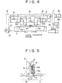
- the cutting apparatus 4 for the corrugated board web 3 shown in Fig. 3(a), Fig. 4 and Fig. 5 is provided with two sets of sprockets 9 and 10 which are fixedly mounted on an oscillating plate 8. Movable brackets 11a and 11b move in the axial direction on the surface of the oscillating plate 8. Oscillating plate 8 is pivotally mounted to a rotating frame 6 at one end thereof and is mounted to a moving frame 7 at the other end thereof.
- sprockets 12a-13a and 12b-13b are pivotally mounted on the movable brackets 11a and 11b respectively.
- An endless chain 15 having a knife 14 fixed thereto is wound between the sprockets 9 and 10 and between the sets of sprockets 12a-13a and 12b-13b as most clearly seen in Fig. 4.
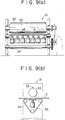
- Reference numeral 16 in Fig. 3(a) denotes a motor for pivoting the oscillating plate 8 about its axis in the running direction of the corrugated web 3, as shown by the arcuate arrow shown in Fig. 5.
- Reference numeral 17 denotes a motor for reciprocating the knife 14 across the width of the corrugated web 3 by rotating the sprocket 9 which in turn rotates the endless chain 15 having the knife 14 mounted thereon.
- a motor 36 rotates running wheels 18 mounted at the bottom of the moving frame 7 to run the moving frame 7 along a surface 20 in an arc about the supporting axis 19 of the rotating frame 6 (as shown by the arcuate arrow in Fig. 3(a)), to incline the oscillating plate 8 at a predetermined angle ⁇ relative to the width direction of the corrugated board web 3 perpendicular to the running direction of the web.
- Reference numeral 21 is an angle detecting means for detecting the swing angle ⁇ of the oscillating plate 8.
- the movable brackets 11a and 11b are constructed so as to move independently in the axial direction of the oscillating plate 8. Therefore, the knife transfer range (or cutting length) in Fig. 4 can be set by adjusting the relative distance between the brackets 11a and 11b.
- the oscillating plate 8 is pivoted about its axis by motor 16 in synchronization with the running speed of the corrugated board web 3, so as to reduce the cutting resistance of the knife 14 with respect to the corrugated board web.
- the cutting apparatus 4 is capable of cutting a transitional slit groove N in an order change region of a continuous corrugated board web 3 as shown in Fig. 1 at any desired angle and having any desired cutting length.
- the angle and length of the transitional slit groove N can be represented as a vector equal to the sum of a web running amount vector and an oscillating plate vector having an amplitude equal to the knife transfer range and an angle ⁇ equal to the angle of the plate 8 relative to the width direction of the web perpendicular to the web running direction.
- the plate 8 can be oriented at a positive angle ⁇ P in the positive web running direction or at a reverse angle ⁇ R reverse to the web running direction as shown in Fig. 3(a).
- the points P0 and R0 represent the position of the slit groove M along the web width for an existing production run prior to an order change, and the points P and R represent the new position of slit groove M for the new product order after the order change.
- the direction of the transition from the old position of groove M to the new position of groove M determines whether the plate 8 should be pivoted at a positive angle ⁇ P or a negative angle ⁇ R .
- the distance from R0 to R or from P0 to P which is known by comparing the old and new order specifications, is used as the set distance between the brackets 11a and 11b to form the knife transfer amount or range.
- the cutting length of the transitional slit groove N is a function of the web running amount, or length of web 3 passing under the plate 8, during the time that the knife 14 traverses from one of the brackets 11a or 11b to the other.
- the cutting length may be adjusted by changing either or both of the running speed of the web 3 or the speed of the motor 17 which rotates the endless belt 15. Varying the speeds during cutting of the transitional slit groove N allows any desired shape slit groove to be formed as shown in Fig. 1.
- a cutting apparatus 37 according to other embodiments of the invention is shown in Figs. 6 and 7. These embodiments use either a water jet or a laser beam in place of the knife 14 on the cutting apparatus shown in Figs. 3 through 5. Thus, the order change region between the boundaries of new and old order sheets can be separated by cutting a transitional groove in any desired shape.
- Reference numeral 38 denotes a frame for supporting an endless chain or belt 15, 39 denotes a water jet nozzle or laser beam device mounted to the chain 15, and 40 denotes a receiving member for the water jet or laser beam which is mounted under the water jet nozzle or laser beam device.
- motor 17 directly rotates the water jet nozzle or laser beam device 39 without the use of an endless belt.
- the cutting apparatus 37 for the central portion of the web 3 is operated in a real-time mode in conjunction with the conventional rotary shear 2.
Landscapes
- Life Sciences & Earth Sciences (AREA)
- Forests & Forestry (AREA)
- Engineering & Computer Science (AREA)
- Mechanical Engineering (AREA)
- Making Paper Articles (AREA)
- Machines For Manufacturing Corrugated Board In Mechanical Paper-Making Processes (AREA)
- Nonmetal Cutting Devices (AREA)
Applications Claiming Priority (3)
| Application Number | Priority Date | Filing Date | Title |
|---|---|---|---|
| JP20825/93 | 1993-01-14 | ||
| JP02082593A JP3396245B2 (ja) | 1993-01-14 | 1993-01-14 | コルゲートマシンのオーダーチェンジ方法及び装置 |
| JP2082593 | 1993-01-14 |
Publications (3)
| Publication Number | Publication Date |
|---|---|
| EP0607084A1 true EP0607084A1 (fr) | 1994-07-20 |
| EP0607084B1 EP0607084B1 (fr) | 1997-04-16 |
| EP0607084B2 EP0607084B2 (fr) | 2000-01-12 |
Family
ID=12037821
Family Applications (1)
| Application Number | Title | Priority Date | Filing Date |
|---|---|---|---|
| EP94400070A Expired - Lifetime EP0607084B2 (fr) | 1993-01-14 | 1994-01-12 | Système de modification des specifications de produit dans une machine d'ondulation |
Country Status (5)
| Country | Link |
|---|---|
| US (1) | US5496431A (fr) |
| EP (1) | EP0607084B2 (fr) |
| JP (1) | JP3396245B2 (fr) |
| AU (1) | AU655372B2 (fr) |
| DE (1) | DE69402566T3 (fr) |
Cited By (10)
| Publication number | Priority date | Publication date | Assignee | Title |
|---|---|---|---|---|
| EP0737553A1 (fr) * | 1995-04-14 | 1996-10-16 | FOSBER S.p.A. | Système pour couper et rainurer des cartons |
| DE19530025A1 (de) * | 1995-08-16 | 1997-02-20 | Ostma Maschinenbau Gmbh | Anlage für die Herstellung von Verpackungszuschnitten durch rotatives Stanzen, insbesondere für eine "Just in time"-Produktion |
| EP0999040A1 (fr) * | 1998-11-02 | 2000-05-10 | Mitsubishi Heavy Industries, Ltd. | Méthode pour changer de commande dans une machine d'ondulation |
| US6165117A (en) * | 1997-06-18 | 2000-12-26 | Fosber, S.P.A. | Device and method for the slitting of a web and slitter/scorer machine incorporating said device |
| US6553883B1 (en) | 1999-02-25 | 2003-04-29 | Fosber, S.P.A. | Apparatus for the transverse cutting of weblike material |
| US6684749B2 (en) | 2000-05-31 | 2004-02-03 | Fosber S.P.A. | Device and method for a job change in a system for the lengthwise cutting of a weblike material |
| EP1555096A3 (fr) * | 2004-01-12 | 2005-10-26 | BHS Corrugated Maschinen-und Anlagenbau GmbH | Contre-outil pour la coupe de matériaux en bande et procédé pour couper transversalement un matériau en bande avec un tel contre-outil |
| EP2075208A3 (fr) * | 2007-12-25 | 2009-07-29 | Fuji Xerox Co., Ltd. | Dispositif de traitement du papier |
| US8342068B2 (en) | 2004-10-12 | 2013-01-01 | Foser S.p.A. | Device for longitudinal cutting of a continuous web material, such as corrugated cardboard |
| ITBO20130108A1 (it) * | 2013-03-13 | 2014-09-14 | L C R Macchine Automatiche S R L | Macchina per la lavorazione di cartone in lastre o simili |
Families Citing this family (22)
| Publication number | Priority date | Publication date | Assignee | Title |
|---|---|---|---|---|
| JPH09248788A (ja) * | 1996-03-13 | 1997-09-22 | Mitsubishi Heavy Ind Ltd | コルゲートマシンのオーダチェンジ装置及び切断装置 |
| US5868056A (en) * | 1997-01-17 | 1999-02-09 | Design Systems, Inc. | Bi-directional actuator for working tool |
| US6103171A (en) * | 1998-05-11 | 2000-08-15 | Marquip, Inc. | Method and apparatus for facilitating a gapless order change in a corrugator |
| US6117381A (en) * | 1998-05-11 | 2000-09-12 | Marquip, Inc. | Method and apparatus for providing a gapless order change in a corrugator |
| US6022017A (en) * | 1998-06-02 | 2000-02-08 | Marquip, Inc. | Method for handling a small gap order change in a corrugator |
| CA2370242A1 (fr) | 2001-03-07 | 2002-09-07 | Dieter H. Hilker | Coupe-bordure a jet d'eau avec vide-bordures integre |
| US6893520B2 (en) * | 2003-01-31 | 2005-05-17 | Marquip, Llc | Method and apparatus for synchronizing end of order cutoff for a plunge slit order change on a corrugator |
| US7568411B2 (en) * | 2004-10-05 | 2009-08-04 | Marquip, Llc | Method for order transition on a plunge slitter |
| US7568412B2 (en) * | 2005-10-04 | 2009-08-04 | Marquip, Llc | Method for order transition on a plunge slitter |
| JP4718981B2 (ja) * | 2005-12-02 | 2011-07-06 | 三菱重工印刷紙工機械株式会社 | コルゲートマシンおよびこれに用いる生産管理装置 |
| JP5021438B2 (ja) * | 2007-12-05 | 2012-09-05 | レンゴー株式会社 | 段ボールシートの製造装置 |
| US20110219924A1 (en) * | 2009-07-10 | 2011-09-15 | Marquip, Llc | Method for Efficient Order Change of a Corrugator Dry End Using Order Look Ahead |
| JP5835901B2 (ja) * | 2011-01-25 | 2015-12-24 | 三菱重工印刷紙工機械株式会社 | コルゲートマシンにおけるトリム処理方法,コルゲートマシン及びエッジカット装置 |
| CN104261182B (zh) * | 2014-09-18 | 2016-08-17 | 青岛开拓数控设备有限公司 | 切边切断机、瓦楞纸板生产线及切断切边方法 |
| JP2018047655A (ja) * | 2016-09-23 | 2018-03-29 | 三菱重工機械システム株式会社 | シートの不良除去装置及び方法、シートの不良除去制御装置、段ボールシートの製造装置 |
| DE102016119281A1 (de) * | 2016-10-11 | 2018-04-12 | Windmöller & Hölscher Kg | Trennvorrichtung für das Auftrennen eines schlauchförmigen Flachmaterials, System sowie Trennverfahren |
| JP6732678B2 (ja) * | 2017-02-24 | 2020-07-29 | 三菱重工機械システム株式会社 | 段ボールウェブ裁断装置及び段ボール製造装置 |
| DE102017215712A1 (de) | 2017-09-06 | 2019-03-07 | Bhs Corrugated Maschinen- Und Anlagenbau Gmbh | Verbindungsschnittanordnung |
| IT201800003218A1 (it) * | 2018-03-02 | 2019-09-02 | Fosber Spa | Macchina taglia-cordona con sistema aspirante per rimuovere i rifili |
| JP2020138365A (ja) * | 2019-02-27 | 2020-09-03 | 三菱重工機械システム株式会社 | エッジカット装置 |
| IT202100030422A1 (it) * | 2021-12-01 | 2023-06-01 | Fosber Spa | Un dispositivo per la lavorazione longitudinale di un nastro di cartone ondulato |
| DE102024207460A1 (de) * | 2024-08-06 | 2026-02-12 | Bhs Corrugated Maschinen- Und Anlagenbau Gmbh | Schneidanordnung |
Citations (7)
| Publication number | Priority date | Publication date | Assignee | Title |
|---|---|---|---|---|
| GB2040779A (en) * | 1979-02-05 | 1980-09-03 | Astin France Assistance Tech | Cutter |
| EP0065014A1 (fr) * | 1980-11-23 | 1982-11-24 | Isowa Industry Co. Ltd. | Appareil de modification des caracteristiques d'une feuille continue de carton de fibres ondule |
| FR2529817A1 (fr) * | 1982-07-12 | 1984-01-13 | Prosymeca | Dispositif pour decouper transversalement des laies de films en defilement |
| DE3248536A1 (de) * | 1982-12-29 | 1984-07-05 | Zängl GmbH, 8000 München | Schneidvorrichtung zum schneiden von platten aus thermoplastischem material |
| JPS6133787A (ja) * | 1984-07-25 | 1986-02-17 | Mitsubishi Electric Corp | レ−ザ切断加工装置 |
| US5031496A (en) * | 1990-05-16 | 1991-07-16 | General Mills, Inc. | Apparatus and method utilizing a water jet for cutting frozen fish slabs into a plurality of individual portions |
| EP0468374A2 (fr) * | 1990-07-26 | 1992-01-29 | Mitsubishi Jukogyo Kabushiki Kaisha | Cisaille rotative |
Family Cites Families (8)
| Publication number | Priority date | Publication date | Assignee | Title |
|---|---|---|---|---|
| CH444473A (de) * | 1965-03-09 | 1967-09-30 | Firestone Prod | Vorrichtung zum Trennen von Gewebe- oder Folienbahnen zur Herstellung von Fahrzeugreifen |
| JPS542431B2 (fr) † | 1974-10-25 | 1979-02-07 | ||
| JPS542432B2 (fr) † | 1975-01-09 | 1979-02-07 | ||
| US4268341A (en) * | 1978-03-15 | 1981-05-19 | S&S Corrugated Paper Machinery Co. Inc. | Zero waste order change system for a corrugator |
| US4240856A (en) * | 1978-05-05 | 1980-12-23 | Molins Machine Company, Inc. | Continuous running corrugator |
| US4266112A (en) * | 1979-02-14 | 1981-05-05 | Niedermeyer William P | Web-cutting process |
| US4845720A (en) * | 1987-10-20 | 1989-07-04 | Matsushita Electric Industrial Co., Ltd. | Semiconductor laser control circuit |
| JP2719918B2 (ja) * | 1988-01-18 | 1998-02-25 | 株式会社ブリヂストン | シート状材料の切断装置 |
-
1993
- 1993-01-14 JP JP02082593A patent/JP3396245B2/ja not_active Expired - Fee Related
- 1993-09-28 AU AU48653/93A patent/AU655372B2/en not_active Ceased
- 1993-12-15 US US08/166,838 patent/US5496431A/en not_active Expired - Lifetime
-
1994
- 1994-01-12 DE DE69402566T patent/DE69402566T3/de not_active Expired - Lifetime
- 1994-01-12 EP EP94400070A patent/EP0607084B2/fr not_active Expired - Lifetime
Patent Citations (7)
| Publication number | Priority date | Publication date | Assignee | Title |
|---|---|---|---|---|
| GB2040779A (en) * | 1979-02-05 | 1980-09-03 | Astin France Assistance Tech | Cutter |
| EP0065014A1 (fr) * | 1980-11-23 | 1982-11-24 | Isowa Industry Co. Ltd. | Appareil de modification des caracteristiques d'une feuille continue de carton de fibres ondule |
| FR2529817A1 (fr) * | 1982-07-12 | 1984-01-13 | Prosymeca | Dispositif pour decouper transversalement des laies de films en defilement |
| DE3248536A1 (de) * | 1982-12-29 | 1984-07-05 | Zängl GmbH, 8000 München | Schneidvorrichtung zum schneiden von platten aus thermoplastischem material |
| JPS6133787A (ja) * | 1984-07-25 | 1986-02-17 | Mitsubishi Electric Corp | レ−ザ切断加工装置 |
| US5031496A (en) * | 1990-05-16 | 1991-07-16 | General Mills, Inc. | Apparatus and method utilizing a water jet for cutting frozen fish slabs into a plurality of individual portions |
| EP0468374A2 (fr) * | 1990-07-26 | 1992-01-29 | Mitsubishi Jukogyo Kabushiki Kaisha | Cisaille rotative |
Non-Patent Citations (1)
| Title |
|---|
| PATENT ABSTRACTS OF JAPAN vol. 010, no. 189 (M - 494) 3 July 1986 (1986-07-03) * |
Cited By (18)
| Publication number | Priority date | Publication date | Assignee | Title |
|---|---|---|---|---|
| US5951454A (en) * | 1995-04-14 | 1999-09-14 | Fosber S.P.A. | System for creasing and cutting sheet material such as board or the like |
| EP0737553A1 (fr) * | 1995-04-14 | 1996-10-16 | FOSBER S.p.A. | Système pour couper et rainurer des cartons |
| DE19530025A1 (de) * | 1995-08-16 | 1997-02-20 | Ostma Maschinenbau Gmbh | Anlage für die Herstellung von Verpackungszuschnitten durch rotatives Stanzen, insbesondere für eine "Just in time"-Produktion |
| US6165117A (en) * | 1997-06-18 | 2000-12-26 | Fosber, S.P.A. | Device and method for the slitting of a web and slitter/scorer machine incorporating said device |
| EP0999040A1 (fr) * | 1998-11-02 | 2000-05-10 | Mitsubishi Heavy Industries, Ltd. | Méthode pour changer de commande dans une machine d'ondulation |
| AU753644B2 (en) * | 1998-11-02 | 2002-10-24 | Mitsubishi Heavy Industries, Ltd. | Method for order changing in corrugating machines |
| US6568304B2 (en) | 1998-11-02 | 2003-05-27 | Mitsubishi Heavy Industries, Ltd. | Method for order changing in corrugating machines |
| US6722243B2 (en) | 1999-02-25 | 2004-04-20 | Fosber S.P.A. | Apparatus for the transverse cutting of weblike material |
| US6553883B1 (en) | 1999-02-25 | 2003-04-29 | Fosber, S.P.A. | Apparatus for the transverse cutting of weblike material |
| US6684749B2 (en) | 2000-05-31 | 2004-02-03 | Fosber S.P.A. | Device and method for a job change in a system for the lengthwise cutting of a weblike material |
| EP1555096A3 (fr) * | 2004-01-12 | 2005-10-26 | BHS Corrugated Maschinen-und Anlagenbau GmbH | Contre-outil pour la coupe de matériaux en bande et procédé pour couper transversalement un matériau en bande avec un tel contre-outil |
| CN1640634B (zh) * | 2004-01-12 | 2010-05-05 | Bhs波纹纸加工机械及设备有限公司 | 带状材料切割装置及在带状材料中产生横向切口的方法 |
| US8342068B2 (en) | 2004-10-12 | 2013-01-01 | Foser S.p.A. | Device for longitudinal cutting of a continuous web material, such as corrugated cardboard |
| EP2075208A3 (fr) * | 2007-12-25 | 2009-07-29 | Fuji Xerox Co., Ltd. | Dispositif de traitement du papier |
| US8266995B2 (en) | 2007-12-25 | 2012-09-18 | Fuji Xerox Co., Ltd. | Paper processing device |
| CN101468474B (zh) * | 2007-12-25 | 2013-04-24 | 富士施乐株式会社 | 纸张处理装置 |
| ITBO20130108A1 (it) * | 2013-03-13 | 2014-09-14 | L C R Macchine Automatiche S R L | Macchina per la lavorazione di cartone in lastre o simili |
| EP2777899A1 (fr) * | 2013-03-13 | 2014-09-17 | L.C.R. Macchine Automatiche S.R.L. | Dispositif pour la laboration des poses |
Also Published As
| Publication number | Publication date |
|---|---|
| AU4865393A (en) | 1994-07-21 |
| JP3396245B2 (ja) | 2003-04-14 |
| EP0607084B2 (fr) | 2000-01-12 |
| JPH06210772A (ja) | 1994-08-02 |
| DE69402566T2 (de) | 1997-07-24 |
| AU655372B2 (en) | 1994-12-15 |
| EP0607084B1 (fr) | 1997-04-16 |
| US5496431A (en) | 1996-03-05 |
| DE69402566T3 (de) | 2001-02-15 |
| DE69402566D1 (de) | 1997-05-22 |
Similar Documents
| Publication | Publication Date | Title |
|---|---|---|
| EP0607084B1 (fr) | Système de modification des specifications de produit dans une machine d'ondulation | |
| AU626759B2 (en) | Rotary shear | |
| EP0894583B1 (fr) | Machine pour la coupe longitudinale et le rainurage équipée d'outils indépendants ainsi que méthode correspondante pour le changement de format | |
| EP0534177B1 (fr) | Cisaille rotative | |
| US5348527A (en) | Apparatus for cutting and stacking a multi-form web | |
| EP0449006A2 (fr) | Dispositif et procÀ©dé pour découper des bandes | |
| DE69532531T2 (de) | Gerät zum wenden und zum hintereinander angeordnet bereitstellen von bogenmaterial und entsprechendes verfahren | |
| US4871157A (en) | Zigzag folding apparatus having web cutter means | |
| JPS6142703B2 (fr) | ||
| US5050812A (en) | Dual-envelope making machine and method of using | |
| US4727784A (en) | Web cut blank piling method and apparatus | |
| US6893520B2 (en) | Method and apparatus for synchronizing end of order cutoff for a plunge slit order change on a corrugator | |
| EP3932634B1 (fr) | Dispositif de coupe de bord | |
| AU620758B2 (en) | Slitterscorer | |
| US6117381A (en) | Method and apparatus for providing a gapless order change in a corrugator | |
| EP0795382A2 (fr) | Appareil pour changer de commande et dispositif de coupe pour une machine d'ondulation | |
| KR19980081283A (ko) | 절단 나이프에서 절단 시트들을 직접 싱글링하는 방법 및 장치 | |
| US6669617B1 (en) | Paper web folding and cutting apparatus | |
| US5049117A (en) | Dual-envelope making machine and method of using | |
| US5346195A (en) | Apparatus and method for indexing sheets | |
| JP3540742B2 (ja) | 段ボールシート処理装置及び段ボールシート処理方法 | |
| KR20010092310A (ko) | 두 외층 사이에 경질 발포 코어가 배치된 연속 제조 압출패널로부터 한정된 길이의 구획을 제거하는 방법 및 톱질장치 | |
| JP5457905B2 (ja) | 段ボールシートの切断方法及び装置 | |
| JPH0657397B2 (ja) | 板紙溝切り装置 | |
| JPH0569390A (ja) | 回転ドラム式切断装置 |
Legal Events
| Date | Code | Title | Description |
|---|---|---|---|
| PUAI | Public reference made under article 153(3) epc to a published international application that has entered the european phase |
Free format text: ORIGINAL CODE: 0009012 |
|
| AK | Designated contracting states |
Kind code of ref document: A1 Designated state(s): CH DE FR GB IT LI NL |
|
| 17P | Request for examination filed |
Effective date: 19940826 |
|
| 17Q | First examination report despatched |
Effective date: 19960131 |
|
| GRAG | Despatch of communication of intention to grant |
Free format text: ORIGINAL CODE: EPIDOS AGRA |
|
| GRAH | Despatch of communication of intention to grant a patent |
Free format text: ORIGINAL CODE: EPIDOS IGRA |
|
| GRAH | Despatch of communication of intention to grant a patent |
Free format text: ORIGINAL CODE: EPIDOS IGRA |
|
| GRAA | (expected) grant |
Free format text: ORIGINAL CODE: 0009210 |
|
| AK | Designated contracting states |
Kind code of ref document: B1 Designated state(s): CH DE FR GB IT LI NL |
|
| ET | Fr: translation filed | ||
| REG | Reference to a national code |
Ref country code: CH Ref legal event code: NV Representative=s name: IPTO S.A. Ref country code: CH Ref legal event code: EP |
|
| REF | Corresponds to: |
Ref document number: 69402566 Country of ref document: DE Date of ref document: 19970522 |
|
| PLBQ | Unpublished change to opponent data |
Free format text: ORIGINAL CODE: EPIDOS OPPO |
|
| PLBI | Opposition filed |
Free format text: ORIGINAL CODE: 0009260 |
|
| PLBF | Reply of patent proprietor to notice(s) of opposition |
Free format text: ORIGINAL CODE: EPIDOS OBSO |
|
| 26 | Opposition filed |
Opponent name: FOSBER S.P.A. Effective date: 19980113 |
|
| NLR1 | Nl: opposition has been filed with the epo |
Opponent name: FOSBER S.P.A. |
|
| PLBF | Reply of patent proprietor to notice(s) of opposition |
Free format text: ORIGINAL CODE: EPIDOS OBSO |
|
| PLBF | Reply of patent proprietor to notice(s) of opposition |
Free format text: ORIGINAL CODE: EPIDOS OBSO |
|
| PLAW | Interlocutory decision in opposition |
Free format text: ORIGINAL CODE: EPIDOS IDOP |
|
| PLAW | Interlocutory decision in opposition |
Free format text: ORIGINAL CODE: EPIDOS IDOP |
|
| PUAH | Patent maintained in amended form |
Free format text: ORIGINAL CODE: 0009272 |
|
| STAA | Information on the status of an ep patent application or granted ep patent |
Free format text: STATUS: PATENT MAINTAINED AS AMENDED |
|
| 27A | Patent maintained in amended form |
Effective date: 20000112 |
|
| AK | Designated contracting states |
Kind code of ref document: B2 Designated state(s): CH DE FR GB IT LI NL |
|
| ET3 | Fr: translation filed ** decision concerning opposition | ||
| REG | Reference to a national code |
Ref country code: CH Ref legal event code: AEN Free format text: MAINTIEN DU BREVET DONT L'ETENDUE A ETE MODIFIEE |
|
| NLR2 | Nl: decision of opposition | ||
| ITF | It: translation for a ep patent filed | ||
| NLR3 | Nl: receipt of modified translations in the netherlands language after an opposition procedure | ||
| REG | Reference to a national code |
Ref country code: DE Ref legal event code: 8570 |
|
| REG | Reference to a national code |
Ref country code: GB Ref legal event code: IF02 |
|
| PGFP | Annual fee paid to national office [announced via postgrant information from national office to epo] |
Ref country code: CH Payment date: 20030116 Year of fee payment: 10 |
|
| PGFP | Annual fee paid to national office [announced via postgrant information from national office to epo] |
Ref country code: NL Payment date: 20030130 Year of fee payment: 10 |
|
| PG25 | Lapsed in a contracting state [announced via postgrant information from national office to epo] |
Ref country code: LI Free format text: LAPSE BECAUSE OF NON-PAYMENT OF DUE FEES Effective date: 20040131 Ref country code: CH Free format text: LAPSE BECAUSE OF NON-PAYMENT OF DUE FEES Effective date: 20040131 |
|
| PG25 | Lapsed in a contracting state [announced via postgrant information from national office to epo] |
Ref country code: NL Free format text: LAPSE BECAUSE OF NON-PAYMENT OF DUE FEES Effective date: 20040801 |
|
| REG | Reference to a national code |
Ref country code: CH Ref legal event code: PL |
|
| NLV4 | Nl: lapsed or anulled due to non-payment of the annual fee |
Effective date: 20040801 |
|
| PGFP | Annual fee paid to national office [announced via postgrant information from national office to epo] |
Ref country code: GB Payment date: 20080109 Year of fee payment: 15 |
|
| PGFP | Annual fee paid to national office [announced via postgrant information from national office to epo] |
Ref country code: FR Payment date: 20080108 Year of fee payment: 15 |
|
| GBPC | Gb: european patent ceased through non-payment of renewal fee |
Effective date: 20090112 |
|
| REG | Reference to a national code |
Ref country code: FR Ref legal event code: ST Effective date: 20091030 |
|
| PG25 | Lapsed in a contracting state [announced via postgrant information from national office to epo] |
Ref country code: GB Free format text: LAPSE BECAUSE OF NON-PAYMENT OF DUE FEES Effective date: 20090112 |
|
| PG25 | Lapsed in a contracting state [announced via postgrant information from national office to epo] |
Ref country code: FR Free format text: LAPSE BECAUSE OF NON-PAYMENT OF DUE FEES Effective date: 20090202 |
|
| PGFP | Annual fee paid to national office [announced via postgrant information from national office to epo] |
Ref country code: IT Payment date: 20120118 Year of fee payment: 19 |
|
| PGFP | Annual fee paid to national office [announced via postgrant information from national office to epo] |
Ref country code: DE Payment date: 20130109 Year of fee payment: 20 |
|
| REG | Reference to a national code |
Ref country code: DE Ref legal event code: R071 Ref document number: 69402566 Country of ref document: DE |
|
| REG | Reference to a national code |
Ref country code: DE Ref legal event code: R071 Ref document number: 69402566 Country of ref document: DE |
|
| PG25 | Lapsed in a contracting state [announced via postgrant information from national office to epo] |
Ref country code: DE Free format text: LAPSE BECAUSE OF EXPIRATION OF PROTECTION Effective date: 20140114 |