EP0607416B1 - Verpackungselement, insbesondere zur verpackung und zum transport von einem stapel druckerzeugnisse, wie zeitungen, zeitschriften, büchern, prospekten, katalogen oder ähnlichen - Google Patents
Verpackungselement, insbesondere zur verpackung und zum transport von einem stapel druckerzeugnisse, wie zeitungen, zeitschriften, büchern, prospekten, katalogen oder ähnlichen Download PDFInfo
- Publication number
- EP0607416B1 EP0607416B1 EP93918888A EP93918888A EP0607416B1 EP 0607416 B1 EP0607416 B1 EP 0607416B1 EP 93918888 A EP93918888 A EP 93918888A EP 93918888 A EP93918888 A EP 93918888A EP 0607416 B1 EP0607416 B1 EP 0607416B1
- Authority
- EP
- European Patent Office
- Prior art keywords
- packaging element
- fixing
- element according
- packaging
- fabric
- Prior art date
- Legal status (The legal status is an assumption and is not a legal conclusion. Google has not performed a legal analysis and makes no representation as to the accuracy of the status listed.)
- Expired - Lifetime
Links
- 238000004806 packaging method and process Methods 0.000 title claims abstract description 137
- 239000000463 material Substances 0.000 title claims abstract description 30
- 230000003014 reinforcing effect Effects 0.000 claims abstract description 13
- 239000004744 fabric Substances 0.000 claims description 35
- 239000004033 plastic Substances 0.000 claims description 5
- 229920003023 plastic Polymers 0.000 claims description 5
- 229920000742 Cotton Polymers 0.000 claims description 4
- 229920001875 Ebonite Polymers 0.000 claims description 3
- 239000005871 repellent Substances 0.000 claims description 3
- 239000002023 wood Substances 0.000 claims description 3
- 240000000491 Corchorus aestuans Species 0.000 claims description 2
- 235000011777 Corchorus aestuans Nutrition 0.000 claims description 2
- 235000010862 Corchorus capsularis Nutrition 0.000 claims description 2
- 229910052751 metal Inorganic materials 0.000 claims description 2
- 239000002184 metal Substances 0.000 claims description 2
- 238000012856 packing Methods 0.000 claims description 2
- 229920002994 synthetic fiber Polymers 0.000 claims description 2
- 239000000835 fiber Substances 0.000 claims 1
- 230000002787 reinforcement Effects 0.000 description 13
- 238000000034 method Methods 0.000 description 8
- 239000005022 packaging material Substances 0.000 description 7
- 238000013461 design Methods 0.000 description 4
- 238000004519 manufacturing process Methods 0.000 description 4
- 238000012858 packaging process Methods 0.000 description 4
- 239000002985 plastic film Substances 0.000 description 3
- 229920006255 plastic film Polymers 0.000 description 3
- 229910000639 Spring steel Inorganic materials 0.000 description 2
- 229910052782 aluminium Inorganic materials 0.000 description 2
- XAGFODPZIPBFFR-UHFFFAOYSA-N aluminium Chemical compound [Al] XAGFODPZIPBFFR-UHFFFAOYSA-N 0.000 description 2
- 230000007423 decrease Effects 0.000 description 2
- 239000002699 waste material Substances 0.000 description 2
- 208000027418 Wounds and injury Diseases 0.000 description 1
- 235000013361 beverage Nutrition 0.000 description 1
- 230000015572 biosynthetic process Effects 0.000 description 1
- 238000001514 detection method Methods 0.000 description 1
- 238000011161 development Methods 0.000 description 1
- 238000005265 energy consumption Methods 0.000 description 1
- 238000005516 engineering process Methods 0.000 description 1
- 239000011888 foil Substances 0.000 description 1
- 230000001771 impaired effect Effects 0.000 description 1
- 208000014674 injury Diseases 0.000 description 1
- 239000000203 mixture Substances 0.000 description 1
- 238000012536 packaging technology Methods 0.000 description 1
- 239000010893 paper waste Substances 0.000 description 1
- 239000002994 raw material Substances 0.000 description 1
- 238000004064 recycling Methods 0.000 description 1
- 239000012209 synthetic fiber Substances 0.000 description 1
- 238000012360 testing method Methods 0.000 description 1
Images


Classifications
-
- B—PERFORMING OPERATIONS; TRANSPORTING
- B65—CONVEYING; PACKING; STORING; HANDLING THIN OR FILAMENTARY MATERIAL
- B65D—CONTAINERS FOR STORAGE OR TRANSPORT OF ARTICLES OR MATERIALS, e.g. BAGS, BARRELS, BOTTLES, BOXES, CANS, CARTONS, CRATES, DRUMS, JARS, TANKS, HOPPERS, FORWARDING CONTAINERS; ACCESSORIES, CLOSURES, OR FITTINGS THEREFOR; PACKAGING ELEMENTS; PACKAGES
- B65D75/00—Packages comprising articles or materials partially or wholly enclosed in strips, sheets, blanks, tubes or webs of flexible sheet material, e.g. in folded wrappers
- B65D75/04—Articles or materials wholly enclosed in single sheets or wrapper blanks
- B65D75/14—Articles or materials wholly enclosed in single sheets or wrapper blanks in sheets or blanks folded-up around all sides of the contents from a portion on which the contents are placed
-
- A—HUMAN NECESSITIES
- A45—HAND OR TRAVELLING ARTICLES
- A45C—PURSES; LUGGAGE; HAND CARRIED BAGS
- A45C7/00—Collapsible or extensible purses, luggage, bags or the like
- A45C7/0059—Flexible luggage; Hand bags
- A45C7/0095—Flexible luggage; Hand bags comprising a plurality of hinged panels to be unfolded in one plane for access purposes
-
- B—PERFORMING OPERATIONS; TRANSPORTING
- B65—CONVEYING; PACKING; STORING; HANDLING THIN OR FILAMENTARY MATERIAL
- B65D—CONTAINERS FOR STORAGE OR TRANSPORT OF ARTICLES OR MATERIALS, e.g. BAGS, BARRELS, BOTTLES, BOXES, CANS, CARTONS, CRATES, DRUMS, JARS, TANKS, HOPPERS, FORWARDING CONTAINERS; ACCESSORIES, CLOSURES, OR FITTINGS THEREFOR; PACKAGING ELEMENTS; PACKAGES
- B65D2313/00—Connecting or fastening means
- B65D2313/02—Connecting or fastening means of hook-and-loop type
Definitions
- the invention relates to a packaging element, in particular for packaging and transporting a stack of printed products, such as newspapers, magazines, books, brochures, catalogs or the like, according to the preamble of claim 1.
- the filled packaging element is provided with a labeled sticker with the address of the newspaper dealer or newspaper messenger and delivered.
- the filled packaging element When the filled packaging element has reached its destination, it is opened for the removal of the newspapers or magazines by tearing or cutting the tape material and the plastic wrapping. The newspapers are then removed and the packaging material is thrown away.
- a collapsible container for holding objects in particular a school bag for carrying books is known, which consists of a light, flexible, relatively tough and relatively strong material.
- This container has a central field and two pairs of flaps lying opposite one another and consisting of one piece with the central field.
- the inner surfaces of a flap and the outer surfaces of the flap opposite each other are provided with interacting, releasably interlocking connecting means to hold the flaps together when one flap is placed on the other flap arranged opposite it when it is driven in.
- a foldable transport container made of cardboard for objects, in particular beverage cans is known, the objects to be transported being wrapped in a belt.
- This belt takes up the weight of the objects during transport, so that the transport container is relieved.
- the strap is led out through slots in the transport container and serves as a handle element. When carrying by means of the handle element, the packaging is not supported, but the objects, while the packaging itself rests on the objects.
- the invention has for its object to provide a reusable packaging element that enables both a manual and a simple mechanical, tight and firm fixation of a stack of printed products, as well as facilitating the handling and transportation of the stack of printed products.
- the special cut of the packaging element the connection of the individual sections of the cut to their structure with mostly detachable fastening means and the choice of the packaging material enables reusability and both mechanical and manual fixing of printed products and ensures their optimal protection against damage, particularly during transport, as explained in more detail below becomes.
- the packaging element according to the invention consists of a tear-resistant fabric or film material. This material prevents the packaging element from being destroyed during mechanical or manual assembly and disassembly and during transport by impact and friction forces. This material also ensures that the packaging element is extremely flexible. The flexibility reduces the wear of the packaging element with frequent use and is also important for a simple mechanical or manual wrapping of the newspapers. In particular, due to the flexibility of the material, the packaging element can be folded up without damage and even compressed. This allows space-saving collection and easy return of the packaging element to the print shop.
- the flexibility of the packaging element also has the advantage that, for example, a slight exceeding of the stack height of the packaged goods is problem-free both in a mechanical and in a manual packaging process. For example, no package height detection is required. Thanks to its locking technology, the packaging element reacts to you absolutely independently of the control system large range of stacking heights of the printed products to be packed. During production, the packaging element can be modified for the user in any format, taking into account the possible minima or maxima, based on experience with packaging technology.
- the blank of the packaging element has an approximately rectangular receiving surface for the stack of printed products, on the four side edges of which a fixing surface for fixing the stack of printed products is pivotally arranged.
- the packaging element can easily be assembled and closed by swiveling the fixing surfaces after filling with printed products.
- the newspaper seller who receives a stack of newspapers packaged in this way, only needs a few simple steps for loosening and pivoting away the fixing surfaces associated with predominantly releasable fastening means in the packaging element placed on the underside of the receiving surface until he can remove the printed products from the packaging element. Due to the attachment of the releasable fastening means, the packaging element cannot open and remove the printed products to be damaged.
- the fixing surfaces are subdivided into side surfaces and top surfaces, the top surfaces at least partially overlapping when the packaging element is closed.
- a further side surface is arranged on the top surface of the fixing surface to be folded up last when closing, which in the filled state of the packaging element can always be fastened to the side surface of the opposite fixing surface via releasable fastening means.
- the inside of the two last fixing surfaces to be folded up as well as the receiving surface carry a continuous, centrally arranged reinforcement tape which is glued on and / or braided.
- the reinforcing tape in the area of the outer fixing surface is expediently braided into the side surface and head surface in such a way that it forms grip elements on the outside of the head surface of the fixing surface that has to be folded up last.
- the side surface adjoining the associated head surface and the further side surface are only loaded in the longitudinal direction of their surface, so that their fastening means do not detach themselves can and, consequently, cannot lift off the head surface provided with the grip elements.
- the reinforcement band can also step out on the side surface of the last fixing surface to be folded up and form a grip element.
- the handle elements serve for injury-free handling when removing the parcel from the conveyor belt and further transport.
- the packaging element can thus be easily carried and handled on the handle elements, with the continuous, centrally arranged reinforcement band supporting the packaging element on the lateral and lower surfaces in the carried position.
- the passage points of the reinforcing tape can be reinforced on the side surface and / or on the top surface.
- round bars arranged as reinforcements at the passage points of the reinforcement tape serve as reinforcements, which are arranged parallel to the passage points and underneath the head surface and overlap the reinforcement tape.
- the passage points therefore tear even with a long rough Do not use and the round bars parallel to the passage points serve as a tensile load abutment and distribute the load over a larger area of the fixing surfaces.
- the fixing surfaces can have a rectangular, trapezoidal, triangular surface shape or a combination of these surface shapes. Furthermore, the fixing surfaces can be designed and arranged symmetrically or asymmetrically with respect to the side bisectors of the receiving surface. In addition, the fixing surfaces can have the same or different surface shapes.
- the respective selection of the forms is made according to aspects such as protection of the printed products against mechanical damage or weather influences as well as empty weight and material expenditure of the packaging element.
- a version with rectangular fixing surfaces is preferred, which completely encase the stack of newspapers and thus offer protection against the weather.
- the fixing surfaces can be designed as narrow straps.
- Films and fabrics are suitable as the material for the packaging element, natural fabric such as cotton fabric, cotton blend fabric, jute fabric, synthetic fiber fabric or a combination of these materials being used as the fabric material.
- the fabric material can be treated to be water-repellent, impregnated or coated.
- the fixing surfaces can consist of a stretchable material, preferably a mesh-like fabric or grid fabric.
- This configuration is particularly expedient if packaging elements of uniform size are to be used for packaging stacks with a considerably varying stack height. As the inherent stability of a stack decreases with increasing stack height, the fixing forces of the packaging element decrease with increasing elongation to, so that good stability of the filled and closed packaging element is always achieved.
- the invention provides that the packaging element is composed of two intersecting fabric webs.
- the packaging element can be machined from commercially available webs of rolls without requiring a special cut.
- the double position of the fabric webs in the area of the receiving surface results in a desired increased rigidity and stability.
- Velcro fasteners are preferably used as releasable fastening means.
- two Velcro strips are arranged along the side edges of the head surfaces, the head surfaces to be attached to one another alternately carrying the interlocking Velcro strips on their top and on their underside.
- the Velcro fasteners enable the mechanical or manual rollover of the fixing surfaces or the head surfaces and their connection, as well as the closing of the packaging element in one work phase can be.
- the opposite arrangement of two Velcro straps or fleece straps is advantageously designed such that e.g. when the empty packaging elements are stacked, no Velcro strips come into contact with the fleece strips of a packaging element below or above. The removal of the empty packaging element e.g. to the filling station or the conveyor belt is thus carried out without any problems.
- this configuration enables the head surfaces to be optimally fastened to one another without the opening of the packaging element becoming difficult.
- a further Velcro strip is arranged on the top of the head surface of the fixing surface to be folded up as the second, near the side edge facing the last fixing surface to be folded up and the underside of the head surface to be fastened thereon as the third fixing surface to be folded up.
- This configuration enables a fixing surface or a section of the fixing surface to be used for removal but also for filling newspapers or magazines Pocket flap can be designed to be pivotable without the stability being significantly impaired.
- the packaging element can optionally be used simultaneously as a newspaper bag for delivering newspapers by a newspaper deliverer, or can be used as an open bag in the bicycle transport bag or in a car.
- a further embodiment of the invention provides that weighting elements, preferably rounded flat bars, are incorporated at least in each case on the outermost side edge of the head surface.
- This design firstly weighs down the head surfaces at their side ends and, secondly, brings about a linear guidance of the packaging element sides during the mechanical or manual assembly of the packaging element by a packaging machine or by hand.
- the weighting elements which are made of spring steel or aluminum, for example, can be inserted into a hemstitch prepared for this purpose.
- Valuable magazines can also be transported in the packaging element according to the invention protected from buckling.
- the increased stability is particularly important when the packaging element is used as a bag.
- feet are arranged on the back of the receiving surface. These can be placed in such a way that they rest on the weighting elements when stacking filled packaging elements.
- the packaging elements can be placed on the receiving surface without getting dirty. Furthermore, stacking of the packaged newspapers is now possible, in which the individually filled packaging elements cannot slip against one another.
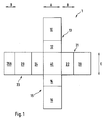
- Fig. 1 shows a schematic representation of a blank of a packaging element 1, which consists of a tear-resistant fabric or film material and has a rectangular receiving surface 40 for the newspapers or magazines.
- a rectangular fixing surface 13, 15, 21, 23 is pivotably arranged on each of the four side edges of the rectangular receiving surface 40.
- Each fixing surface 13, 15, 21, 23 consists of a side surface 12, 14, 22, 24, which is slightly higher than the height of the stack of newspapers to be wrapped, and a head surface 10, 16, 20, 26 which is pivotally arranged thereon, and a further side surface 26A.
- the receiving surface 40 is provided for supporting the newspapers or magazines, ie the size of the surface 40 with the side length A and C (see arrows A, C in Fig. 1) corresponds to the contact surface of the newspapers or magazines to be filled. As will be explained later, this results in a simple mechanical filling of the packaging element 1 by stacking the newspapers or magazines on the receiving surface 40.
- the head surfaces 10, 16, 20, 26 are of the same size as the receiving surface 40 (see arrows A, C in FIG. 1). This results in an optimal wrapping of the stack of newspapers or magazines. In addition, the stability of the packaging element 1 increases, which is particularly important for the use of the packaging element 1 as a bag.
- the packaging element 1 consists of a tear-resistant fabric material, which has been used for a long time for the production of newspaper transport bags, which are often used almost daily for many years and in all weather conditions, and has proven itself extremely well there.
- a special plastic film could also be used.
- the fabric prevents the packaging element 1 from being destroyed during mechanical assembly and disassembly and during transport by impact and friction forces. It also ensures a high degree of flexibility of the packaging element 1.
- the flexibility of the packaging element 1 reduces the wear which inevitably occurs when used frequently.
- the flexibility is also for a simple machine or manual wrapping the packaging element 1 important, as will be explained later.
- the packaging element 1 can be folded together without damage due to the fabric flexibility of the material, and can even be compressed. In this way, the packaging elements can be collected in a space-saving manner and later brought to the print shop.
- the cut of the packaging element 1 shown here is formed in the simplest way only by crossing the fabric webs 2 and 3.
- the outside of the fabric webs 2, 3 is water-repellent, so that no moisture can penetrate into the packaging element 1 when the packaging element 1 is being transported.
- the fabric webs 2 and 3 are sewn, riveted, glued or welded to one another in their overlap region which forms the receiving surface 40 for the newspapers or magazines to be stacked, so that the individual fixing surfaces 13, 15, 21, are located on the four side edges of the receiving surface 40. 23 train.
- FIGS. 2 and 3 show a schematic illustration of a blank of a packaging element from FIG. 1, FIG. 2 illustrating the arrangement of Velcro strips 50-59, while FIG. 3 shows the arrangement of a reinforcing strip 61 that is partially braided into the fixing surfaces.
- packaging element 1 The various important details of the packaging element 1 are described below with reference to FIGS. 2 and 3.
- the points on the receiving surface 40 indicate the position of the feet, which can lie against the flat bars 41, 42, 43 described in the stacking of two filled packaging elements 1. This makes it possible to stack the packaged newspapers, in which the individual filled packaging elements 1 cannot slip against one another. Furthermore, the packaging element 1 can be placed on the back of the receiving surface 40 without becoming soiled.
- the receiving surface 40 can additionally be reinforced by a plate made of plastic, hard rubber or wood (not shown). This increases the stability of the packaging element 1.
- the reinforcing plate can be fastened to the receiving surface 40 with fastening elements which are designed as feet on the rear of the receiving surface 40.
- the reinforcement plate can be attached to the fabric or film material in one step with the attachment of the feet.
- the feet are attached to the reinforcement plate extremely durable.
- Velcro fasteners 50 to 59 are arranged as fastening means.
- the Velcro fasteners 50 to 59 enable the mechanical or manual rollover of the fixing surfaces 13, 15, 21, 23 or the head surfaces 10, 16, 20, 26 and the further side surface 26A and their connection, as well as the closing of the packaging element in one Work phase can be carried out.
- the Velcro fasteners 51 to 59 are designed as Velcro strips 51 to 59, wherein two Velcro strips are arranged along the side edges of the head surfaces 10, 16, 20, 22, 26 and the further side surface 26A.
- the head surfaces 10, 16, 20, 26 to be arranged on one another, the side surface 22 and the further side surface 26A carry the interlocking Velcro strips 51 to 59 alternately on their adjoining upper and lower sides, so that when the head surfaces 10, 16, 20, 26 and the side surface 22 engage with the other side surface 26A.
- Flat bars 41, 42, 43, 44 are incorporated in each case on the outermost side edge of the head surfaces 10, 16, 20 and the side surface 26A.
- the flat surfaces 41, 42, 43, 44 weigh down the top surfaces 10, 16, 20 and the further side surface 26A in such a way that both a simplification of the mechanical structure and a linear closure of the packaging element 1 by a packaging machine result.
- the flat bars 41, 42, 43, 44 which consist, for example, of spring steel or aluminum, can be inserted into a hemstitch prepared for this purpose.
- the flat bars are 1 to 3 mm thick, so that they cannot bend in the case of a planned, mechanical or manual assembly.
- the flat bars 41, 42, 43, 44 are rounded so as not to destroy the tissue due to sharp edges.
- the fixing surfaces 21 and 23 as well as the receiving surface 40 carry a continuous, centrally arranged reinforcement band 61.
- the fixing surfaces 21 and 23 are those which, when closed, are on the outside.
- the reinforcing tape 61 is braided into the side surface 24 and the top surface 26 in such a way that it is on the outside of the Side surface 24 and the top surface 26 forms grip elements 62, 63.
- the passage points 64, 65 of the reinforcing tape 61 are reinforced on the side surface 24 and on the top surface 26. Round rods 66 parallel to the passage points 64 overlap the reinforcement band 61 and under the head surfaces 26.
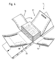
- a packaging element 1 the cut of which consists of a rectangular receiving surface 40 with rectangular fixing surfaces 13, 15, 21, 23 pivotably arranged on the side edges, with the underside of its rectangular receiving surface 40 on a transport unit of a packaging device (FIG. 4 ) was launched and then filled with newspapers or magazines.
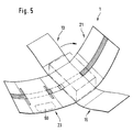
- FIGS. 4 and 5 show the packaging element 1 with the fixing surfaces 13, 15, 21, 23 and one with the reference symbol 60 labeled address label (transport code / packing slip or similar) arranged on the upper side of the fixing surface 23 and indicated by dashed lines on the underside of the packaging element shown. 4 and 5 differ only in that, for the sake of clarity, the Velcro strips 50-59 are shown in FIG. 4 and the reinforcement tape 61 is shown in FIG. 5. In the following representations, the Velcro strips 50-59 and the reinforcement band 61 are drawn in together.
- the tool element corresponding to the fixing surface 13 (not visible in the figure) is activated.
- the tool element moves the fixing surface 13 in the direction of the arrow over the stack of newspapers.
- the next process step is explained with reference to FIG. 7.
- the tool element belonging to the fixing surface 21 is activated (not visible). It moves the fixing surface 21 around the partially already wrapped newspaper stack in the direction of the arrow, so that the Velcro on the underside of the fixing surface 21 and the Velcro on the top of the fixing surface 15 automatically engage when the fixing surface 21 sinks, whereby the fixing surfaces are connected to one another.
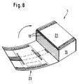
- the tool element corresponding to the fixing surface 23, which moves the fixing surface 23 around the stack of newspapers in the direction of the arrow is activated in a subsequent method step, which is shown in FIG. 8.
- the Velcro strips on the upper side of the fixing surface 21 and on the lower side of the fixing surface 23 interlock and close the packaging element 1.
- each fixing surface 13, 15, 21, 23 around the Stack of newspapers to be pivoted.
- the swiveling process enables a simple packaging process in which complicated movements of the tool elements are eliminated.
- the address label 60 is visibly arranged on the top of the packaging element 1.
- the packaging element for removing the newspapers can be placed on its side surface 22 and opened by swiveling away the fixing surface provided for this while loosening the Velcro fasteners and thus used as a newspaper pocket.
- Handle elements 62, 63 arranged on the packaging element 1 can further increase the manageability of such a newspaper pocket.
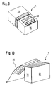
- FIG. 11 shows a completely filled and closed packaging element on a conveyor belt.
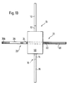
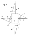
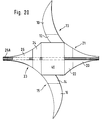
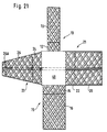
- FIGS. 12 to 21 show further design options for a packaging element blank. Shown are the receiving surface 40, the fixing surfaces 13, 15, 21 and 23 as well as the side surfaces 12, 14, 22 dividing the fixing surfaces 13, 15, 21 and 23, 24, top surfaces 10, 16, 20, 26 and the further side surface 26A.
- the boundaries between the head surfaces 10, 16, 20, 26 on the one hand and the side surfaces 12, 14, 22, 24 and the further side surface 26A on the other hand are not strictly specified, but can vary somewhat depending on the stack height.
- the fixing surfaces in the illustration according to FIG. 12 are formed by the combination of two rectangles of different widths.
- the rectangular partial surfaces adjoining the receiving surface 40 extend completely over the side edges of the receiving surface 40 and the further rectangular partial surfaces are reduced to the width of narrow belts.
- all fixing surfaces 13, 15, 21, 23 are designed as narrow belts and only adjoin a part of the side edge of the receiving surface 40. It is also possible to dimension the fixing surfaces 13 and 15 on the one hand and the fixing surfaces 21 and 23 on the other hand in different widths.
- the fixing surfaces 13, 15, 21 and 23 present a combined trapezoidal and rectangular shape.
- the trapezoidal partial surfaces completely adjoin the side edges of the receiving surface 40 and rectangular narrow partial surfaces adjoin the narrower edges of the trapezoidal partial surfaces.
- the fixing surfaces are formed by the combination of trapezoidal partial surfaces with rectangular partial surfaces and by the combination of different trapezoidal partial surfaces.
- a trapezoidal partial surface adjoins the receiving surface 40, the trapezoidal partial surface, however, only partially extending along the side edge of the receiving surface 40.
- Rectangular narrow partial surfaces adjoin the narrower edges of the trapezoidal partial surfaces.
- the fixing surface 23 consists of a first trapezoidal partial surface which is completely adjacent to the side edge of the receiving surface 40 and a second trapezoidal partial surface which is adjacent to the narrower edge of the first trapezoidal partial surface.
- the fixing surface 21 comprises a completely along the side edge of the receiving surface 40 adjoining this rectangular partial surface and a trapezoidal partial surface adjoining the rectangular partial surface.
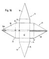
- FIG. 16 shows an embodiment in which the fixing surfaces 13, 15, 21 and 23 present a combined rectangular and triangular shape.
- rectangular partial surfaces completely adjoin the receiving surface 40 along the side edge thereof, and triangular partial surfaces adjoin the rectangular partial surfaces.
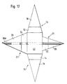
- all fixing surfaces 13, 15, 21 and 23 have an isosceles triangular shape.
- the fixing surfaces 13, 15 and 23 extend completely along the side edge of the receiving surface 40, but the fixing surface 21 only partially.
- the fixing surfaces 13, 15, 21 and 23 of the embodiment shown in FIG. 18 also have a triangular shape, but not an isosceles triangular shape. Rather, the triangles are arranged asymmetrically to the side bisector of the respective side edge of the receiving surface 40 and extend only over a partial area of the respective side edge.
- the fixing 19 comprises two fixing surfaces 13 and 15 in an isosceles triangular shape and two further fixing surfaces 21 and 23, each with two opposite straight edges and two opposite concavely shaped edges. While the fixing surfaces 15 and 21 extend completely along the side edge of the receiving surface 40, the fixing surfaces 13 and 23 extend only over a partial area of the respective side edge.
- the embodiment shown in FIG. 20 comprises two fixing surfaces 21 and 23, each with two opposite straight edges and two opposite concave edges.
- the outer straight edges are shorter than the other, so that the fixing surfaces 21 and 23 taper outwards.
- Two further fixing surfaces 13 and 15 form a sickle shape and consist of a straight edge, which extends partially along the side edge of the receiving surface 40, and a concave and a convex edge, which form a tip on the outside.
- FIG. 21 shows a packaging element which comprises three rectangular fixing surfaces 13, 15, 21 and a trapezoidal fixing surface 23.
- the Fixing surfaces 15, 21 and 23 extend completely along the side edge of the receiving surface 40, the fixing surface 13 only partially. All fixing surfaces 13, 15, 21 and 23 are formed from a net-like fabric that can be stretched to adapt to different stack heights.
- viewing windows made of a plastic material can be integrated into the top surfaces of a packaging element made from a woven material, so that the contents of the packaging can be recognized without additional stickers and without opening the packaging element.
- the order of the individual steps of the packaging process can be changed. It is also possible that the side walls are insolubly connected to each other and that only the top surfaces are pivoted for wrapping, or that the cutting of the packaging element only provides for pocket formation, all fixing surfaces except for a fixing surface designed as a pocket flap being firmly connected to one another .
- the packaging process then sees only two process steps, filling the packaging element designed as a bag and pivoting the pocket flap to close it.
Landscapes
- Engineering & Computer Science (AREA)
- Mechanical Engineering (AREA)
- Packaging Of Special Articles (AREA)
- Basic Packing Technique (AREA)
- Packages (AREA)
- Wrappers (AREA)
Applications Claiming Priority (3)
| Application Number | Priority Date | Filing Date | Title |
|---|---|---|---|
| DE4227290 | 1992-08-18 | ||
| DE4227290A DE4227290C1 (de) | 1992-08-18 | 1992-08-18 | Verpackungshülle, insbesondere zur Verpackung und zum Transport von einem Stapel Zeitungen oder Zeitschriften |
| PCT/DE1993/000745 WO1994004416A1 (de) | 1992-08-18 | 1993-08-17 | Verpackungselement, insbesondere zur verpackung und zum transport von einem stapel druckerzeugnisse, wie zeitungen, zeitschriften, büchern, prospekten, katalogen oder ähnlichen |
Publications (2)
| Publication Number | Publication Date |
|---|---|
| EP0607416A1 EP0607416A1 (de) | 1994-07-27 |
| EP0607416B1 true EP0607416B1 (de) | 1995-06-14 |
Family
ID=6465789
Family Applications (1)
| Application Number | Title | Priority Date | Filing Date |
|---|---|---|---|
| EP93918888A Expired - Lifetime EP0607416B1 (de) | 1992-08-18 | 1993-08-17 | Verpackungselement, insbesondere zur verpackung und zum transport von einem stapel druckerzeugnisse, wie zeitungen, zeitschriften, büchern, prospekten, katalogen oder ähnlichen |
Country Status (7)
| Country | Link |
|---|---|
| US (1) | US5477965A (da) |
| EP (1) | EP0607416B1 (da) |
| JP (1) | JPH07504388A (da) |
| AT (1) | ATE123732T1 (da) |
| DE (2) | DE4227290C1 (da) |
| DK (1) | DK0607416T3 (da) |
| WO (1) | WO1994004416A1 (da) |
Families Citing this family (21)
| Publication number | Priority date | Publication date | Assignee | Title |
|---|---|---|---|---|
| DE4415605C2 (de) * | 1994-05-04 | 1998-08-27 | Thomas Herbeck | Vorrichtung zum Verschließen eines flexiblen Verpackungselementes zur Verpackung von stapelbarem, insbesondere blattförmigem Gut |
| DE19541140A1 (de) * | 1995-10-27 | 1997-04-30 | Siemens Ag | Tragetasche für einen quaderförmigen Gegenstand |
| US5930956A (en) * | 1995-11-02 | 1999-08-03 | Stephen Trosper | Dropcloth |
| DE19711157C2 (de) * | 1996-08-14 | 1998-07-09 | Uwe Koslowski | Tasche zur Aufnahme von mobilen Telekommunikationsgeräten |
| US7165788B2 (en) * | 2003-06-06 | 2007-01-23 | Smith Christopher M | Binding wrapper |
| US7377692B1 (en) * | 2004-02-18 | 2008-05-27 | Hugo Troncoso | Thermal insulative device and method |
| CN2728966Y (zh) * | 2005-03-04 | 2005-09-28 | 韩颐和 | 一种产品包装盒 |
| CA2567717A1 (en) * | 2005-11-16 | 2007-05-16 | Meadwestvaco Corporation | Bound component with adjustable elastic device |
| US20090101256A1 (en) * | 2006-06-07 | 2009-04-23 | Jlm Accessories Ltd. | Barbeque cover assembly |
| NO327045B1 (no) * | 2006-11-09 | 2009-04-14 | Stokke Gruppen As | Emballeringsduk |
| WO2011006048A1 (en) * | 2009-07-10 | 2011-01-13 | Koozee Armor Product, Llc | Adjustable, portable, flexible equipment wrap |
| CH705399A1 (de) * | 2011-08-24 | 2013-02-28 | Ferag Ag | Befüllsystem zum Einbringen von flächigen Artikeln in einen Behälter. |
| US20140023295A1 (en) * | 2012-07-19 | 2014-01-23 | Benjamin Wagner | Transforming insulated container and multipurpose mat |
| GB201303009D0 (en) * | 2013-02-20 | 2013-04-03 | Packaging One Ltd | Media wrap with load bearing foam |
| DE102016122106A1 (de) * | 2016-11-17 | 2018-05-17 | Florian Heil | Vorrichtung zum Schutz eines Bauteils und Verwendung derselben |
| USD903761S1 (en) * | 2017-04-13 | 2020-12-01 | Christine Hill | Organizer |
| US10940659B2 (en) * | 2017-05-11 | 2021-03-09 | Pregis Innovative Packaging Llc | Strap assembly on stock material units for a dunnage conversion machine |
| US11020930B2 (en) | 2017-05-11 | 2021-06-01 | Pregis Innovative Packaging Llc | Splice member on stock material units for a dunnage conversion machine |
| US10619907B2 (en) * | 2017-05-31 | 2020-04-14 | Keith A. Kenneally | Refrigerated, thermally insulated, collapsible cover system, assembly and method of using to transport perishable products |
| DE102020000792A1 (de) | 2020-02-06 | 2021-08-12 | Daniela Kissinger | Nachhaltige Verpackung mit vereinfachter Möglichkeit des Verpackens von Gegenständen. |
| SK9967Y1 (sk) * | 2023-07-06 | 2024-02-28 | Corplex Slovakia s.r.o. | Viacnásobne použiteľný recyklovateľný obal a spôsob jeho skladania |
Family Cites Families (21)
| Publication number | Priority date | Publication date | Assignee | Title |
|---|---|---|---|---|
| US202720A (en) * | 1878-04-23 | Improvement in mailing-packages | ||
| DE209785C (da) * | ||||
| US550870A (en) * | 1895-12-03 | cooke | ||
| GB158359A (en) * | 1919-11-04 | 1921-02-04 | Alfred Dunhill | A new or improved wrapper for packages, parcels and the like |
| US2071232A (en) * | 1935-09-03 | 1937-02-16 | Lulu W Langehennig | Wrapper for books and other merchandise |
| GB1265088A (da) * | 1969-09-23 | 1972-03-01 | ||
| CA923082A (en) * | 1970-07-28 | 1973-03-20 | Flowood Industries Limited | Knock-down folding package |
| CH572839A5 (da) * | 1974-03-15 | 1976-02-27 | Hajek Jaroslav | |
| FR2515971A1 (fr) * | 1981-11-06 | 1983-05-13 | Kermadec Remi De | Mallette de jeux polyvalente |
| FI63371C (fi) * | 1982-02-05 | 1983-06-10 | Veikko Ilmari Janhonen | Foerpackningsaemne och foerpackningsfoerfarande |
| DD209785A5 (de) * | 1982-05-05 | 1984-05-23 | Janhonen Veikko Ilmari | Verfahren zur herstellung einer verpackung und hierzu dienendes verpackungselement |
| US4562952A (en) * | 1984-09-28 | 1986-01-07 | Carole Chinman | Wrapper for clothing |
| DE8503676U1 (de) * | 1985-02-11 | 1985-05-02 | William Prym-Werke GmbH & Co KG, 5190 Stolberg | Bodengleiter an Gepäckbehältnissen, wie Koffern, Taschen, od. dgl. |
| US4620396A (en) * | 1985-05-02 | 1986-11-04 | Bjorntwedt Kris E | Protective cover of flexible sheet material |
| FR2597835B1 (fr) * | 1986-04-23 | 1989-01-06 | Icp Sa | Emballage ferme a lien peripherique interieur non tendu maintenu dans un plan parallele au fond |
| US4750609A (en) * | 1986-12-01 | 1988-06-14 | Gia Felis | Combination mailing carton and portfolio |
| DE8802480U1 (de) * | 1988-02-25 | 1988-07-21 | Mosburger AG, Wien | Versandhülle |
| GB2221841A (en) * | 1988-08-20 | 1990-02-21 | G R O Pentith | Water-impermeable wrapping material |
| US4958759A (en) * | 1989-05-17 | 1990-09-25 | Irene Jarvis | Combined book cover book carrier |
| DE4101595A1 (de) * | 1991-01-21 | 1992-07-23 | Lothar Wittig | Verfahren zum warnen von fahrzeuglenkern vor schulkindern |
| FI91052C (fi) * | 1991-05-02 | 1994-05-10 | Pussikeskus Oy | Kirjapakkausaihio ja menetelmä ja kone sen valmistamiseksi |
-
1992
- 1992-08-18 DE DE4227290A patent/DE4227290C1/de not_active Expired - Fee Related
-
1993
- 1993-08-17 JP JP6505772A patent/JPH07504388A/ja active Pending
- 1993-08-17 EP EP93918888A patent/EP0607416B1/de not_active Expired - Lifetime
- 1993-08-17 US US08/211,353 patent/US5477965A/en not_active Expired - Fee Related
- 1993-08-17 WO PCT/DE1993/000745 patent/WO1994004416A1/de not_active Ceased
- 1993-08-17 DK DK93918888.4T patent/DK0607416T3/da active
- 1993-08-17 DE DE59300264T patent/DE59300264D1/de not_active Expired - Fee Related
- 1993-08-17 AT AT93918888T patent/ATE123732T1/de not_active IP Right Cessation
Also Published As
| Publication number | Publication date |
|---|---|
| WO1994004416A1 (de) | 1994-03-03 |
| US5477965A (en) | 1995-12-26 |
| JPH07504388A (ja) | 1995-05-18 |
| EP0607416A1 (de) | 1994-07-27 |
| DK0607416T3 (da) | 1995-11-13 |
| DE59300264D1 (de) | 1995-07-20 |
| DE4227290C1 (de) | 1994-01-13 |
| ATE123732T1 (de) | 1995-06-15 |
Similar Documents
| Publication | Publication Date | Title |
|---|---|---|
| EP0607416B1 (de) | Verpackungselement, insbesondere zur verpackung und zum transport von einem stapel druckerzeugnisse, wie zeitungen, zeitschriften, büchern, prospekten, katalogen oder ähnlichen | |
| DE69720025T2 (de) | Artikelträger | |
| DE3812444C2 (da) | ||
| DE2418490C2 (de) | Wiederverwendbare, in ihrem Volumen auf zwei Größen veränderbare Versandkiste | |
| EP0513566B1 (de) | Mehrstückverpackung | |
| DE2460005A1 (de) | Bueromaschine mit einer aufgabevorrichtung fuer flache gegenstaende | |
| DE102010053202A1 (de) | Vorrichtung zur Behandlung und/oder Ausstattung von Gebinden und Verfahren zum Anbringen eines Tragegriffs an ein Gebinde | |
| DE102022103834B3 (de) | Palettenverpackung, Verpackungssystem und Verpackungsverfahren | |
| EP0553693A2 (de) | Verpackungsbeutel aus flexiblem Material | |
| EP0553413A1 (de) | Wiederverschliessbarer Verpackungsbeutel | |
| DE9301490U1 (de) | Tragtasche für Einkäufe | |
| DE4223636A1 (de) | Transportverpackung für kantige Gegenstände, insbesondere Möbel und Geräte | |
| DE2453457C3 (de) | Verpackungssack für Schüttgüter | |
| EP0378861A2 (de) | Folientasche für Begleitpapiere | |
| DE4129366C2 (da) | ||
| DE3043762A1 (de) | Doppeltasche | |
| AT511679B1 (de) | Sammelverpackung für eine vielzahl gleichartiger verpackungseinheiten | |
| EP3702296B1 (de) | Tasche für den versand von waren im versandhandel | |
| DE29616342U1 (de) | Transport- und/oder Schutzverpackung für Fahrräder | |
| EP2050692B1 (de) | Transportsack | |
| DE8715058U1 (de) | Folientasche | |
| DE102022004423A1 (de) | Palettenverpackung, Verpackungssystem und Verpackungsverfahren | |
| DE102007054690A1 (de) | Flachliegender Folienbeutel | |
| DE102024117847A1 (de) | Transportsystem für Fahrradkomponenten | |
| DE202023103038U1 (de) | Kunststofftragetasche, insbesondere Kunststoffversandtasche |
Legal Events
| Date | Code | Title | Description |
|---|---|---|---|
| PUAI | Public reference made under article 153(3) epc to a published international application that has entered the european phase |
Free format text: ORIGINAL CODE: 0009012 |
|
| 17P | Request for examination filed |
Effective date: 19940205 |
|
| AK | Designated contracting states |
Kind code of ref document: A1 Designated state(s): AT BE CH DE DK FR GB IT LI NL SE |
|
| 17Q | First examination report despatched |
Effective date: 19941125 |
|
| GRAA | (expected) grant |
Free format text: ORIGINAL CODE: 0009210 |
|
| ITF | It: translation for a ep patent filed | ||
| AK | Designated contracting states |
Kind code of ref document: B1 Designated state(s): AT BE CH DE DK FR GB IT LI NL SE |
|
| REF | Corresponds to: |
Ref document number: 123732 Country of ref document: AT Date of ref document: 19950615 Kind code of ref document: T |
|
| REF | Corresponds to: |
Ref document number: 59300264 Country of ref document: DE Date of ref document: 19950720 |
|
| ET | Fr: translation filed | ||
| GBT | Gb: translation of ep patent filed (gb section 77(6)(a)/1977) |
Effective date: 19950713 |
|
| REG | Reference to a national code |
Ref country code: DK Ref legal event code: T3 |
|
| PLBE | No opposition filed within time limit |
Free format text: ORIGINAL CODE: 0009261 |
|
| STAA | Information on the status of an ep patent application or granted ep patent |
Free format text: STATUS: NO OPPOSITION FILED WITHIN TIME LIMIT |
|
| 26N | No opposition filed | ||
| PGFP | Annual fee paid to national office [announced via postgrant information from national office to epo] |
Ref country code: FR Payment date: 19970818 Year of fee payment: 5 |
|
| PGFP | Annual fee paid to national office [announced via postgrant information from national office to epo] |
Ref country code: SE Payment date: 19970822 Year of fee payment: 5 Ref country code: BE Payment date: 19970822 Year of fee payment: 5 |
|
| PG25 | Lapsed in a contracting state [announced via postgrant information from national office to epo] |
Ref country code: SE Free format text: LAPSE BECAUSE OF NON-PAYMENT OF DUE FEES Effective date: 19980818 |
|
| PG25 | Lapsed in a contracting state [announced via postgrant information from national office to epo] |
Ref country code: BE Free format text: LAPSE BECAUSE OF NON-PAYMENT OF DUE FEES Effective date: 19980831 |
|
| BERE | Be: lapsed |
Owner name: HERBECK THOMAS Effective date: 19980831 |
|
| PG25 | Lapsed in a contracting state [announced via postgrant information from national office to epo] |
Ref country code: FR Free format text: LAPSE BECAUSE OF NON-PAYMENT OF DUE FEES Effective date: 19990430 |
|
| EUG | Se: european patent has lapsed |
Ref document number: 93918888.4 |
|
| REG | Reference to a national code |
Ref country code: FR Ref legal event code: ST |
|
| REG | Reference to a national code |
Ref country code: GB Ref legal event code: IF02 |
|
| PGFP | Annual fee paid to national office [announced via postgrant information from national office to epo] |
Ref country code: GB Payment date: 20020724 Year of fee payment: 10 |
|
| PGFP | Annual fee paid to national office [announced via postgrant information from national office to epo] |
Ref country code: NL Payment date: 20020819 Year of fee payment: 10 |
|
| PGFP | Annual fee paid to national office [announced via postgrant information from national office to epo] |
Ref country code: DK Payment date: 20020822 Year of fee payment: 10 Ref country code: AT Payment date: 20020822 Year of fee payment: 10 |
|
| PGFP | Annual fee paid to national office [announced via postgrant information from national office to epo] |
Ref country code: CH Payment date: 20020823 Year of fee payment: 10 |
|
| PGFP | Annual fee paid to national office [announced via postgrant information from national office to epo] |
Ref country code: DE Payment date: 20030715 Year of fee payment: 11 |
|
| PG25 | Lapsed in a contracting state [announced via postgrant information from national office to epo] |
Ref country code: GB Free format text: LAPSE BECAUSE OF NON-PAYMENT OF DUE FEES Effective date: 20030817 Ref country code: AT Free format text: LAPSE BECAUSE OF NON-PAYMENT OF DUE FEES Effective date: 20030817 |
|
| PG25 | Lapsed in a contracting state [announced via postgrant information from national office to epo] |
Ref country code: LI Free format text: LAPSE BECAUSE OF NON-PAYMENT OF DUE FEES Effective date: 20030831 Ref country code: CH Free format text: LAPSE BECAUSE OF NON-PAYMENT OF DUE FEES Effective date: 20030831 |
|
| PG25 | Lapsed in a contracting state [announced via postgrant information from national office to epo] |
Ref country code: DK Free format text: LAPSE BECAUSE OF NON-PAYMENT OF DUE FEES Effective date: 20030901 |
|
| PG25 | Lapsed in a contracting state [announced via postgrant information from national office to epo] |
Ref country code: NL Free format text: LAPSE BECAUSE OF NON-PAYMENT OF DUE FEES Effective date: 20040301 |
|
| REG | Reference to a national code |
Ref country code: DK Ref legal event code: EBP |
|
| GBPC | Gb: european patent ceased through non-payment of renewal fee |
Effective date: 20030817 |
|
| REG | Reference to a national code |
Ref country code: CH Ref legal event code: PL |
|
| NLV4 | Nl: lapsed or anulled due to non-payment of the annual fee |
Effective date: 20040301 |
|
| PG25 | Lapsed in a contracting state [announced via postgrant information from national office to epo] |
Ref country code: DE Free format text: LAPSE BECAUSE OF NON-PAYMENT OF DUE FEES Effective date: 20050301 |
|
| PG25 | Lapsed in a contracting state [announced via postgrant information from national office to epo] |
Ref country code: IT Free format text: LAPSE BECAUSE OF NON-PAYMENT OF DUE FEES;WARNING: LAPSES OF ITALIAN PATENTS WITH EFFECTIVE DATE BEFORE 2007 MAY HAVE OCCURRED AT ANY TIME BEFORE 2007. THE CORRECT EFFECTIVE DATE MAY BE DIFFERENT FROM THE ONE RECORDED. Effective date: 20050817 |