EP0607430B1 - Vorrichtung zur herstellung geschweisster stahlrohre - Google Patents
Vorrichtung zur herstellung geschweisster stahlrohre Download PDFInfo
- Publication number
- EP0607430B1 EP0607430B1 EP90917533A EP90917533A EP0607430B1 EP 0607430 B1 EP0607430 B1 EP 0607430B1 EP 90917533 A EP90917533 A EP 90917533A EP 90917533 A EP90917533 A EP 90917533A EP 0607430 B1 EP0607430 B1 EP 0607430B1
- Authority
- EP
- European Patent Office
- Prior art keywords
- roll
- rolls
- pipe
- upper roll
- bending
- Prior art date
- Legal status (The legal status is an assumption and is not a legal conclusion. Google has not performed a legal analysis and makes no representation as to the accuracy of the status listed.)
- Expired - Lifetime
Links
Images













Classifications
-
- B—PERFORMING OPERATIONS; TRANSPORTING
- B21—MECHANICAL METAL-WORKING WITHOUT ESSENTIALLY REMOVING MATERIAL; PUNCHING METAL
- B21D—WORKING OR PROCESSING OF SHEET METAL OR METAL TUBES, RODS OR PROFILES WITHOUT ESSENTIALLY REMOVING MATERIAL; PUNCHING METAL
- B21D5/00—Bending sheet metal along straight lines, e.g. to form simple curves
- B21D5/06—Bending sheet metal along straight lines, e.g. to form simple curves by drawing procedure making use of dies or forming-rollers, e.g. making profiles
- B21D5/10—Bending sheet metal along straight lines, e.g. to form simple curves by drawing procedure making use of dies or forming-rollers, e.g. making profiles for making tubes
- B21D5/12—Bending sheet metal along straight lines, e.g. to form simple curves by drawing procedure making use of dies or forming-rollers, e.g. making profiles for making tubes making use of forming-rollers
-
- B—PERFORMING OPERATIONS; TRANSPORTING
- B21—MECHANICAL METAL-WORKING WITHOUT ESSENTIALLY REMOVING MATERIAL; PUNCHING METAL
- B21C—MANUFACTURE OF METAL SHEETS, WIRE, RODS, TUBES, PROFILES OR LIKE SEMI-MANUFACTURED PRODUCTS OTHERWISE THAN BY ROLLING; AUXILIARY OPERATIONS USED IN CONNECTION WITH METAL-WORKING WITHOUT ESSENTIALLY REMOVING MATERIAL
- B21C37/00—Manufacture of metal sheets, rods, wire, tubes, profiles or like semi-manufactured products, not otherwise provided for; Manufacture of tubes of special shape
- B21C37/06—Manufacture of metal sheets, rods, wire, tubes, profiles or like semi-manufactured products, not otherwise provided for; Manufacture of tubes of special shape of tubes or metal hoses; Combined procedures for making tubes, e.g. for making multi-wall tubes
- B21C37/08—Making tubes with welded or soldered seams
Definitions
- a strip edge forming roll for a welded steel pipe serves to pass the strip while it is held between both the upper and down rolls, thereby foraing on the edges of the strip a curved portion corresponding to the size of the pipe to be produced. It is, therefore, necessary to exchange the said rolls, evry time the size of the pipe to be produced is changed. Such roll exchange requires much labor and a number of rolls in proportion to the sizes of the pipes to be produced.
- An upper roll which serves to cause the strip to progress as the strip is held between it and down rolls whereby the strip is gradually shaped into a tubular form, is provided so as to be adjustable in its vertical position, in order that the roll surface of the said upper roll is made to accord with the pass line for strips of different thickness and the strips are pressed down.
- the upper roll actuating apparatus therefor usually comprises screw shafts provided standingly from chocks at both the ends of the upper roll shaft, and these screw shafts are incorporated in worm jucks at both the right and left portions of a worm shaft supported on a stand, whereby the upper roll can be moved up and down, by rotation of the worm shaft in both the normal and reverse directions.
- the elimination of backlash in this appararus is carried out by the use of a special oil-hydraulic jack provided between the chocks at both the ends of a down roll shaft and the chocks of the upper roll shaft.
- each upper roll and the exchange of each down roll may be carried out together with a common stand frame at a stroke.
- the vertical adjustment of each upper roll and each down roll may be carried out individually.
- the down rolls 1a, 1b and upper rolls 36a, 36b are such that space adjustment between the upper and down rolls can be carried out appropriate to the width of the strip 4.
- the down and upper rolls are adjustable in position in the vertical direction.
- the machine has an adjusting device for one of the driven forming rolls wherein the driven forming roll, such as the down roll of the edge bonding roll and the upper and down rolls of the first centre bending roll, comprises left and right split rolls and the adjusting device includes a hollow main shaft journaled at both its ends; a pair of left and right cylindrical roll holders slidably mounted in the axial direction on the outer periphery of the middle portion of said hollow main shaft and holding the left and right split rolls at their inner ends, respectively; position retaining means provided for retaining the roll holders at an optional position; a gear, for mechanically engaging the hollow main shaft to a driving unit, fixed at one end of the main shaft; a rotatably mounted adjustment shaft running through the hollow main shaft; a pair of threaded portions having different thread directions provided at the ends of the adjustment shaft; screw-movers engaged for screw-advance and retreat with said threaded portions; transmission mechanisms for transmitting the said screw-advance and retreat provided between each screw-mover
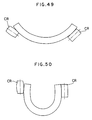
- the roll surface shaped in the form of a concavely curved face serves to form under pressure the strip to be bent. Namely, this roll surface is suitably fitted to the convexly curved face of a forming flower, so that the roll-contacted portion of the strip is not made flat in a stripe-pattern.
- Fig.1 is an illustrative view of the construction of a welded steel pipe manufacturing machine according to the present invention.
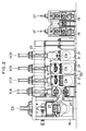
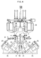
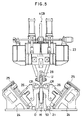
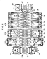
- Fig.2 to Fig.10 show embodiments of the present invention wherein Fig.2 is a side view of the machine in the roll forming process, Fig.3 is a front view of the first center bending roll, Fig.4 is a front view of the third center bending roll, Fig.5 is a front view of the fourth center bending roll, Fig.6 is a plan view of the cage roll, Fig.7 is an enlarged front view of the main part of the first center bending roll, Fig.8 and Fig.9 are enlarged front views of the main parts of the second to fourth center bending rolls, for a small size of a pipe to be produced and for a large size, and Fig. 10 is a graph.
- Fig.32 is a cross sectional view of a portion of the machine shown in Fig.31 wherein the upper roll is incorporated.
- FIG.1 A machine according to the present invention is shown in Fig.1 to Fig.9.
- a side roll SD is arranged between the first and second fin pass rolls, it may be omitted.
- Both the upper and down rolls of the edge bending roll EB are in the form of a split roll and adjustable in width in accordance with the size of pipe to be produced.
- the edge bending roll EB serves to constrain under pressure the strip from its pipe edge-defining portions to the boundaries between the pipe edge-defining portions and its pipe side-defining portions so that the strip is fed, and at the same time, the pipe edge-defining portions and the boundaries are bent almost equally to a finally formed circle whilst anticipating the spring-back.
- the first one-part roll for the range 1 is of caliper-shaped form appropriate to 31.03 mm
- the second for the range 2 is of caliper-shaped form appropriate 43.33 mm
- the third for the range 3 is of caliper-shaped form appropriate to 60.5 mm, respectively.
- each of them is shaped in a caliper-shaped form suitable for the maximum outside diameter of an applicable common range of use.
- the high frequency welder HFW is one kind of resistance welder, whereby a welding current is caused to pass through the resulting seam of the pipe to heat and melt the seam.
- the present invention has the following effects.
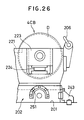
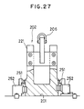
- the first to the fourth center bending rolls 1CB, 2CB, 3CB and 4CB each comprises an upper roll U ⁇ and a down roll D ⁇ which stand opposite to each other, wherein each down roll D ⁇ and each upper roll U ⁇ are mounted on a sub-base plate in the form of a common stand frame 202 for the down rolls, arranged on a base plate 201, and a common stand frame 203 for the upper rolls, respectively.
- the upper roll U and down roll D of the first center bending roll 1CB is each a driving roll connected to a driving means and each of all the other rolls is a non-driven roll.
- the down roll common stand frame 202 is arranged detachably on a base plate 201, and positioned at a predetermined position by a positioning means 204 and a clamping means 205.
- the clamping means 205 is composed so that a semi-circular engaging projection 251 ⁇ is arranged respectively at the front and rear on both sides of the down roll common stand frame 202, and an oil-hydraulic clamp 252 ⁇ is arranged against each of these engaging projections 251 ⁇ and mounted on the base plate 201. Thus, these oil-hydraulic clamps 252 ⁇ will be engaged with each of the engaging projections 251 by oil pressure.
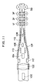
- Each of the upper rolls U ⁇ is journaled on a lifting frame 235 which is lifted by a worm jack 234 ⁇ , and these lifting frames are engaged liftably and slidably on a pair of vertical sliding guides 236, 236 ⁇ , arranged on the horizontal frame 233 .
- the following procedure may be preferably taken for the exchange of rolls in the first to the fourth center bending rolls 1CB, 2CB, 3CB and 4CB.
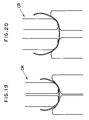
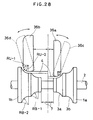
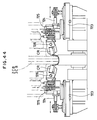
- the convexly curved face portion of the upper roll its cross-sectional profile is shaped in such a way that two sectors having a radius of curvature RU-1 used for forming a thin strip (small in thickness) and a radius of curvature RU-2 used for forming a thick strip (large in thickness) are provided adjacently as shown in Fig.29 and Fig.30.
- the roll surface portion with the radius of curvature RU-1 may be used for strips of minimum thickness to the middle thickness
- the roll surface portion with the radius of curvature RU-2 may be used for strips of the middle thickness to the maximum thickness, respectively.
- a beam 6 is supported as a lift frame which is lifted by a worm jack 42 driven by a press motor 41, and the said beam 6 is pressed by an air cylinder 43 in the same direction as the direction of the forming reaction force.
- slide rails 5 are installed up and down in a direction meeting at right angles with the progressing direction of the strip 4.
- These slide rails are fixed on beam 6 as a lifting frame which is supported at both its right and left ends by the housing 40.
- the said beam 6 is movable up and down with respect to the housing 40 so that the clearance for holding the strip between the said down rolls and the upper rolls, hereinafter mentioned, can be adjusted.
- a pair of right and left main apparatus bodies 10a and 10b are mounted on the slide rails 5. These main apparatus bodies 10a, 10b are mounted for sliding movement on the slide rails 5, and upper roll supporting frames 14 are hung at a given interval from the middle portion of the beam 6 in the longitudinal direction between the slide rails and the beams. Both the right and left ends of the upper roll supporting frame 14 have a threaded portion, and a shaft 13 having a screw-threaded portion engaged with the said threaded portion of the upper roll supporting frame 14 is journaled by the fixing plate portions provided at both the right and left ends between both beams.
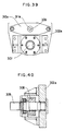
- FIG.32 An assembly of the upper roll 36 and upper roll holder 16a is shown in Fig.32.
- the upper roll in this embodiment is incorporated in the upper roll holder 16a in such a structure as shown in Fig.32, in which the roll change will be carried out by releasing the fastening nuts 38, 39 on the outer face side, drawing out the roll shaft 34, and removing the roll shaft 34 from the upper roll 36.
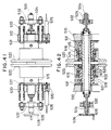
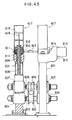
- Fig. 43 shows the upper roll actuating apparatus of the first and second fin pass rolls 1F and 2F, to which the backlash eliminating means is applied.
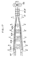
- Fluid-hydraulic cylinders 617, 617 are provided standingly from the said boxes 611, 611, and the lower ends of the piston rods 618, 618 of the said cylinders are connected with the upper ends of the screw shafts, whereby the upper roll 605 can be pulled up by way of the screw shafts 608, 608, with the lift of the pistons 619, 619.
- the pulling-up force of the fluid-hydraulic cylinder is set to be the tare of the pulling-up portions of the said cylinder + the strip forming load x 10 ⁇ 20 %, it is possible to carry out the elimination of backlash with a proper force.
Landscapes
- Engineering & Computer Science (AREA)
- Mechanical Engineering (AREA)
- Bending Of Plates, Rods, And Pipes (AREA)
Claims (15)
- Maschine zum Herstellen eines geschweißten Stahlrohres durch kontinuierliches Bearbeiten eines Streifens mit Walzen, um ihm eine rohrförmige Gestalt zu geben, wobei seine Ränder zur Bildung einer Naht aneinander zur Anlage gebracht werden und die Naht verschweißt wird und wobei die Anordnung eine Serie von Verformungswalzen umfaßt, die sich entlang des sich durch die Anordnung bewegenden Streifens erstrecken, dadurch gekennzeichnet, daß die Anordnung in der Reihenfolge von der Zufuhrseite der Anordnung zur Ausgangsseite der Anordnung eine Randbiegewalze [EB] zum Zusammenpressen des Streifens unter Druck von seinen Randbereichen zu den Grenzen zwischen seinen Randbereichen und seinen die Rohrseiten definierenden Bereichen zum Biegen des Streifens, sowie eine erste Zentralbiegewalze [1CB] zum Zusammenpressen der die Rohrseiten definierenden Bereiche unter Druck zum Biegen der die Rohrseiten definierenden Bereiche, sowie zweite bis vierte Zentralbiegewalzen [2CB, 3CB, 4CB] zum Pressen des Streifens von den Grenzen zwischen den die Rohrseiten definierenden Bereichen und dem den Rohrboden definierenden Bereich zum den Rohrboden definierenden Bereich unter Druck und zum Ausüben von seitlichem Druck auf den Streifen von beiden Seiten, um die Grenzen und den den Rohrboden definierenden Bereich zu biegen, und erste und zweite Finnenpassierwalzen [1F,2F] zum weiteren Verformen des Streifens unter Druck umfaßt und daß die Anordnung überdies zusätzlich mehrere auf beiden Seiten der Zentralbiegewalzen angeordnete Käfigrollen [CR] umfaßt, wobei wenigstens die Randbiegewalze [EB], die erste Zentralbiegewalze [1CB] und die erste und zweite Finnenpassierwalzen [1F, 2F] jeweils eine daran angeordnete Antriebseinrichtung [27] aufweisen, alle oberen Walzen [U] der ersten bis vierten Zentralbiegewalzen [1CB-4CB] in einem Gehäuse [23][233] montiert sind, und alle unteren Walzen [D] der ersten bis vierten Zentralbiegewalzen oder alle unteren Walzen [D] der zweiten bis vierten Zentralbiegewalzen auf einer gemeinsamen Unter-Basis-Platte [50][202] montiert sind.
- Maschine zum Herstellen eines geschweißten Stahlrohres nach Anspruch 1, dadurch gekennzeichnet, daß sowohl die obere Walze [U] wie auch die untere Rolle [D] der Randbiegewalze [EB] und der ersten Zentralbiegewalze [1CB] in der Breite verstellbare geteilte Walzen sind, und daß die untere Walze [D] jeder der zweiten bis vierten Zentralbiegewalzen [2CB-4CB] eine angepaßte, einteilige Walze [16] ist, die für den maximal zu erzeugenden Rohrdurchmesser ausgebildet ist, daß die obere Walze [U] jeder der zweiten und dritten Zentralbiegewalzen [2CB,3CB] eine geteilte, in der Breite verstellbare Walze [17,18] ist, daß die obere Walze [U] der vierten Zentralbiegerolle [4CB] eine einteilige Walze [28] ist und daß die Käfigwalzen [CR] in einer für schräge Vorwärtsbewegung und Zurückbewegung angepaßten Weise montiert sind.
- Maschine zum Herstellen eines geschweißten Stahlrohres nach einem der Ansprüche 1 oder 2, dadurch gekennzeichnet, daß das Gehäuse [23][233] abnehmbar ist, wodurch alle oberen Walzen der ersten bis vierten Zentralbiegewalzen [1CB-4CB] auf einmal durch Austausch besagten Gehäuses [23][233] ersetzt werden können.
- Maschine zur Herstellung eines geschweißten Stahlrohres nach Anspruch 3, dadurch gekennzeichnet, daß das Gehäuse als horizontaler Rahmen [233] ausgebildet ist, der den oberen Teil eines gemeinsamen Standrahmens [203] für die oberen Walzen bildet, der eine Positioniereinrichtung [207] und eine darauf angeordnete Klemmeinrichtung [208] aufweist, wobei die Klemmeinrichtung [208] abnehmbar ist, um den horizontalen Rahmen [233] während des Ersetzens der oberen Rolle zu lösen und daß durch die Positioniereinrichtung [207] ein neuer horizontaler Rahmen an einer vorgegebenen Position positionierbar ist, in welcher er durch die Klemmeinrichtung fixierbar ist.
- Maschine zum Herstellen eines geschweißten Stahlrohres nach einem der vorhergehenden Ansprüche, dadurch gekennzeichnet, daß die gemeinsame Unter-Basis-Platte [50][202] abnehmbar ist, wodurch alle unteren Walzen [D] der ersten bis vierten Zentralbiegewalzen oder alle unteren Rollen [D] der zweiten bis vierten Zentralbiegewalzen auf einmal gemeinsam durch Auswechseln besagter Unter-Basis-Platte [50][202] ausgewechselt werden können.
- Maschine zum Herstellen eines geschweißten Stahlrohres nach Anspruch 5, dadurch gekennzeichnet, daß die gemeinsame Unterbasis in Form eines Standrahmens für die unteren Rollen für die ersten bis vierten Zentralbiegewalzen ausgebildet ist und eine Positionseinrichtung [204] und eine daran angeordnete Klemmeinrichtung [205] vorgesehen ist, wobei die Klemmeinrichtung [205] zum Außereingriffbringen des gemeinsamen Standrahmens während des Ersetzens der unteren Rollen lösbar ist und durch die Positioniereinrichtung [204] ein neuer gemeinsamer Standrahmen an einer vorgegebenen Position positionierbar ist, in welcher er durch die Klemmeinrichtung [205] befestigbar ist.
- Maschine zum Herstellen eines geschweißten Stahlrohres nach einem der vorhergehenden Ansprüche, dadurch gekennzeichnet, daß in den ersten bis vierten Zentralbiegewalzen jede obere Walze [U] an einem gemeinsamen Standrahmen [203] für die oberen Walzen montiert ist und jede untere Walze [D] an einem gemeinsamen Standrahmen [202] für die unteren Walzen montiert ist und die Walzen einzeln bezüglich ihrer jeweiligen Rahmen vertikal justierbar sind.
- Maschine zum Herstellen eines geschweißten Stahlrohres nach einem der vorhergehenden Ansprüche, dadurch gekennzeichnet, daß eine untere Führungsrolle [BGR] zur Aufnahme des Rohres in einem Bereich zwischen der vierten Zentralbiegewalze und der ersten Finnenpassierwalze angeordnet ist.
- Maschine zum Herstellen eines geschweißten Stahlrohres nach einem der vorhergehenden Ansprüche, dadurch gekennzeichnet, daß die Randbiegewalze [EB] eine untere Walze und eine obere Walze umfaßt, die jeweils als geteilte Walzen ausgebildet sind, und deren rechter und linker Teil symmetrisch sind, und daß besagte untere Walze [1a,1b] eine Stufenwalze ist, die mehrere Stufen verschiedenen Außendurchmessers aufweist, wobei die innere Seite den geringeren Durchmesser aufweist, wodurch konkav gekrümmte Teilstücke mit verschiedenen Krümmungsradien [RB-1,RB-2] jeweils in Positionen gegenüber den Rändern des Streifens angeordnet sind, daß besagte obere Walze [36a,36b] ein äußeres Umfangsprofil mit einer derartigen Kontur aufweist, daß nur die äußere Seite der Walze eine konvex gekrümmte Form aufweist, wobei die obere Walze mit ihren Lagerzapfen in einer Halteeinrichtung [16] aufgenommen ist, so daß ihre Position gegen eine jeder Stufe der besagten Stufenwalze gegenüberliegende Position getauscht werden kann und so daß die obere Walze in Richtung der Breite des Streifens geneigt sein kann, wobei die konvex gekrümmte Form der oberen Walze eine Kombination von Sektoren mit verschiedenen Krümmungsradien umfaßt.
- Maschine zur Herstellung eines geschweißten Stahlrohres nach Anspruch 9, dadurch gekennzeichnet, daß das Zentrum der Neigung der oberen Walze der Randbiegewalze sich auf einer Linie befindet, die normal zum Ende der konvex gekrümmten Fläche der oberen Walze ist.
- Maschine zur Herstellung eines geschweißten Stahlrohres nach Anspruch 9 oder 10, dadurch gekennzeichnet, daß die obere Walze der Randbiegewalze eine Stützanordnung aufweist, welche einen Heberahmen [6] aufweist, der anhebbar in einem Gehäuse [40] gelagert ist, sowie einen Tragrahmen [14] für die oberen Rollen, welcher am in Richtung der Breite der oberen Walze beweglichen Heberahmen [6] gelagert ist, wobei die Halterung [16] der oberen Walzen neigbar an dem die oberen Walzen tragenden Rahmen gelagert ist, wobei ein Niederhalter [28] zwischen dem die obere Walze tragenden Rahmen und dem Halter der oberen Walze zum Neigen des Halters der oberen Walze vorgesehen ist, wobei eine Zylinderanordnung [43] zum Drücken des Heberahmens [6] in Richtung der Verformungsreaktionskraft vorgesehen ist, sowie eine Zylinderanordnung [30] zum Anpressen des Halters der oberen Walze in Richtung der Verformungsreaktionskraft.
- Maschine zur Herstellung eines geschweißten Stahlrohres nach einem der vorhergehenden Ansprüche, dadurch gekennzeichnet, daß sie eine Justiereinrichtung für eine der angetriebenen Verformwalzen aufweist, wobei die angetriebene Verformwalze, wie die untere Walze der Randbiegewalze und die obere und unteren Walzen der ersten Zentralbiegewalze linke und rechte geteilte Walzen [305a,305b] aufweisen und die Justiereinrichtung eine hohle Hauptwelle [301] umfaßt, die über Lagerzapfen an ihren Enden gelagert ist; ein Paar linker und rechter Halter [303a,303b] für zylindrische Walzen, die in axialer Richtung auf dem äußeren Umfang des mittleren Teils der besagten hohlen Hauptwelle verschiebbar sind und die die linken und rechten geteilten Walzen jeweils an ihren inneren Enden stützen, sowie Positionsfixiereinrichtungen [304a,304b], die vorgesehen sind, um die Walzenhalter an einer optionalen Position zu halten, ein Getriebe [306] zum mechanischen Ineingriffbringen der hohlen Hauptwelle mit einer Antriebseinheit, welches an einem Ende der Hauptwelle befestigt ist, eine rotierbar montierte Justierwelle [309], die sich durch die hohle Hauptwelle dreht; ein Paar Gewindeelemente [310a,310b] mit unterschiedlichen Gewinderichtungen, die an den Enden der Justierwelle angeordnet sind; Schraubenbewegungseinrichtungen [311a, 311b], die zum Vorwärts- und Rückwärtsbewegen besagter Schraubenelemente mit diesen in Eingriff sind; Übertragungsmechanismen [312a,312b] zum Übertragen der besagten Schraubenvorwärts- und -rückwärtsbewegung, welche zwischen jeder Schraubenbewegungseinrichtung und einem Walzenhalter vorgesehen sind; und ein zum Drehen an besagter Justierwelle vorgesehener Griff [313].
- Maschine zur Herstellung eines geschweißten Stahlrohres nach einem der vorhergehenden Ansprüche, dadurch gekennzeichnet, daß sie eine Justiereinrichtung für eine der nichtangetriebenen Verformwalzen aufweist, wobei die nichtangetriebene Verformwalze, wie jede obere Walze der zweiten bis dritten Zentralbiegewalzen, linke und rechte geteilte Walzen [520] umfaßt und die Justiereinrichtung eine Hauptwelle [501] umfaßt, die dadurch gebildet ist, daß eine äußere Zylinderwelle [503] am äußeren Umfang einer kegelförmigen Welle [502] montiert ist und ihre beiden Enden an tragenden Platten [510] fixiert sind; ein Paar linker und rechter Verschiebehülsen [515] mit einem Positioniermechanismus, die im mittleren Teil der Hauptwelle [501] montiert sind, sodaß sie in axialer Richtung verschiebbar sind und die jeweils linke und rechte geteilte, rotierbar an ihren äußeren Umfängen montierte Walzen aufweisen; Schraubenwellen [504], die bezüglich zueinander in einer entgegengesetzten Schraubrichtung von den Enden besagter Kegelwelle [502] hervorstehen, Nüsse [505], die in besagte Schraubenwellen eingeschraubt sind, Stangen [530], die besagte Verschiebehülsen miteinander verbinden, und eine für die Kegelwelle vorgesehene Rotationseinrichtung [506], die am Ende einer der besagten Schraubenwellen festgelegt ist.
- Maschine zur Herstellung eines geschweißten Stahlrohres nach einem der vorhergehenden Ansprüche, dadurch gekennzeichnet, daß sie für die Randbiegewalze, die Zentralbiegewalzen und die Finnenpassierwalzen eine Einrichtung zur Betätigung der oberen Welle mit einer Einrichtung zur Eliminierung von Spiel aufweist, wobei die Anordnung eine Welle [606] umfaßt, auf welcher die obere Welle [605] montiert ist, sowie Lagerungen [607], die beide Enden der Welle [606] der oberen Walze tragen; eine Schraubenwelle [608], die von jedem der Lager [607] absteht, daß die Schraubenwellen in Niederhaltern [614] mit Schnecken aufgenommen sind, welche an beiden Endteilen einer Schneckenwelle [613] vorgesehen sind, die an einem Ständer [601] gelagert ist, wodurch die obere Walze durch besagte Schraubenwelle [608] durch Drehung besagter Schneckenwelle [613] in sowohl die normale wie auch die gegengesetzte Richtungen nach oben und nach unten bewegt werden kann, und daß die Anordnung auch einen Fluid-Hydraulik-Zylinder [617] umfaßt, der jeweils über den besagten Schraubenwellen [608] angeordnet ist und Kolbenstangen [618] umfaßt, die mit den oberen Enden der Schraubenwellen [608] verbunden sind, wodurch die obere Walze nach oben gezogen werden kann.
- Maschine zur Herstellung eines geschweißten Stahlrohres nach einem der vorhergehenden Ansprüche, dadurch gekennzeichnet, daß die Walzenoberfläche der Käfigrollen mit einer konkav gekrümmten Oberfläche ausgebildet ist, die einen größeren Krümmungsradius als das herzustellende Rohr aufweist.
Applications Claiming Priority (11)
| Application Number | Priority Date | Filing Date | Title |
|---|---|---|---|
| JP1314694A JPH0636943B2 (ja) | 1989-12-04 | 1989-12-04 | 無駆動成形ロールの調整装置 |
| JP314694/89 | 1989-12-04 | ||
| JP1314696A JPH03174922A (ja) | 1989-12-04 | 1989-12-04 | 溶接管のケージロール |
| JP314696/89 | 1989-12-04 | ||
| JP3172/90 | 1989-12-06 | ||
| JP1317290A JPH06104252B2 (ja) | 1989-12-06 | 1989-12-06 | 溶接鋼管の製造装置 |
| JP89317289A JPH03180211A (ja) | 1989-12-06 | 1989-12-06 | 溶接管成形装置 |
| JP3172/89 | 1989-12-06 | ||
| JP306297/90 | 1990-11-14 | ||
| JP2306297A JPH0698402B2 (ja) | 1990-11-14 | 1990-11-14 | 溶接鋼管の帯板縁部成形ロール |
| PCT/JP1990/001572 WO1991008064A1 (en) | 1989-12-04 | 1990-12-04 | Apparatus for manufacturing welded steel pipe and method of operating thereof |
Publications (3)
| Publication Number | Publication Date |
|---|---|
| EP0607430A4 EP0607430A4 (de) | 1992-02-07 |
| EP0607430A1 EP0607430A1 (de) | 1994-07-27 |
| EP0607430B1 true EP0607430B1 (de) | 1996-07-10 |
Family
ID=27551794
Family Applications (1)
| Application Number | Title | Priority Date | Filing Date |
|---|---|---|---|
| EP90917533A Expired - Lifetime EP0607430B1 (de) | 1989-12-04 | 1990-12-04 | Vorrichtung zur herstellung geschweisster stahlrohre |
Country Status (1)
| Country | Link |
|---|---|
| EP (1) | EP0607430B1 (de) |
Cited By (1)
| Publication number | Priority date | Publication date | Assignee | Title |
|---|---|---|---|---|
| CN105499339A (zh) * | 2016-01-13 | 2016-04-20 | 大连三高集团有限公司 | 一种予弯成型装置 |
Families Citing this family (5)
| Publication number | Priority date | Publication date | Assignee | Title |
|---|---|---|---|---|
| US9625067B2 (en) | 2009-09-01 | 2017-04-18 | Sea Ng Corporation | Clamp suitable for increasing the fatigue life of the butt welds of a pipe pressure vessel which is subsequently bent |
| DE102011016173A1 (de) | 2011-04-05 | 2012-10-11 | Bergrohr Gmbh Siegen | Blechbiegemaschine, Verwendung einer solchen zur Herstellung von Schlitzrohren sowie Verfahren zur Formung eines Bleches zu einem Schlitzrohr |
| CN105598194B (zh) * | 2016-03-15 | 2017-08-25 | 丽水市海卓科技有限公司 | 自动拉丝流水线及其工艺 |
| CN106180231B (zh) * | 2016-07-29 | 2019-01-04 | 南通汇丰电子科技有限公司 | 一种拉拔模具及金属线的拉拔系统 |
| CN115635239B (zh) * | 2022-09-07 | 2024-09-06 | 江苏新蓝天钢结构有限公司 | 一种束状钢管异形柱组装和辅助焊接装置及组装焊接方法 |
-
1990
- 1990-12-04 EP EP90917533A patent/EP0607430B1/de not_active Expired - Lifetime
Cited By (1)
| Publication number | Priority date | Publication date | Assignee | Title |
|---|---|---|---|---|
| CN105499339A (zh) * | 2016-01-13 | 2016-04-20 | 大连三高集团有限公司 | 一种予弯成型装置 |
Also Published As
| Publication number | Publication date |
|---|---|
| EP0607430A4 (de) | 1992-02-07 |
| EP0607430A1 (de) | 1994-07-27 |
Similar Documents
| Publication | Publication Date | Title |
|---|---|---|
| US5301869A (en) | Machine for manufacturing welded steel pipes and method for handling the machine | |
| CN111375941B (zh) | 一种纳米薄壁管件自动焊接装置 | |
| EP0565772B1 (de) | Walzgerüst mit drei angetriebenen und einstellbaren Walzen | |
| US4491004A (en) | Apparatus for manufacturing a metal pipe | |
| CN110385355B (zh) | 热轧带钢取样方法及取样线 | |
| JPH04228226A (ja) | 板を筒状に曲げるための成形機及びこの成形機を有する成形設備 | |
| CN115740698B (zh) | 一种桥梁钢结构中的板单元组装焊接系统及焊接方法 | |
| EP0607430B1 (de) | Vorrichtung zur herstellung geschweisster stahlrohre | |
| JP2879609B2 (ja) | ロール成形機 | |
| EP0504495B1 (de) | Rollenrichtmaschine zum Richten von H-Profilen | |
| JP2000334571A (ja) | マッシュ・シーム溶接装置 | |
| US6223575B1 (en) | Tube forming machine using three point bending | |
| CN111468535B (zh) | 一种四轮轧辊机 | |
| CN221017994U (zh) | 一种精密油轧装置 | |
| EP1005921B1 (de) | Schrägwalzwerk | |
| US4505417A (en) | Mill for manufacturing bodies of multilayer high-pressure vessels | |
| US4578977A (en) | Apparatus for performing roll bending on shape metal | |
| JPH06297044A (ja) | フレームベンダー | |
| US3239122A (en) | Apparatus for producing spiral pipe | |
| JP3132401B2 (ja) | 溶接形鋼の溶接部支持装置 | |
| JP3424000B2 (ja) | カラー成形装置 | |
| JP2873336B2 (ja) | 圧延ロールの切削方法および圧延ロール切削装置 | |
| JP3240912B2 (ja) | 金属管の曲げ加工装置およびuチューブの冷間曲げ加工方法 | |
| JP2809333B2 (ja) | 型鋼矯正機 | |
| RU2809059C1 (ru) | Устройство для подгибки кромок листовой заготовки |
Legal Events
| Date | Code | Title | Description |
|---|---|---|---|
| PUAI | Public reference made under article 153(3) epc to a published international application that has entered the european phase |
Free format text: ORIGINAL CODE: 0009012 |
|
| 17P | Request for examination filed |
Effective date: 19910821 |
|
| AK | Designated contracting states |
Kind code of ref document: A1 Designated state(s): DE FR GB |
|
| 17Q | First examination report despatched |
Effective date: 19950102 |
|
| GRAH | Despatch of communication of intention to grant a patent |
Free format text: ORIGINAL CODE: EPIDOS IGRA |
|
| GRAH | Despatch of communication of intention to grant a patent |
Free format text: ORIGINAL CODE: EPIDOS IGRA |
|
| GRAA | (expected) grant |
Free format text: ORIGINAL CODE: 0009210 |
|
| AK | Designated contracting states |
Kind code of ref document: B1 Designated state(s): DE FR GB |
|
| ET | Fr: translation filed | ||
| REF | Corresponds to: |
Ref document number: 69027786 Country of ref document: DE Date of ref document: 19960814 |
|
| PLBE | No opposition filed within time limit |
Free format text: ORIGINAL CODE: 0009261 |
|
| STAA | Information on the status of an ep patent application or granted ep patent |
Free format text: STATUS: NO OPPOSITION FILED WITHIN TIME LIMIT |
|
| 26N | No opposition filed | ||
| REG | Reference to a national code |
Ref country code: GB Ref legal event code: IF02 |
|
| PGFP | Annual fee paid to national office [announced via postgrant information from national office to epo] |
Ref country code: GB Payment date: 20091202 Year of fee payment: 20 Ref country code: FR Payment date: 20091221 Year of fee payment: 20 |
|
| PGFP | Annual fee paid to national office [announced via postgrant information from national office to epo] |
Ref country code: DE Payment date: 20091126 Year of fee payment: 20 |
|
| REG | Reference to a national code |
Ref country code: GB Ref legal event code: PE20 Expiry date: 20101203 |
|
| PG25 | Lapsed in a contracting state [announced via postgrant information from national office to epo] |
Ref country code: GB Free format text: LAPSE BECAUSE OF EXPIRATION OF PROTECTION Effective date: 20101203 |
|
| PG25 | Lapsed in a contracting state [announced via postgrant information from national office to epo] |
Ref country code: DE Free format text: LAPSE BECAUSE OF EXPIRATION OF PROTECTION Effective date: 20101204 |