EP0607430B1 - Appareil de fabrication de tubes en acier soude - Google Patents
Appareil de fabrication de tubes en acier soude Download PDFInfo
- Publication number
- EP0607430B1 EP0607430B1 EP90917533A EP90917533A EP0607430B1 EP 0607430 B1 EP0607430 B1 EP 0607430B1 EP 90917533 A EP90917533 A EP 90917533A EP 90917533 A EP90917533 A EP 90917533A EP 0607430 B1 EP0607430 B1 EP 0607430B1
- Authority
- EP
- European Patent Office
- Prior art keywords
- roll
- rolls
- pipe
- upper roll
- bending
- Prior art date
- Legal status (The legal status is an assumption and is not a legal conclusion. Google has not performed a legal analysis and makes no representation as to the accuracy of the status listed.)
- Expired - Lifetime
Links
Images













Classifications
-
- B—PERFORMING OPERATIONS; TRANSPORTING
- B21—MECHANICAL METAL-WORKING WITHOUT ESSENTIALLY REMOVING MATERIAL; PUNCHING METAL
- B21D—WORKING OR PROCESSING OF SHEET METAL OR METAL TUBES, RODS OR PROFILES WITHOUT ESSENTIALLY REMOVING MATERIAL; PUNCHING METAL
- B21D5/00—Bending sheet metal along straight lines, e.g. to form simple curves
- B21D5/06—Bending sheet metal along straight lines, e.g. to form simple curves by drawing procedure making use of dies or forming-rollers, e.g. making profiles
- B21D5/10—Bending sheet metal along straight lines, e.g. to form simple curves by drawing procedure making use of dies or forming-rollers, e.g. making profiles for making tubes
- B21D5/12—Bending sheet metal along straight lines, e.g. to form simple curves by drawing procedure making use of dies or forming-rollers, e.g. making profiles for making tubes making use of forming-rollers
-
- B—PERFORMING OPERATIONS; TRANSPORTING
- B21—MECHANICAL METAL-WORKING WITHOUT ESSENTIALLY REMOVING MATERIAL; PUNCHING METAL
- B21C—MANUFACTURE OF METAL SHEETS, WIRE, RODS, TUBES, PROFILES OR LIKE SEMI-MANUFACTURED PRODUCTS OTHERWISE THAN BY ROLLING; AUXILIARY OPERATIONS USED IN CONNECTION WITH METAL-WORKING WITHOUT ESSENTIALLY REMOVING MATERIAL
- B21C37/00—Manufacture of metal sheets, rods, wire, tubes, profiles or like semi-manufactured products, not otherwise provided for; Manufacture of tubes of special shape
- B21C37/06—Manufacture of metal sheets, rods, wire, tubes, profiles or like semi-manufactured products, not otherwise provided for; Manufacture of tubes of special shape of tubes or metal hoses; Combined procedures for making tubes, e.g. for making multi-wall tubes
- B21C37/08—Making tubes with welded or soldered seams
Definitions
- a strip edge forming roll for a welded steel pipe serves to pass the strip while it is held between both the upper and down rolls, thereby foraing on the edges of the strip a curved portion corresponding to the size of the pipe to be produced. It is, therefore, necessary to exchange the said rolls, evry time the size of the pipe to be produced is changed. Such roll exchange requires much labor and a number of rolls in proportion to the sizes of the pipes to be produced.
- An upper roll which serves to cause the strip to progress as the strip is held between it and down rolls whereby the strip is gradually shaped into a tubular form, is provided so as to be adjustable in its vertical position, in order that the roll surface of the said upper roll is made to accord with the pass line for strips of different thickness and the strips are pressed down.
- the upper roll actuating apparatus therefor usually comprises screw shafts provided standingly from chocks at both the ends of the upper roll shaft, and these screw shafts are incorporated in worm jucks at both the right and left portions of a worm shaft supported on a stand, whereby the upper roll can be moved up and down, by rotation of the worm shaft in both the normal and reverse directions.
- the elimination of backlash in this appararus is carried out by the use of a special oil-hydraulic jack provided between the chocks at both the ends of a down roll shaft and the chocks of the upper roll shaft.
- each upper roll and the exchange of each down roll may be carried out together with a common stand frame at a stroke.
- the vertical adjustment of each upper roll and each down roll may be carried out individually.
- the down rolls 1a, 1b and upper rolls 36a, 36b are such that space adjustment between the upper and down rolls can be carried out appropriate to the width of the strip 4.
- the down and upper rolls are adjustable in position in the vertical direction.
- the machine has an adjusting device for one of the driven forming rolls wherein the driven forming roll, such as the down roll of the edge bonding roll and the upper and down rolls of the first centre bending roll, comprises left and right split rolls and the adjusting device includes a hollow main shaft journaled at both its ends; a pair of left and right cylindrical roll holders slidably mounted in the axial direction on the outer periphery of the middle portion of said hollow main shaft and holding the left and right split rolls at their inner ends, respectively; position retaining means provided for retaining the roll holders at an optional position; a gear, for mechanically engaging the hollow main shaft to a driving unit, fixed at one end of the main shaft; a rotatably mounted adjustment shaft running through the hollow main shaft; a pair of threaded portions having different thread directions provided at the ends of the adjustment shaft; screw-movers engaged for screw-advance and retreat with said threaded portions; transmission mechanisms for transmitting the said screw-advance and retreat provided between each screw-mover
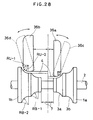
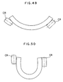
- the roll surface shaped in the form of a concavely curved face serves to form under pressure the strip to be bent. Namely, this roll surface is suitably fitted to the convexly curved face of a forming flower, so that the roll-contacted portion of the strip is not made flat in a stripe-pattern.
- Fig.1 is an illustrative view of the construction of a welded steel pipe manufacturing machine according to the present invention.
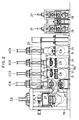
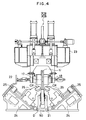
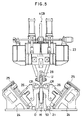
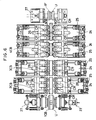
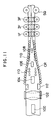
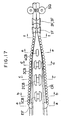
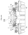
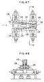
- Fig.2 to Fig.10 show embodiments of the present invention wherein Fig.2 is a side view of the machine in the roll forming process, Fig.3 is a front view of the first center bending roll, Fig.4 is a front view of the third center bending roll, Fig.5 is a front view of the fourth center bending roll, Fig.6 is a plan view of the cage roll, Fig.7 is an enlarged front view of the main part of the first center bending roll, Fig.8 and Fig.9 are enlarged front views of the main parts of the second to fourth center bending rolls, for a small size of a pipe to be produced and for a large size, and Fig. 10 is a graph.
- Fig.32 is a cross sectional view of a portion of the machine shown in Fig.31 wherein the upper roll is incorporated.
- FIG.1 A machine according to the present invention is shown in Fig.1 to Fig.9.
- a side roll SD is arranged between the first and second fin pass rolls, it may be omitted.
- Both the upper and down rolls of the edge bending roll EB are in the form of a split roll and adjustable in width in accordance with the size of pipe to be produced.
- the edge bending roll EB serves to constrain under pressure the strip from its pipe edge-defining portions to the boundaries between the pipe edge-defining portions and its pipe side-defining portions so that the strip is fed, and at the same time, the pipe edge-defining portions and the boundaries are bent almost equally to a finally formed circle whilst anticipating the spring-back.
- the first one-part roll for the range 1 is of caliper-shaped form appropriate to 31.03 mm
- the second for the range 2 is of caliper-shaped form appropriate 43.33 mm
- the third for the range 3 is of caliper-shaped form appropriate to 60.5 mm, respectively.
- each of them is shaped in a caliper-shaped form suitable for the maximum outside diameter of an applicable common range of use.
- the high frequency welder HFW is one kind of resistance welder, whereby a welding current is caused to pass through the resulting seam of the pipe to heat and melt the seam.
- the present invention has the following effects.
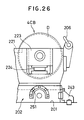
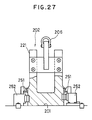
- the first to the fourth center bending rolls 1CB, 2CB, 3CB and 4CB each comprises an upper roll U ⁇ and a down roll D ⁇ which stand opposite to each other, wherein each down roll D ⁇ and each upper roll U ⁇ are mounted on a sub-base plate in the form of a common stand frame 202 for the down rolls, arranged on a base plate 201, and a common stand frame 203 for the upper rolls, respectively.
- the upper roll U and down roll D of the first center bending roll 1CB is each a driving roll connected to a driving means and each of all the other rolls is a non-driven roll.
- the down roll common stand frame 202 is arranged detachably on a base plate 201, and positioned at a predetermined position by a positioning means 204 and a clamping means 205.
- the clamping means 205 is composed so that a semi-circular engaging projection 251 ⁇ is arranged respectively at the front and rear on both sides of the down roll common stand frame 202, and an oil-hydraulic clamp 252 ⁇ is arranged against each of these engaging projections 251 ⁇ and mounted on the base plate 201. Thus, these oil-hydraulic clamps 252 ⁇ will be engaged with each of the engaging projections 251 by oil pressure.
- Each of the upper rolls U ⁇ is journaled on a lifting frame 235 which is lifted by a worm jack 234 ⁇ , and these lifting frames are engaged liftably and slidably on a pair of vertical sliding guides 236, 236 ⁇ , arranged on the horizontal frame 233 .
- the following procedure may be preferably taken for the exchange of rolls in the first to the fourth center bending rolls 1CB, 2CB, 3CB and 4CB.
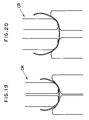
- the convexly curved face portion of the upper roll its cross-sectional profile is shaped in such a way that two sectors having a radius of curvature RU-1 used for forming a thin strip (small in thickness) and a radius of curvature RU-2 used for forming a thick strip (large in thickness) are provided adjacently as shown in Fig.29 and Fig.30.
- the roll surface portion with the radius of curvature RU-1 may be used for strips of minimum thickness to the middle thickness
- the roll surface portion with the radius of curvature RU-2 may be used for strips of the middle thickness to the maximum thickness, respectively.
- a beam 6 is supported as a lift frame which is lifted by a worm jack 42 driven by a press motor 41, and the said beam 6 is pressed by an air cylinder 43 in the same direction as the direction of the forming reaction force.
- slide rails 5 are installed up and down in a direction meeting at right angles with the progressing direction of the strip 4.
- These slide rails are fixed on beam 6 as a lifting frame which is supported at both its right and left ends by the housing 40.
- the said beam 6 is movable up and down with respect to the housing 40 so that the clearance for holding the strip between the said down rolls and the upper rolls, hereinafter mentioned, can be adjusted.
- a pair of right and left main apparatus bodies 10a and 10b are mounted on the slide rails 5. These main apparatus bodies 10a, 10b are mounted for sliding movement on the slide rails 5, and upper roll supporting frames 14 are hung at a given interval from the middle portion of the beam 6 in the longitudinal direction between the slide rails and the beams. Both the right and left ends of the upper roll supporting frame 14 have a threaded portion, and a shaft 13 having a screw-threaded portion engaged with the said threaded portion of the upper roll supporting frame 14 is journaled by the fixing plate portions provided at both the right and left ends between both beams.
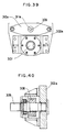
- FIG.32 An assembly of the upper roll 36 and upper roll holder 16a is shown in Fig.32.
- the upper roll in this embodiment is incorporated in the upper roll holder 16a in such a structure as shown in Fig.32, in which the roll change will be carried out by releasing the fastening nuts 38, 39 on the outer face side, drawing out the roll shaft 34, and removing the roll shaft 34 from the upper roll 36.
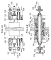
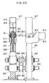
- Fig. 43 shows the upper roll actuating apparatus of the first and second fin pass rolls 1F and 2F, to which the backlash eliminating means is applied.
- Fluid-hydraulic cylinders 617, 617 are provided standingly from the said boxes 611, 611, and the lower ends of the piston rods 618, 618 of the said cylinders are connected with the upper ends of the screw shafts, whereby the upper roll 605 can be pulled up by way of the screw shafts 608, 608, with the lift of the pistons 619, 619.
- the pulling-up force of the fluid-hydraulic cylinder is set to be the tare of the pulling-up portions of the said cylinder + the strip forming load x 10 ⁇ 20 %, it is possible to carry out the elimination of backlash with a proper force.
Landscapes
- Engineering & Computer Science (AREA)
- Mechanical Engineering (AREA)
- Bending Of Plates, Rods, And Pipes (AREA)
Abstract
Claims (15)
- Une machine de fabrication d'un tube soudé en acier en formant par laminage en continu une bande afin qu'elle soit mise en forme de tube avec ses bords aboutés l'un avec l'autre pour former une jonction et en soudant la jonction, dans laquelle l'appareil comprend une séquence de cylindres de formage s'étendant le long de la bande alors qu'elle passe à travers l'appareil, caractérisé en ce que l'appareil comprend, dans l'ordre depuis le côté en amont de l'appareil jusqu'au côté en aval de l'appareil, un cylindre de cintrage de bord (EB) pour contraindre sous pression la bande à partir de ses parties de bord jusqu'aux limites entre ses parties de bord et ses parties de définition latérale de tube pour cintrer la bande, un premier cylindre de cintrage de centre (1CB) pour contraindre sous pression les parties de définition latérale de tube à cintrer les parties de définition latérale de tube, des second à quatrième cylindres de cintrage de centre (2CB, 3CB, 4CB) pour contraindre sous pression la bande à partir des limites entre les parties de définition latérale de tube et la partie de définition de fond de tube jusqu'à la partie de définition de fond de tube et pour appliquer une pression latérale à la bande à partir des deux côtés pour cintrer les limites et la partie de définition de fond de tube, et des premier et second cylindres de passe fine (1F, 2F) pour davantage former la bande sous pression, et comprend en plus une pluralité de cylindres de cage (CR) agencés sur les deux côtés des cylindres de cintrage de centre, dans lequel au moins le cylindre de cintrage de bord (EB), le premier cylindre de cintrage de centre (1CB) et les premier et second cylindres de passe fine (1F, 2F) comportent chacun des moyens d'entraînement (27) prévus sur ces cylindres; tous les cylindres supérieurs (U) du premier au quatrième cylindres de cintrage de centre (1CB à 4CB) sont montés dans une cage (23) (233) et tous les cylindres inférieurs (D) du premier au quatrième cylindres de cintrage de centre ou tous les cylindres inférieurs (D) du second au quatrième cylindres de cintrage de centre sont montés sur une plaque d'embase commune (50) (202).
- Une machine de fabrication d'un tube soudé en acier, selon la revendication 1, dans lequel le cylindre supérieur (U) et le cylindre inférieur (D) du cylindre de cintrage de bord (EB) et du premier cylindre de cintrage de centre (1CB) sont tous deux des cylindres fractionnés réglables en largeur; le cylindre inférieur (D) de chacun des second au quatrième cylindres de cintrage de centre (2CB à 4CB) est un cylindre simple en forme d'étrier (16) approprié au diamètre de tube maximum à fabriquer; le cylindre supérieur (U) de chacun des second et troisième cylindres de cintrage de centre (2CB, 3CB) est un cylindre fractionné (17, 18) réglable en largeur; le cylindre supérieur (U) du quatrième cylindre de cintrage de centre (4CB) est un cylindre simple (28); et les cylindres de cage (CR) sont montés de façon à être réglables pour une avance et un retrait inclinés.
- Une machine de fabrication d'un tube soudé en acier selon la revendication 1 ou 2, dans lequel la cage (23) (233) est amovible de telle manière que tous les cylindres supérieurs des premier au quatrième cylindres de cintrage de centre (1CB à 4CB) puissent être remplacés d'un coup en échangeant ladite cage (23) (233).
- Une machine de fabrication d'un tube soudé en acier selon la revendication 3, dans lequel la cage a la forme d'un cadre horizontal (233) faisant partie d'un bâti de support commun (203) des cylindres supérieurs ayant des moyens de positionnement (207) et des moyens de serrage (208) prévus sur ce cadre, les moyens de serrage (208) étant détachables pour dégager le cadre horizontal (233) pendant le remplacement des cylindres supérieurs et les moyens de positionnement (207) étant susceptibles d'être actionnés pour placer un nouveau cadre horizontal à une position prédéterminée dans laquelle il peut être fixé par les moyens de serrage.
- Une machine de fabrication d'un tube soudé en acier selon l'une quelconque des revendications précédentes, dans lequel la plaque d'embase commune (50) (202) est détachable de telle manière que tous les cylindres inférieurs (D) des premier au quatrième cylindres de cintrage de centre ou tous les cylindres inférieurs (D) des second à quatrième cylindres de cintrage de centre puissent être remplacés d'un coup en échangeant ladite plaque d'embase commune (50) (202).
- Une machine de fabrication d'un tube soudé en acier, selon la revendication 5, dans lequel l'embase commune a la forme d'un bâti de support commun (202) des cylindres inférieurs pour les premier à quatrième cylindres de cintrage de centre et comporte des moyens de positionnement (204) et des moyens de serrage (205) prévus sur ce bâti, les moyens de serrage (205) étant détachables pour dégager le bâti de support commun pendant le remplacement des cylindres inférieurs et les moyens de positionnement (204) étant susceptibles d'être actionnés pour placer un nouveau bâti de support commun à une position prédéterminée dans laquelle il peut être fixé par les moyens de serrage (205).
- Une machine de fabrication d'un tube soudé en acier, selon l'une quelconque des revendications précédentes dans lequel, dans les premier à quatrième cylindres de cintrage de centre, chaque cylindre supérieur (U) est monté sur un bâti de support commun (203) des cylindres supérieurs et chaque cylindre inférieur (D) est monté sur un bâti de support commun (202) des cylindres inférieurs et les cylindres sont réglables verticalement individuellement par rapport à leurs bâtis respectifs.
- Une machine de fabrication d'un tube soudé en acier selon l'une quelconque des revendications précédentes, dans lequel un cylindre de guidage inférieur (BGR) pour recevoir le tube est agencé dans une section entre le quatrième cylindre de cintrage de centre et le premier cylindre de passe fine.
- Une machine de fabrication d'un tube soudé en acier selon l'une quelconque des revendications précédentes, dans lequel le cylindre de cintrage de bord (EB) comprend un cylindre inférieur et un cylindre supérieur, chacun sous la forme de cylindres fractionnés symétriques droit et gauche, dans lequel ledit cylindre inférieur (1a, 1b) est un cylindre à gradins ayant une pluralité de gradins de diamètre extérieur différent, le côté intérieur ayant le plus petit diamètre de telle manière que des parties incurvées de manière concave ayant différents rayons de courbures (RB-1, RB-2) soient prévues respectivement pour être disposées en face des bords de la bande et que ledit cylindre supérieur (36a, 36b) présente un profil périphérique extérieur d'un contour tel que seul le côté extérieur de surface du cylindre ait une forme courbée de manière convexe, dans lequel le cylindre supérieur est tourillonné dans un support (16) afin que sa position puisse être modifiée vers une position opposée à chaque gradin dudit cylindre à gradins et afin que le cylindre supérieur puisse être incliné dans la direction de la largeur de la bande, la forme incurvée de manière convexe du cylindre supérieur comprenant une combinaison de secteurs ayant différents rayons de courbure.
- Une machine de fabrication d'un tube soudé en acier selon la revendication 9, dans lequel le centre d'inclinaison du cylindre supérieur du cylindre de cintrage de bord est fixé sur une ligne normale à l'extrémité de la surface incurvée de manière convexe du cylindre supérieur.
- Une machine de fabrication d'un tube soudé en acier, selon la revendication 9 ou 10, dans lequel le cylindre supérieur du cylindre de cintrage de bord comporte un appareil de support, qui comprend un cadre de levage (6) supporté de manière susceptible d'être soulevée dans une cage (40), un bâti de support (14) de cylindre supérieur supporté sur le cadre de levage (6) de manière mobile dans la direction de la largeur du cylindre supérieur, le support (16) de cylindre supérieur supporté de manière inclinable sur le bâti de support de cylindre supérieur, un appareil de cric (28) prévu entre le bâti de support de cylindre supérieur et le support de cylindre supérieur pour incliner le support de cylindre supérieur, un vérin (43) pour presser le cadre de levage (6) dans la direction de la force de réaction de formage et un vérin (30) pour presser le support de cylindre supérieur dans la direction de la force de réaction de formage.
- Une machine de fabrication d'un tube soudé en acier selon l'une quelconque des revendications précédentes, qui comporte un appareil de réglage pour l'un des cylindres de formage entraîné dans lequel le cylindre de formage entraîné, tel que le cylindre inférieur du cylindre de cintrage de bord et les cylindres inférieur et supérieur du premier cylindre de cintrage de centre, comprend des cylindres fractionnés gauche et droit (305a, 305b) et l'appareil de réglage comprend un arbre creux principal (301) tourillonné à ses deux extrémités; deux supports cylindriques de cylindre gauche et droit (303a, 303b) montés coulissants dans la direction axiale sur la périphérie extérieure de la partie centrale dudit arbre creux principal et maintenant respectivement les cylindres fractionnés gauche et droit à leurs extrémités intérieures; des moyens de retenue en position (304a, 304b) prévus pour retenir les supports de cylindres à une position optionnelle; une roue d'engrenage (306), pour mettre en prise mécaniquement l'arbre creux principal avec une unité motrice, fixée à une extrémité de l'arbre principal; un arbre de réglage (309) monté à rotation et passant à travers l'arbre creux principal ; deux parties filetées (310a, 310b) ayant des sens de filetage différents et prévues aux extrémités de l'arbre de réglage; des organes de déplacement à vis (311a, 311b) vissés pour une avance et un retrait à vis sur lesdites parties filetées ; des mécanismes de transmission (312a, 312b) pour transmettre lesdits avance et retrait à vis prévus entre chaque organe de déplacement à vis et support de cylindre; et une poignée (313) de rotation prévue sur ledit arbre de réglage.
- Une machine de fabrication d'un tube soudé en acier selon l'une quelconque des revendications précédentes, qui comporte un appareil de réglage pour l'un des cylindres de formage non entraînés, dans lequel le cylindre de formage non entraîné, tel que chaque cylindre supérieur des second à troisième cylindres de cintrage de centre, comprend des cylindres fractionnés gauche et droit (520) et l'appareil de réglage comprend un arbre principal (501) formé en montant de manière rotative un arbre extérieur de cylindre (503) sur la périphérie extérieure d'un arbre intérieur (502) et ayant ses extrémités fixées sur des plaques de support (510); deux manchons coulissants gauche et droite (515) ayant un mécanisme de positionnement et montés sur la partie médiane de l'arbre principal (501) afin d'être susceptible de coulisser dans la direction axiale et ayant les cylindres fractionnés gauche et droit montés respectivement à rotation sur leurs périphéries extérieures, des arbres ou tiges fileté(e)s (504) qui sont mutuellement dans une relation de pas inverse, prévus respectivement en saillie à partir des extrémités dudit arbre intérieur (502); des écrous (505) vissée sur les arbres ou tiges fileté(e)s; des barres (530) reliant l'un avec l'autre lesdits manchons coulissants; et des moyens d'entraînement (506) en rotation d'arbre intérieur fixés à l'extrémité de l'un desdits arbres ou tiges fileté(e)s.
- Une machine de fabrication d'un tube soudé en acier selon l'une quelconque des revendications précédentes, qui comprend un appareil d'actionnement de cylindres supérieurs, ayant des moyens de suppression de jeu, pour le cylindre de cintrage de bord, pour les cylindres de cintrage de centre et pour les cylindres de passe fine, la machine comprenant un arbre (606) sur lequel le cylindre supérieur (605) est monté; des amortisseurs (607) supportant les deux extrémités de l'arbre (606) de cylindre supérieur; un arbre fileté (608) partant verticalement de chacun des amortisseurs (607); les arbres filetés étant incorporés dans des crics à vis (614) prévus aux deux parties d'extrémité d'un arbre de vis (613) supporté sur un support (601) de telle manière que le cylindre supérieur puisse être déplacé vers le haut et vers le bas au moyen desdits arbres filetés (608) par la rotation dudit arbre fileté (613) à la fois dans les directions normale et inverse; la machine comprenant également un vérin hydraulique à fluide (617) prévu respectivement au-dessus de chacun desdits arbres filetés (608) et ayant des tiges de piston (618) reliées aux extrémités supérieures des arbres filetés (608) de telle manière que le cylindre supérieur puisse être tiré vers le haut.
- Une machine de fabrication d'un tube soudé en acier selon l'une quelconque des revendications précédentes, dans lequel la surface de cylindre des cylindres de cage a la forme d'une surface incurvée de manière concave présentant un plus grand rayon de courbure que celui du tube à former.
Applications Claiming Priority (11)
| Application Number | Priority Date | Filing Date | Title |
|---|---|---|---|
| JP1314694A JPH0636943B2 (ja) | 1989-12-04 | 1989-12-04 | 無駆動成形ロールの調整装置 |
| JP314694/89 | 1989-12-04 | ||
| JP1314696A JPH03174922A (ja) | 1989-12-04 | 1989-12-04 | 溶接管のケージロール |
| JP314696/89 | 1989-12-04 | ||
| JP3172/90 | 1989-12-06 | ||
| JP1317290A JPH06104252B2 (ja) | 1989-12-06 | 1989-12-06 | 溶接鋼管の製造装置 |
| JP89317289A JPH03180211A (ja) | 1989-12-06 | 1989-12-06 | 溶接管成形装置 |
| JP3172/89 | 1989-12-06 | ||
| JP306297/90 | 1990-11-14 | ||
| JP2306297A JPH0698402B2 (ja) | 1990-11-14 | 1990-11-14 | 溶接鋼管の帯板縁部成形ロール |
| PCT/JP1990/001572 WO1991008064A1 (fr) | 1989-12-04 | 1990-12-04 | Procede et appareil de fabrication de tubes en acier soude |
Publications (3)
| Publication Number | Publication Date |
|---|---|
| EP0607430A4 EP0607430A4 (fr) | 1992-02-07 |
| EP0607430A1 EP0607430A1 (fr) | 1994-07-27 |
| EP0607430B1 true EP0607430B1 (fr) | 1996-07-10 |
Family
ID=27551794
Family Applications (1)
| Application Number | Title | Priority Date | Filing Date |
|---|---|---|---|
| EP90917533A Expired - Lifetime EP0607430B1 (fr) | 1989-12-04 | 1990-12-04 | Appareil de fabrication de tubes en acier soude |
Country Status (1)
| Country | Link |
|---|---|
| EP (1) | EP0607430B1 (fr) |
Cited By (1)
| Publication number | Priority date | Publication date | Assignee | Title |
|---|---|---|---|---|
| CN105499339A (zh) * | 2016-01-13 | 2016-04-20 | 大连三高集团有限公司 | 一种予弯成型装置 |
Families Citing this family (5)
| Publication number | Priority date | Publication date | Assignee | Title |
|---|---|---|---|---|
| US9625067B2 (en) | 2009-09-01 | 2017-04-18 | Sea Ng Corporation | Clamp suitable for increasing the fatigue life of the butt welds of a pipe pressure vessel which is subsequently bent |
| DE102011016173A1 (de) | 2011-04-05 | 2012-10-11 | Bergrohr Gmbh Siegen | Blechbiegemaschine, Verwendung einer solchen zur Herstellung von Schlitzrohren sowie Verfahren zur Formung eines Bleches zu einem Schlitzrohr |
| CN105598194B (zh) * | 2016-03-15 | 2017-08-25 | 丽水市海卓科技有限公司 | 自动拉丝流水线及其工艺 |
| CN106180231B (zh) * | 2016-07-29 | 2019-01-04 | 南通汇丰电子科技有限公司 | 一种拉拔模具及金属线的拉拔系统 |
| CN115635239B (zh) * | 2022-09-07 | 2024-09-06 | 江苏新蓝天钢结构有限公司 | 一种束状钢管异形柱组装和辅助焊接装置及组装焊接方法 |
-
1990
- 1990-12-04 EP EP90917533A patent/EP0607430B1/fr not_active Expired - Lifetime
Cited By (1)
| Publication number | Priority date | Publication date | Assignee | Title |
|---|---|---|---|---|
| CN105499339A (zh) * | 2016-01-13 | 2016-04-20 | 大连三高集团有限公司 | 一种予弯成型装置 |
Also Published As
| Publication number | Publication date |
|---|---|
| EP0607430A4 (fr) | 1992-02-07 |
| EP0607430A1 (fr) | 1994-07-27 |
Similar Documents
| Publication | Publication Date | Title |
|---|---|---|
| US5301869A (en) | Machine for manufacturing welded steel pipes and method for handling the machine | |
| CN111375941B (zh) | 一种纳米薄壁管件自动焊接装置 | |
| EP0565772B1 (fr) | Cage de laminoir à trois cylindres actionnés et ajustables | |
| US4491004A (en) | Apparatus for manufacturing a metal pipe | |
| CN110385355B (zh) | 热轧带钢取样方法及取样线 | |
| JPH04228226A (ja) | 板を筒状に曲げるための成形機及びこの成形機を有する成形設備 | |
| CN115740698B (zh) | 一种桥梁钢结构中的板单元组装焊接系统及焊接方法 | |
| EP0607430B1 (fr) | Appareil de fabrication de tubes en acier soude | |
| JP2879609B2 (ja) | ロール成形機 | |
| EP0504495B1 (fr) | Appareil à rouleaux pour le dressage des profilés en forme de H | |
| JP2000334571A (ja) | マッシュ・シーム溶接装置 | |
| US6223575B1 (en) | Tube forming machine using three point bending | |
| CN111468535B (zh) | 一种四轮轧辊机 | |
| CN221017994U (zh) | 一种精密油轧装置 | |
| EP1005921B1 (fr) | Laminoir à cylindres obliques | |
| US4505417A (en) | Mill for manufacturing bodies of multilayer high-pressure vessels | |
| US4578977A (en) | Apparatus for performing roll bending on shape metal | |
| JPH06297044A (ja) | フレームベンダー | |
| US3239122A (en) | Apparatus for producing spiral pipe | |
| JP3132401B2 (ja) | 溶接形鋼の溶接部支持装置 | |
| JP3424000B2 (ja) | カラー成形装置 | |
| JP2873336B2 (ja) | 圧延ロールの切削方法および圧延ロール切削装置 | |
| JP3240912B2 (ja) | 金属管の曲げ加工装置およびuチューブの冷間曲げ加工方法 | |
| JP2809333B2 (ja) | 型鋼矯正機 | |
| RU2809059C1 (ru) | Устройство для подгибки кромок листовой заготовки |
Legal Events
| Date | Code | Title | Description |
|---|---|---|---|
| PUAI | Public reference made under article 153(3) epc to a published international application that has entered the european phase |
Free format text: ORIGINAL CODE: 0009012 |
|
| 17P | Request for examination filed |
Effective date: 19910821 |
|
| AK | Designated contracting states |
Kind code of ref document: A1 Designated state(s): DE FR GB |
|
| 17Q | First examination report despatched |
Effective date: 19950102 |
|
| GRAH | Despatch of communication of intention to grant a patent |
Free format text: ORIGINAL CODE: EPIDOS IGRA |
|
| GRAH | Despatch of communication of intention to grant a patent |
Free format text: ORIGINAL CODE: EPIDOS IGRA |
|
| GRAA | (expected) grant |
Free format text: ORIGINAL CODE: 0009210 |
|
| AK | Designated contracting states |
Kind code of ref document: B1 Designated state(s): DE FR GB |
|
| ET | Fr: translation filed | ||
| REF | Corresponds to: |
Ref document number: 69027786 Country of ref document: DE Date of ref document: 19960814 |
|
| PLBE | No opposition filed within time limit |
Free format text: ORIGINAL CODE: 0009261 |
|
| STAA | Information on the status of an ep patent application or granted ep patent |
Free format text: STATUS: NO OPPOSITION FILED WITHIN TIME LIMIT |
|
| 26N | No opposition filed | ||
| REG | Reference to a national code |
Ref country code: GB Ref legal event code: IF02 |
|
| PGFP | Annual fee paid to national office [announced via postgrant information from national office to epo] |
Ref country code: GB Payment date: 20091202 Year of fee payment: 20 Ref country code: FR Payment date: 20091221 Year of fee payment: 20 |
|
| PGFP | Annual fee paid to national office [announced via postgrant information from national office to epo] |
Ref country code: DE Payment date: 20091126 Year of fee payment: 20 |
|
| REG | Reference to a national code |
Ref country code: GB Ref legal event code: PE20 Expiry date: 20101203 |
|
| PG25 | Lapsed in a contracting state [announced via postgrant information from national office to epo] |
Ref country code: GB Free format text: LAPSE BECAUSE OF EXPIRATION OF PROTECTION Effective date: 20101203 |
|
| PG25 | Lapsed in a contracting state [announced via postgrant information from national office to epo] |
Ref country code: DE Free format text: LAPSE BECAUSE OF EXPIRATION OF PROTECTION Effective date: 20101204 |