EP0607464A1 - Multifunktionsmesserfassungseinrichtung - Google Patents
Multifunktionsmesserfassungseinrichtung Download PDFInfo
- Publication number
- EP0607464A1 EP0607464A1 EP92402498A EP92402498A EP0607464A1 EP 0607464 A1 EP0607464 A1 EP 0607464A1 EP 92402498 A EP92402498 A EP 92402498A EP 92402498 A EP92402498 A EP 92402498A EP 0607464 A1 EP0607464 A1 EP 0607464A1
- Authority
- EP
- European Patent Office
- Prior art keywords
- sensor
- terminals
- resistor
- processing unit
- connector
- Prior art date
- Legal status (The legal status is an assumption and is not a legal conclusion. Google has not performed a legal analysis and makes no representation as to the accuracy of the status listed.)
- Withdrawn
Links
Images


Classifications
-
- G—PHYSICS
- G01—MEASURING; TESTING
- G01R—MEASURING ELECTRIC VARIABLES; MEASURING MAGNETIC VARIABLES
- G01R15/00—Details of measuring arrangements of the types provided for in groups G01R17/00 - G01R29/00, G01R33/00 - G01R33/26 or G01R35/00
- G01R15/12—Circuits for multi-testers, i.e. multimeters, e.g. for measuring voltage, current, or impedance at will
- G01R15/125—Circuits for multi-testers, i.e. multimeters, e.g. for measuring voltage, current, or impedance at will for digital multimeters
Definitions
- the invention relates to a multifunction measurement acquisition device, characterized in that it comprises a plurality of sensors relating to several different physical quantities, each comprising identification means arranged to provide first identification information, representative of the nature of the physical quantity concerned, and transducer means arranged to provide second information, representative of the value of this physical quantity and supplied in the form of an electrical quantity; and a processing unit arranged to cooperate with any one of said sensors, comprising interpretation means arranged to interpret said first identification information, and processing means arranged to transform said electrical quantity into a single reference electrical quantity based on said first identification information.
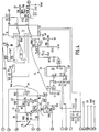
- the measurement acquisition device shown in FIG. 1 comprises a processing unit 20 intended to be electrically connected to one of several sensors such as an inductive current sensor 21 comprising an ammeter clamp, a temperature sensor 22 , a light sensor 23, a humidity sensor 24, a high voltage sensor 25 and a Hall effect intensity sensor comprising an ammeter clamp.
- each sensor is provided with a multi-pin electrical connector not shown in detail, which can be plugged into a multi-pin electrical input connector fitted to the processing unit 20.
- the processing unit is arranged to supply the sensor with which it is equipped at any given time, and in any case processes an electrical signal received from this sensor in the form of a current or a tension.
- Processing consists of delivering, to an output of the processing unit and whatever the electrical signal received from the sensor, an electrical signal of a unique nature, in this case an analog DC voltage.
- An output connector of the processing unit makes it possible to connect the latter to a multimeter 27 known in itself and comprising display means 28 of the electrical signal received and calibration means 29 making it possible to select a scale suitable for the size to display.
- a housing or shoe 30 is mounted in a pluggable manner at a lower end of the processing unit 20. It carries a connector arranged to deliver output signals from the processing unit. It has a first ergonomic function since, by its shape, it promotes the gripping of the processing unit by a user. Its second function may be to provide space to accommodate any accessory of the processing unit. It can in particular be a winder comprising an electric cable with two conductors allowing it to be remotely connected to the multimeter 27. It can also be means of recording data of electronic or computer type, for example means ensuring an interface with an IBM-PC compatible computer.
- the input connector of the processing unit 20 comprises fourteen terminals numbered from 1 to 14 and its output connector comprises two terminals including one terminal 15 supplying said DC voltage and a second terminal constituted by a voltage of reference, these terminals being surrounded by a circle in FIG. 4.
- Terminals 9, 10, 3, 6 respectively deliver reference voltages + U, OV (zero volts), Vref and + 6V to the sensors that need them.
- Terminal 1 is used, except for the humidity sensor, to convey an electrical signal from the sensors and representative of a physical quantity to be measured. It is connected to a double analog multiplexer 31 having two output terminals 13, 3 which can be electronically connected and respectively to two groups of four input terminals 12, 14, 15, 11 and 1, 5, 2, 4, the output terminals 13, 3 being connected simultaneously and respectively to the terminals (12, 1), (14, 5), (15, 2), or (11, 4), depending on the electrical state of two control terminals 9, 10 of the multiplexer 31. Between the terminal 13 of the multiplexer 31 and two reference voltages OV and + U, two diodes D6, D7 are respectively mounted.
- the control terminals 9, 10 of the multiplexer 31 are connected respectively to the terminals 4, 5 of the processing unit.
- a point common to the two resistors is connected to the reference voltage + U while a point common to the two diodes is connected to the reference voltage + 6V via a resistor R23.
- the multiplexer 31 receives a reference voltage + U at a terminal 16 and a reference voltage OV at its terminals 6 to 9. Its two input terminals 12, 1 are directly connected to each other while its input terminals 14, 5 are interconnected by means of a signal processing circuit of an anemometric sensor 32 described in detail below.
- the input terminal 15 of the multiplexer is connected to the input terminal 2 by an amplification circuit 33 comprising an operational amplifier 34 mounted as a follower amplifier.
- a positive input terminal thereof is connected to the input terminal 15 of the multiplexer, to the reference voltage Vref by a resistor R70, and to a movable cursor of a potentiometer P7 by a resistor R69; the potentiometer P7 has two fixed terminals connected respectively to the two reference voltages OV and + 6V.
- An output of the operational amplifier 34 is connected to the reference voltage Vref by two resistors in series R71, R72. A point common to these two resistors is connected to the input terminal 2 of the multiplexer.
- the input terminal 11 of the multiplexer is connected to the reference voltage OV by a resistor R90 while the corresponding input terminal 4 is connected to a circuit 35 for processing the signal from the humidity sensor.
- This processing circuit comprises a monostable flip-flop 36 receiving, at two inputs CX1, CX2 connected to terminals 7 and 8 of the processing unit, a signal from the humidity sensor.
- the input CX1 is connected to the reference voltage + 6V by a resistor R1 and the input CX2 is connected to it by two resistors in parallel R2, R2b.
- the monostable lever 36 is also connected to the reference voltage + 6V by its terminals 3, 5, 11, 13, 16 and to the reference voltage OV by its terminals 1, 15, 8.
- a NAND gate 37 mounted in oscillator has an input connected to a common point of the aforementioned diodes D1, D2, and another input connected on the one hand to the reference voltage OV by a capacitor C1 and on the other hand to an output of the NAND gate by a resistor R24. This output is connected to two inputs Tr1, Tr2 of the monostable flip-flop 36.
- Two outputs Q1, Q'2 of the monostable flip-flop 36 are connected to two inputs of a NAND gate 38, one output of which is connected, via a diode D3, a resistor R25, a potentiometer P5 and a resistor R27 in series, at the inverting input of an operational amplifier 41 mounted as an inverting amplifier.
- a terminal common to the resistor R25 and to the potentiometer P5 is connected to the reference voltage Vref by a capacitor C2.
- a non-inverting input of the amplifier 41 is connected to the reference voltage Vref by a resistor R29 and to a movable cursor of a potentiometer P8 by a resistor R26.
- This potentiometer has two fixed terminals connected respectively to the reference voltages + 6V and OV.
- An output of the amplifier 41 is connected on the one hand to an input terminal 4 of the multiplexer 31, and on the other hand to the inverting input of the amplifier by a resistor R28 connected in series with a thermistor RTH01.
- the humidity sensor usually consists of a non-conductive membrane and electrodes coated with gold which form a capacitor whose value depends on the relative humidity of the ambient air and increases with it.
- This capacitor connected as specified below on the processing unit, varies a width of pulses produced by the monostable rocker 36; the value of the capacitor not being equal to zero when the humidity is zero, we just subtract from the pulses produced at the output of the monostable flip-flop 36 for zero humidity, a slot of width equal to that of these pulses.
- Negative pulses produced by the NAND gate 38 are integrated by the capacitor C2.
- the supply of the monostable scale 36 and the NAND gate 37 by means of the reference voltage + 6V guarantees the stability of these components.
- the NAND gate 37 is inhibited when the humidity sensor is not used.
- a current source 42 comprises an operational amplifier 43 whose inverting input is connected on the one hand to the reference voltage OV by a resistor R18, and on the other hand to an output of the amplifier by a resistor R14. Its non-inverting input is connected on the one hand to the reference voltage Vref, on the other hand to the output of the amplifier by two resistors in series R16, R15. A point common to these two resistors is connected to the input terminal 13 of the processing unit.
- This current source 42 is intended to supply the Hall effect intensity sensor.
- the Hall effect intensity sensor delivers a voltage proportional to the current to be measured, which is itself measured by means of a differential amplifier 44.
- This comprises two operational amplifiers 45, 46 connected respectively to two input terminals 14, 12 of the processing unit by two resistors R5, R6, from their non-inverting input. Their inverting inputs are interconnected by a resistor R7 and a potentiometer R3 connected in series and connected to an output of the amplifier by a resistor R8, R9.
- the inverting input of amplifier 45 is connected by a resistor R12, on the one hand to the reference voltage Vref by a resistor R3, on the other hand to a movable cursor of a potentiometer P4. This has two fixed terminals connected respectively to the two reference voltages OV and + 6V.
- a third operational amplifier 47 has an inverting input and a non-inverting input respectively connected to the outputs of amplifiers 45, 46 by two resistors R10, R11. Its inverting input is connected, as well as an amplifier output, to the input terminal 2 of the processing unit, while its non-inverting input is connected to the voltage source Vref by a resistor R4. A voltage present at this input terminal 2 is transmitted to the input terminal 1 of the processing unit by means of a potentiometer located in the Hall effect intensity sensor.
- An operational amplifier 50 mounted as a non-inverting amplifier has a non-inverting input connected, on the one hand by a resistor R73 to the output terminal 3 of the multiplexer, and on the other hand to a movable cursor of a potentiometer P1 by two resistors R74, R76 connected in series. A point common to these two resistors is connected to the reference voltage Vref by a resistor R75. Two fixed terminals of potentiometer P1 are connected to the two reference voltages OV, + 6V.
- An inverting input of the amplifier 50 is connected to an output thereof by two resistors R77, R78 connected in series.
- the output terminal 15 of the processing unit is connected, on the one hand to a point common to the two resistors R77, R78 by a resistor R79, on the other hand to the reference voltage Vref by a capacitor C10.
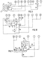
- FIG. 5 is shown the signal processing circuit from the anemometric sensor, that is to say the sensor capable of indicating the speed of flow of a fluid such as air.
- This signal is not directly proportional to this speed, it is processed by a logarithmic amplifier carrying out a mathematical rise to a power.
- This amplifier includes an operational amplifier 51 and two NPN transistors 52 and 53.
- An inverting input of the operational amplifier 51 is connected by a resistor R50 to the terminal 14 of the multiplexer 31, this same terminal being connected to the reference voltage Vref by a resistor R49.
- This inverting input is also connected, on the one hand to an output of the amplifier 51 by means of a capacitor C8, on the other hand to the collector of the transistor 52 whose base is connected to the reference voltage Vref and whose l the transmitter is connected to the output of the amplifier 51 via a resistor R52.
- a non-inverting input of the amplifier 51 is connected to the reference voltage Vref via a resistor R51.
- To the emitter of transistor 52 are connected on the one hand the reference voltage Vref by means of a diode D8, on the other hand the emitter of transistor 53 whose base and collector are connected to the voltage of reference + 6V by a common resistor R53.
- An operational amplifier 54 introduces a gain which fixes the elevation to the power produced by the preceding logarithmic amplifier. It has a non-inverting input connected to the collector of transistor 53 and an inverting input connected to the reference voltage Vref by a resistor R55. An output of the amplifier 54 is connected to the emitter of an NPN transistor 55 by a resistor R57. The base and the collector of this latter transistor are interconnected and connected, on the one hand to the reference voltage + 6V by a resistor 56 and on the other hand to the inverting input of the operational amplifier 54 by a resistor R54. Finally, the emitter of transistor 55 is connected to the reference voltage Vref by a diode D9.
- the circuit of FIG. 5 comprises a last operational amplifier 57.
- An inverting input of this amplifier is connected to the collector of a last NPN transistor 56 whose base is connected to the reference voltage Vref and whose emitter is connected to the emitter of the preceding transistor 55.
- This inverting input is also connected to the output of the amplifier 57 on the one hand by a capacitor C9, on the other hand by a resistor 58 connected in series with a potentiometer P6, these two elements being arranged in parallel on the capacitor C9 .
- a non-inverting input of the amplifier 57 is connected, by two resistors R59 and R61 connected in series, to the reference voltage Vref.
- a point common to the two above-mentioned resistors is connected via a resistor R62 at the reference voltage + 6V, and by a resistor R60 at the reference voltage 0V. Finally, the output of this amplifier is connected to terminal 5 of the multiplexer 31.
- This electronic circuit performs several functions. In the event that the sensor used requires a supply of electricity, this circuit makes an appropriate connection with voltage or current sources provided in the processing unit. This electronic circuit also makes it possible to compensate for the dispersion of the nominal values of the sensors so as to make them interchangeable with respect to the processing unit. Finally, it makes it possible to control the multiplexer 31 of the processing unit at a position corresponding to the type of sensor concerned.
- Figure 6 shows the electronic circuit of the inductive current sensor.
- a current passing through a rectilinear conductor 60 being to be measured, a magnetic circuit 61 makes it possible to guide an electric field produced by the current.
- An induced current in a coil 62 disposed around the magnetic circuit 61 is converted into an electrical voltage by means of a resistor R1 disposed at the terminals of the coil 62.
- the output connector of each sensor is arranged to cooperate with the connector of Entrance of the processing unit. Its terminals effectively connected to the electronic circuit of the sensor bear a number identical to the terminal of the connector of the processing unit with which they must cooperate.
- the terminals of the coil 62 are connected to the terminals 1 and 3 of the connector.
- the terminals 4, 5 and 10 are interconnected, which has the effect of bringing the control terminals 9, 10 of the multiplexer 31 to potential 0, and of connecting the output terminals 13, 3 of the multiplexer with the terminals of entry 12 and 1 of it respectively.
- FIG. 7 is an electronic circuit of a high voltage sensor capable of taking a high voltage present between two terminals 63 and 64.
- a voltage divider constituted by two resistors R1 and R2 makes it possible to bring to terminals 1 and 3 of the connector a reduced value voltage.
- the terminals 4, 5 and 10 are connected in the same way as in the case of FIG. 6, so that the multiplexer 31 is in the same electronic state.
- the electronic circuit of the humidity sensor represented in FIG. 8 comprises a loop constituted by several electronic components arranged in series, namely a capacitor C1, a humidifier 70 itself forming a capacitor, a capacitor C2, a resistor R1, a potentiometer P2 mounted between two fixed terminals, and a resistor R2.
- a common point between the resistor R1 and the capacitor C2 is connected to the terminal 7 of the connector of the sensor, while a movable cursor of the potentiometer P2 is connected to a terminal 6 of the connector by a potentiometer P1.
- the terminal 10 of the connector is connected on the one hand to this cursor by a capacitor C4, and on the other hand to a common point between the capacitor C1 and the humidity 70.
- the terminal 8 of the connector is connected to a common point between resistor R2 and capacitor C1. Furthermore, the terminals 4 and 5 of the connector are not connected, which has the effect of placing the multiplexer 31 in the state shown in FIG. 4, in which its output terminals 13 and 3 are connected to its terminals entry 11 and 4 respectively.
- an electrical conductor 71 traversed by a current to be measured generates a magnetic field in which a magnetic circuit 72 is bathed. If one places in an air gap of the magnetic circuit 72 a wafer made of a particular material such as germanium or selenium, this wafer being traversed by a current I, the action of the magnetic field which crosses the wafer causes between two ends of the latter to appear a voltage U representative of the current at measure.
- Current I injected into the sensor through terminal 13 of its connector, returns to the processing unit through terminal 3.
- Voltage U is recovered at terminals 14 and 12 of the sensor connector.
- the terminals 4, 5 and 10 of the sensor connector are interconnected, which has the effect of placing the multiplexer 31 in a position in which its output terminals 13, 3 are connected respectively to its input terminals 15, 2 the terminals 1 and 2 of the sensor connector are linked together by a potentiometer P1, and the terminal 1 is connected to terminal 3 by a resistor R1.
- the electronic circuit of the light sensor shown in FIG. 10 comprises a photodiode 73 including a filter centered on a wavelength of 550 microns, therefore on visible light, and has a response identical to that of the human eye.
- This photodiode 73 is connected between the input terminals 3 of an operational amplifier 74 which performs a current / voltage conversion.
- a capacitor C1 and a resistor R1 are each mounted between the inverting input 2 of the amplifier and an output 6.
- the non-inverting input 3 of the amplifier is connected to its output 6 by a resistor R4 connected in series with a potentiometer P2 by fixed terminals thereof.
- a movable cursor of the potentiometer P2 is connected to a terminal 1 of the connector of the sensor.
- the terminals 12 and 14 of the sensor are each connected by a resistor R2, respectively R3, to the output 6 of the amplifier 74.
- a terminal 11 of the sensor is connected to the inverting input 2 of the amplifier 74.
- the terminal 11 leads to a switch 75 placed in the processing unit (FIG. 4) allowing the signal level to be calibrated by multiplication by factors equal to 10 LUX, 100 LUX and 1000 LUX.
- a power supply terminal 7 of the amplifier 74 is connected to the terminal 9 of the sensor connector, while a power supply terminal 4 of this same amplifier is connected to the terminal 10 of the sensor connector.
- Two other power supply terminals of the amplifier 74 designated by 1 and 5 are connected together by a potentiometer P1 mounted between its fixed terminals, while a movable cursor of this potentiometer is connected to a terminal 6 of the connector of the sensor.
- the terminals 4 and 5 of the sensor connector are connected to terminal 10, which has the effect of placing the multiplexer 31 in a position in which its output terminals 13, 3 are respectively connected to its input terminals 14, 5 .
- the electronic circuit of the temperature sensor represented in FIG. 11, includes an operational amplifier 80, an inverting input 2 of which is connected to a terminal 10 of the sensor connector by a resistor R1 and a potentiometer P1, while a non-input reverser 3 of this amplifier is connected, by a resistor R2 and a potentiometer P2, to this same terminal 10.
- a resistor R4 in series with an assembly comprising three components in parallel, namely a temperature probe 81 bearing the commercial reference PT 100, and two diodes D1, D2 mounted head to tail.
- a common point between the resistor R4 and said assembly is connected to a terminal 3 of the connector of the sensor by a resistor R5.
- the non-inverting input 3 of the amplifier 80 is connected to this same terminal 3 of the connector of the sensor by a resistor R3.
- the output 6 of the amplifier 80 is directly connected to a terminal 1 of the connector of the sensor.
- Power supply inputs of amplifier 80, respectively referenced 4 and 7, are connected on the one hand to terminal 10 and on the other hand to terminal 9 of the sensor connector.
- Terminal 5 of the sensor connector is connected to its terminal 10 while its terminal 4 is in the air, which has the effect of placing the multiplier 31 in a position in which its output terminals 13, 3 are connected with its input terminals 15, 2.
- the temperature probe 81 is crossed by a constant current. A resistance / voltage conversion is therefore obtained at the output of the amplifier 80.
- the components P2, R2, R3 allow an offset at the origin so as to compensate for the resistance of the probe at 0 ° C.
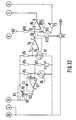
- the electronic circuit of an anemometric sensor is shown in Figure 12.
- the circuit includes a resistive assembly consisting of three branches arranged in parallel.
- a first branch comprises a resistor R4 connected in series with a thermistor 90.
- a second branch comprises two resistors R5 and R7 in series and a potentiometer P1.
- a third branch comprises a resistor R6 in series with a silicon probe 91.
- This resistive assembly is connected between a terminal 10 of the connector of the sensor and the collector of a PNP transistor 92.
- a common point between the resistor R4 and the thermistor 90 is connected to an inverting input of an operational amplifier 93 whose non-inverting input is connected to a common point between the resistors R5 and R7.
- a capacitor C1 is mounted between the inverting input of amplifier 85 and its output. This output is connected to the base of transistor 92 by a resistor R2.
- the base of transistor 92 is connected to terminal 9 of the sensor connector by a resistor R1 while its emitter is connected directly to this terminal and its collector is connected to it by a resistor R3.
- a common point between the resistor R6 and the silicon probe 91 is connected to the non-inverting input of a second operational amplifier 94 mounted as a follower amplifier. An output of this second amplifier 94 is connected to the non-inverting input of a third operational amplifier 95 by means of a resistor R8. Amplifier 95 is mounted as a non-inverting amplifier. Its inverting input is connected to its output by a resistor R10 and it is also connected to a terminal 3 of the sensor connector by a resistor R11 in series with a potentiometer P2.
- a non-inverting input of the amplifier 95 is connected to the reference voltage + 6V by means of a resistor P9 and to a movable cursor of a potentiometer P3 by a resistor R12. Fixed terminals of potentiometer P3 are respectively connected to the reference voltage + 6V and to terminal 10 of the sensor connector. A terminal 4 of the sensor connector is connected to its terminal 10 while its terminal 5 is in the air. Thus the multiplexer 31 is in a state according to which its outputs 13, 3 are connected with its inputs 14, 5.
- the amplifier 93 and the components associated with it maintain balance in the bridge R4, thermistor 90, R5, R7 and therefore keep the resistance of the thermistor 90 constant. Given its nature, its temperature is therefore constant.
- the voltage is sent to amplifier 94 for adjustment to 0 and end of scale. Since the voltage variation is not proportional to the speed of the air, the signal is routed in the processing unit to the circuit 32, raising the power.
- the processing unit therefore defines an electronic circuit capable, from a signal emitted by any one of several sensors, of delivering a direct voltage proportional to the value of the measured quantity: - inductive current sensor 1 mV / A - Hall effect intensity sensor 1 mV / A - humidity sensor 1 mV /% RH - temperature sensor 1 mV / ° C - light sensor 1 mV / lx with factor 10, 100 or 1000 - high voltage sensor 100 mV / KV - anemometric sensor 10 mV / ms.
- the processing unit is mounted on an electronic card 100 in a box 101.
- This box includes a supply battery 102 of type 6LR61 of 9V, a control button 103 intended to control the opening the current clamp of certain sensors.
- the housing 101 carries, on a side face opposite to a side face receiving the control button 103, a zero adjustment button 104, an electroluminescent dioae 105 for controlling power-up and for checking the state of the battery, an on / off switch 106, and the light measurement range switch 75.
Landscapes
- Physics & Mathematics (AREA)
- General Physics & Mathematics (AREA)
- Indication And Recording Devices For Special Purposes And Tariff Metering Devices (AREA)
Priority Applications (1)
| Application Number | Priority Date | Filing Date | Title |
|---|---|---|---|
| EP92402498A EP0607464A1 (de) | 1992-09-11 | 1992-09-11 | Multifunktionsmesserfassungseinrichtung |
Applications Claiming Priority (1)
| Application Number | Priority Date | Filing Date | Title |
|---|---|---|---|
| EP92402498A EP0607464A1 (de) | 1992-09-11 | 1992-09-11 | Multifunktionsmesserfassungseinrichtung |
Publications (1)
| Publication Number | Publication Date |
|---|---|
| EP0607464A1 true EP0607464A1 (de) | 1994-07-27 |
Family
ID=8211705
Family Applications (1)
| Application Number | Title | Priority Date | Filing Date |
|---|---|---|---|
| EP92402498A Withdrawn EP0607464A1 (de) | 1992-09-11 | 1992-09-11 | Multifunktionsmesserfassungseinrichtung |
Country Status (1)
| Country | Link |
|---|---|
| EP (1) | EP0607464A1 (de) |
Cited By (3)
| Publication number | Priority date | Publication date | Assignee | Title |
|---|---|---|---|---|
| KR100349882B1 (ko) * | 2000-07-24 | 2002-08-24 | 주식회사 웬스정밀 | 다기능 계측 장치 |
| KR100667887B1 (ko) | 2005-03-28 | 2007-01-15 | 주식회사 웬스정밀 | 운영 시스템기반 멀티스코프 |
| CN110646028A (zh) * | 2019-10-30 | 2020-01-03 | 上海绿页科技发展有限公司 | 万能传感器及微电脑数显传感控制器系统 |
Citations (4)
| Publication number | Priority date | Publication date | Assignee | Title |
|---|---|---|---|---|
| US3943440A (en) * | 1974-10-03 | 1976-03-09 | Hewlett-Packard Company | Sensitivity coding circuit for an electronic instrument |
| EP0114536A1 (de) * | 1982-12-03 | 1984-08-01 | Solomat France S.A. | Vielfachsondenmessgerät |
| EP0212045A2 (de) * | 1985-07-11 | 1987-03-04 | Raimund Wilhelm | Anpassung eines Anzeige- oder Auswertgerätes an einen Sensor |
| EP0373982A1 (de) * | 1988-11-14 | 1990-06-20 | Itt Composants Et Instruments | Messgerät für verschiedene elektrische Grössen |
-
1992
- 1992-09-11 EP EP92402498A patent/EP0607464A1/de not_active Withdrawn
Patent Citations (4)
| Publication number | Priority date | Publication date | Assignee | Title |
|---|---|---|---|---|
| US3943440A (en) * | 1974-10-03 | 1976-03-09 | Hewlett-Packard Company | Sensitivity coding circuit for an electronic instrument |
| EP0114536A1 (de) * | 1982-12-03 | 1984-08-01 | Solomat France S.A. | Vielfachsondenmessgerät |
| EP0212045A2 (de) * | 1985-07-11 | 1987-03-04 | Raimund Wilhelm | Anpassung eines Anzeige- oder Auswertgerätes an einen Sensor |
| EP0373982A1 (de) * | 1988-11-14 | 1990-06-20 | Itt Composants Et Instruments | Messgerät für verschiedene elektrische Grössen |
Non-Patent Citations (2)
| Title |
|---|
| ELECTRONIQUE RADIO PLANS no. 505, Décembre 1989, PARIS FR pages 17 - 19 'Le système COMPA et le COMPAMATIC 2 de Chauvin Arnoux' * |
| ELECTRONIQUE RADIO PLANS no. 512, Juillet 1990, PARIS FR pages 19 - 21 'Le Normameter MP 14' * |
Cited By (3)
| Publication number | Priority date | Publication date | Assignee | Title |
|---|---|---|---|---|
| KR100349882B1 (ko) * | 2000-07-24 | 2002-08-24 | 주식회사 웬스정밀 | 다기능 계측 장치 |
| KR100667887B1 (ko) | 2005-03-28 | 2007-01-15 | 주식회사 웬스정밀 | 운영 시스템기반 멀티스코프 |
| CN110646028A (zh) * | 2019-10-30 | 2020-01-03 | 上海绿页科技发展有限公司 | 万能传感器及微电脑数显传感控制器系统 |
Similar Documents
| Publication | Publication Date | Title |
|---|---|---|
| FR2671518A1 (fr) | Systeme de mesure de pression et de temperature de pneumatique. | |
| EP0019540B1 (de) | Vorrichtung zum Messen einer Flüssigkeitshöhe | |
| CA2187486C (fr) | Amplificateur de charge differentiel pour capteur piezoelectrique | |
| FR2640373A1 (fr) | Chaines de mesure dimensionnelle capacitive a sortie lineaire | |
| EP0256071B1 (de) | Temperaturregelungseinrichtung eines gehäuses | |
| FR2656427A1 (fr) | Circuit de mesure du niveau d'un signal electrique comprenant des moyens de correction de decalage et application aux amplificateurs a commande automatique de gain. | |
| EP0607464A1 (de) | Multifunktionsmesserfassungseinrichtung | |
| FR2580070A1 (de) | ||
| EP1671140B1 (de) | Vorrichtung zur messung eines magnetfeldes | |
| EP2877824B1 (de) | Selbstkalibrierender kalorimeter mithilfe von elektrischer substitution | |
| FR2673715A1 (fr) | Dispositif d'acquisition de mesures multifonction. | |
| FR2574932A1 (fr) | Appareil de mesure des caracteristiques debit-pression d'un gaz traversant un echantillon de produit a deux faces | |
| EP0662264B1 (de) | Verfahren und vorrichtung zur reglung des strommittelwertes in einer durch veränderbares tastverhältnis gesteuerten induktiven last | |
| FR2524981A1 (fr) | Balance electronique a haute resolution | |
| FR2793023A1 (fr) | Dispositif d'identification automatique de capteur utilise sur banc d'essais, et banc d'essais equipe de tels dispositifs | |
| EP2492643A1 (de) | Detektor und Konfigurationsvorrichtung des Detektors | |
| EP0511078B1 (de) | Vorrichtung zur Steuerung eines Kreuzspuleninstrumentes | |
| EP0169288B1 (de) | Temperaturkompensationseinrichtung für einen Sensor und Einstellverfahren | |
| EP1336082B1 (de) | Kapazitiver messwertgeber | |
| US6590690B2 (en) | Electronically modulating an optical light source | |
| FR2552874A1 (fr) | Tete de mesure monovoie et installation de telemesure en comportant application | |
| EP0475832B1 (de) | Elektronische Messschaltung mit einer gesteuerten elektrischen Versorgung für eine Widerstandssonde | |
| EP0300394B1 (de) | Einrichtung zur Erfassung und Verarbeitung von Daten | |
| FR2536553A1 (fr) | Dispositif de regulation du type pid delivrant une tension de sortie de polarite donnee | |
| FR2794863A1 (fr) | MONTAGE ELECTRIQUE D'UN CAPTEUR DE MESURE DES NOx ET SON PROCEDE D'UTILISATION |
Legal Events
| Date | Code | Title | Description |
|---|---|---|---|
| PUAI | Public reference made under article 153(3) epc to a published international application that has entered the european phase |
Free format text: ORIGINAL CODE: 0009012 |
|
| AK | Designated contracting states |
Kind code of ref document: A1 Designated state(s): DE GB IT |
|
| 17P | Request for examination filed |
Effective date: 19950118 |
|
| 17Q | First examination report despatched |
Effective date: 19960814 |
|
| STAA | Information on the status of an ep patent application or granted ep patent |
Free format text: STATUS: THE APPLICATION IS DEEMED TO BE WITHDRAWN |
|
| 18D | Application deemed to be withdrawn |
Effective date: 19961228 |