EP0607577A2 - Arrangement et méthode pour installer des bandes à vide dans des margeurs - Google Patents
Arrangement et méthode pour installer des bandes à vide dans des margeurs Download PDFInfo
- Publication number
- EP0607577A2 EP0607577A2 EP93120242A EP93120242A EP0607577A2 EP 0607577 A2 EP0607577 A2 EP 0607577A2 EP 93120242 A EP93120242 A EP 93120242A EP 93120242 A EP93120242 A EP 93120242A EP 0607577 A2 EP0607577 A2 EP 0607577A2
- Authority
- EP
- European Patent Office
- Prior art keywords
- suction
- machine
- frame
- sheet
- belt
- Prior art date
- Legal status (The legal status is an assumption and is not a legal conclusion. Google has not performed a legal analysis and makes no representation as to the accuracy of the status listed.)
- Granted
Links
- 238000000034 method Methods 0.000 title claims description 10
- 238000007639 printing Methods 0.000 claims description 45
- 238000007789 sealing Methods 0.000 claims description 16
- 230000008878 coupling Effects 0.000 claims description 4
- 238000010168 coupling process Methods 0.000 claims description 4
- 238000005859 coupling reaction Methods 0.000 claims description 4
- 230000008569 process Effects 0.000 claims description 3
- 239000004744 fabric Substances 0.000 claims 1
- 238000012545 processing Methods 0.000 abstract description 6
- 238000013461 design Methods 0.000 description 10
- 210000000078 claw Anatomy 0.000 description 5
- 239000000463 material Substances 0.000 description 4
- 230000008859 change Effects 0.000 description 3
- 238000003780 insertion Methods 0.000 description 3
- 230000037431 insertion Effects 0.000 description 3
- 238000012423 maintenance Methods 0.000 description 3
- 238000004026 adhesive bonding Methods 0.000 description 2
- 230000015572 biosynthetic process Effects 0.000 description 2
- 238000007645 offset printing Methods 0.000 description 2
- 238000012549 training Methods 0.000 description 2
- 238000003466 welding Methods 0.000 description 2
- 238000006243 chemical reaction Methods 0.000 description 1
- 239000003292 glue Substances 0.000 description 1
- 238000009434 installation Methods 0.000 description 1
- 238000003032 molecular docking Methods 0.000 description 1
- 239000004810 polytetrafluoroethylene Substances 0.000 description 1
- 229920001343 polytetrafluoroethylene Polymers 0.000 description 1
- 239000004576 sand Substances 0.000 description 1
- 230000008719 thickening Effects 0.000 description 1
Images


Classifications
-
- B—PERFORMING OPERATIONS; TRANSPORTING
- B65—CONVEYING; PACKING; STORING; HANDLING THIN OR FILAMENTARY MATERIAL
- B65H—HANDLING THIN OR FILAMENTARY MATERIAL, e.g. SHEETS, WEBS, CABLES
- B65H11/00—Feed tables
- B65H11/002—Feed tables incorporating transport belts
- B65H11/005—Suction belts
-
- B—PERFORMING OPERATIONS; TRANSPORTING
- B65—CONVEYING; PACKING; STORING; HANDLING THIN OR FILAMENTARY MATERIAL
- B65H—HANDLING THIN OR FILAMENTARY MATERIAL, e.g. SHEETS, WEBS, CABLES
- B65H2402/00—Constructional details of the handling apparatus
- B65H2402/10—Modular constructions, e.g. using preformed elements or profiles
-
- B—PERFORMING OPERATIONS; TRANSPORTING
- B65—CONVEYING; PACKING; STORING; HANDLING THIN OR FILAMENTARY MATERIAL
- B65H—HANDLING THIN OR FILAMENTARY MATERIAL, e.g. SHEETS, WEBS, CABLES
- B65H2402/00—Constructional details of the handling apparatus
- B65H2402/60—Coupling, adapter or locking means
-
- B—PERFORMING OPERATIONS; TRANSPORTING
- B65—CONVEYING; PACKING; STORING; HANDLING THIN OR FILAMENTARY MATERIAL
- B65H—HANDLING THIN OR FILAMENTARY MATERIAL, e.g. SHEETS, WEBS, CABLES
- B65H2406/00—Means using fluid
- B65H2406/30—Suction means
- B65H2406/32—Suction belts
- B65H2406/321—Suction belts integral in feed table
-
- B—PERFORMING OPERATIONS; TRANSPORTING
- B65—CONVEYING; PACKING; STORING; HANDLING THIN OR FILAMENTARY MATERIAL
- B65H—HANDLING THIN OR FILAMENTARY MATERIAL, e.g. SHEETS, WEBS, CABLES
- B65H2406/00—Means using fluid
- B65H2406/30—Suction means
- B65H2406/32—Suction belts
- B65H2406/322—Suction distributing means
- B65H2406/3223—Suction distributing means details of the openings in the belt, e.g. shape, distribution
-
- B—PERFORMING OPERATIONS; TRANSPORTING
- B65—CONVEYING; PACKING; STORING; HANDLING THIN OR FILAMENTARY MATERIAL
- B65H—HANDLING THIN OR FILAMENTARY MATERIAL, e.g. SHEETS, WEBS, CABLES
- B65H2601/00—Problem to be solved or advantage achieved
- B65H2601/30—Facilitating or easing
- B65H2601/32—Facilitating or easing entities relating to handling machine
- B65H2601/324—Removability or inter-changeability of machine parts, e.g. for maintenance
Definitions
- the invention relates to a feed table of a sheet-fed printing machine with conveyor belts for conveying paper sheets from the lay-up stack over an area for lateral alignment to subsequent printing units, and to a method for fastening suction belts in printing machines.
- deflection rollers which are individually rotatably mounted on the machine.
- the deflection rollers are rotatably supported in different machine-fixed parts due to the larger distances between the deflection rollers due to the length of the conveying path and the devices located between them, which in turn are used at least in part, for example, as receiving bodies for the drawing mark or for similar external functional parts.
- the individual deflection rollers are each aligned with the body in which they are mounted in relation to the machine.
- a special precise alignment of the deflection rollers to one another only takes place to a limited extent.
- the storage in external functional parts for example in the body of a drawing mark, first requires the correct alignment of the body with respect to the machine for the functionality of the drawing mark.
- a precise alignment of the different deflection rollers relative to one another which is necessary for the belt run and thus for the sheet conveyance, is inevitably often neglected. If it is carried out conditionally, this requires high adjustment effort for the individual deflection rollers already installed in the machine. Because of the machine's inaccessibility, for example due to the spatial narrowness, alignment is additionally difficult.
- the belts are threaded at one end with deflection rollers already installed in the printing machine, threaded through a guide area around the deflection rollers and then finally glued or welded to the other end of the conveyor belt.
- the welding or gluing point must be completely revised to ensure precise sheet guidance. Neither bulges nor thickening nor other disturbances for the guidance of the belt and thus for the conveyance of the paper sheets may originate from the connection point. Particularly when changing the ribbon during printing in printing plants, this requires a lot of time and precise processing from the operators of the printing press.
- the invention is based on the problem of creating a functionally reliable conveyor line for conveying paper sheets over the feed table of a sheet-fed printing machine with conveyor belts for conveying paper sheets from the feed stack over an area for lateral alignment to subsequent printing units.
- the problem is solved according to the invention by the formation of a belt conveyor table of an investor of a paper sheet processing machine according to the features of claim 1 and by the method for fastening suction belts in printing machines according to the features of claim 12.
- the modular design enables the guide rollers to be pre-assembled in a frame outside the paper processing machine.
- the deflection rollers can thus be precisely aligned with each other independently of the machine within the frame outside the machine. Outside the machine, the conveyor belt can be pulled out over the deflection rollers. The entire frame is then fastened in the machine in the working position of the tape with the tape being pulled up.
- the frame only has to be attached to the machine in a pre-set position or after alignment. Maintenance or adjustment work on the machine does not affect the mounting of the pulleys in the frame and thus the position of the pulleys relative to one another. Additional adjustment work can be omitted. Secure tape guidance and secure sheet guidance is guaranteed. Such a belt can also be easily changed during operation in print shops.
- the frame only has to be detached from the machine, the entire module consisting of a frame with deflection rollers mounted therein and the belt which is guided around it is then removed from the working position in the machine. Outside the machine, the tape can be easily pulled off the pulleys.
- a belt conveyor table also enables the use of special belts. For example, training according to the features of claim 10 of such a tape is possible.
- Such a design of the tape facilitates the error-free assembly of the tape. Gluing or welding work by operators of the machine, for example printers, at the location of the assembly line on the pulleys in print shops is not necessary. The risks associated with a final connection can be avoided.
- the device according to the invention enables the use of tapes made of non-end-connectable material.
- the embodiment according to the feature of claim 11 is advantageous, in which, in particular in the case of suction belts, bulging of the belt transversely to the belt direction can be avoided due to the notch effects of openings which have been punched or otherwise introduced into the belt material.
- the design according to the features of claim 2 enables the drive of such a conveyor belt with a machine-fixed drive.
- the design according to the features of claims 3 represents a simple design of the couplable drive connection.
- the design according to the features according to the features of claim 4 represents an easy-to-use and easily exchangeable design of a conveyor table with suction belts. Especially with suction belts, the exact alignment of the bearings is essential individual pulleys are particularly desirable. The minimization of the position tolerances enables the suction belt to be guided securely on the suction belt guide level. Incorrect air occurring between the suction belt and the suction belt guide level can be reliably avoided.
- the design according to feature 5 enables the advantageous module arrangement of a suction belt while simultaneously using the advantages of suction air sources arranged in a machine-fixed manner.
- suction air coupling according to the features of claim 6 is particularly advantageous.
- the method according to the features of claim 13 improves the ease of installation of suction belts, in particular when replacing suction belts in printing plants.
- the training according to the features of claim 1 and the method according to the features of claim 12 also enables the simple insertion of the cheapest ribbon according to the respective print job.
- conveyor belts for example, it is conceivable to adapt the roughness of the conveyor belts to the corresponding conveying requirements easily and quickly by exchanging the belt.
- suction belts it is also easy to convert the suction belts of different types of holes. Thin sheets of paper can be transported with small holes, heavy cartons with large holes. The shape of the holes, the number and density of the holes can also be individually adjusted from print job to print job. The change can be carried out easily, quickly and safely on site in print shops.
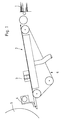
- Fig. 1 shows schematically a feed table of a sheet-fed offset printing press, in which paper sheets are conveyed in a known manner from a feed stack 1 onto the feed table.
- a suction belt conveyor 6 is provided in the feed table, which holds the paper sheet in a known manner by sucking the underside of the sheet onto the suction belts and by moving the suction belts on side marks 3, on which the paper sheets are aligned along their side edge, up to front marks 4, on which the paper sheets are conveyed aligned along their leading edge.
- the aligned paper sheets are transferred to subsequent cylinders 5 of a printing unit.
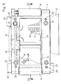
- FIGS. 2 to 4 show an embodiment of such a suction belt conveyor 6, in which 7 deflection rollers 8 and 9 are rotatably mounted parallel to each other in a frame.
- frame 7 two suction boxes 12 and 13 are attached.
- the suction boxes 12 and 13 each consist of a box 14 and 15 open at the top and are covered on their upper side by a cover plate 16 and 17 fastened thereon. Holes 18 are regularly distributed in the cover plates 16 and 17.
- a suction belt 10 is guided continuously, which rests with its upper run on the flat machined cover plates 16 and 17.
- opening channels 19 and 20 are guided continuously to the outside on both sides of the suction box 12 and 13, respectively, transversely to the sheet conveying direction.
- a sealing connection connection is created between opening channels 19 and 20 in the frame which run transversely to the sheet conveying direction and corresponding suction channels 22 provided in brackets 31, 32 for the table tops 11 laterally leading away from the frame
- the sealing effect is achieved by seals 30 around the opening area of the suction channel 22.
- the suction channels 22 lead below the cross members 25 into a common suction channel 29 to the suction air source, not shown.
- the already completely pre-assembled suction box module in this way consisting of frame 7 deflecting rollers 8, 9 suction boxes 12, 13 and suction belt 10 can be made ready for use exactly outside the table area unaffected by adjustment processes in the table.
- the complete suction box module can be made operational in a very short time by simply inserting the suction box module into the table niche provided and by fastening the frame 7 with the screws 27. From the suction air source, not shown, the suction boxes 13 and 14 via the suction channel 29, the suction channels 22 and 21 and the opening channels 19 and 20 are subjected to negative pressure. Through the openings 18 in the cover plates 16 and 17 and through the holes 26 of the suction belt, paper sheets lying on the suction belt can be conveyed exactly by moving the suction belt.
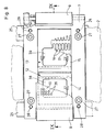
- FIGS. 5 to 7 show a further embodiment of such a suction belt conveyor.
- the opening channels 19 and 20 leading laterally out of the suction box are deflected downwards in the frame 7.
- the frame 7 is fastened on the longitudinal cross member 24, its outlet openings come out of the frame 7 in sealing contact with corresponding suction ducts 36 pointing upwards.
- These in turn open into a common suction duct 29, as shown in the exemplary embodiment in FIGS a suction air source, not shown, opens out.
- the corresponding openings of the suction channels 34, 36 or 33 and 35 which run perpendicular to the direction of insertion of the frame, namely perpendicularly downward towards the longitudinal cross member, enable the suction air connection between frame 7 and suction air source to be sealed in a particularly simple manner.
- the suction box module is sealed in the niche provided in the table by simply tightening the screws 27 on the longitudinal cross member 24.
- a suction belt conveying direction in which the suction air is supplied from a suction air source, not shown, via a suction channel 29 and suction channels 42, 43 connected to it, which pass through from below through the longitudinal cross member 24.
- the suction air passes from the suction channels 42, 43 via the lower run of the suction belt 10 and openings 38 and 39 in the bottom of the boxes 14 and 15 of the suction boxes 12 and 13 into the interior of the suction box.
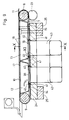
- Seals 40 and 41 extending transversely to the belt conveying direction are provided for sealing, as shown in FIGS. 9 and 11.
- a seal 40 is fastened on both sides in front of and behind the opening 45 or in front of and behind the opening 39 below the boxes 15 and 14 above the lower run of the suction belt in the frame 7.
- a seal 41 extending transversely to the belt conveying direction is fastened in front of and behind the opening of the suction channel 42 and the suction channel 43 in the belt conveying direction.
- the seals 40 and 41 are provided with two V-shaped sealing lips 44 and 45 which are spread apart upwards or downwards.
- the sealing lips are of a known type and can be provided, for example, from the material PTFE.
- the sealing lips are arranged in such a way that when the suction box module is attached to the longitudinal crossmember between the suction boxes and the suction belt, a sealing effect is created with the aid of the seals 40, and a sealing effect also arises between the suction belt and the longitudinal crossbar 24.
- a sealing lip 44 and a sealing lip 45 are arranged one above the other. The sealing lips are oriented in the direction of the strand movement direction.
- the deflection roller 8 mounted in the frame 7 for driving the suction belt with a gearwheel 46 which, when the suction belt module is introduced from above into the niche provided in the The contact table comes into meshing contact with a gearwheel 23 which is fastened to a drive shaft connected to the machine drive and mounted, for example, in the position 31 of the table or in the machine side frames.
- a driving claw 47 is fastened on the shaft of the deflection roller 8.
- the claw 47 comes into drive connection with a corresponding drive claw 48 of a drive shaft mounted in the machine side frame or in a holder 31 of the table top.
- the deflection roller 49 acting on the inside of the suction belt and the deflection roller 50 acting on the suction belt from the outside form a tensioning device, so that the web tension required for belt conveyance is only introduced into the intended position in the table niche when the suction belt module is introduced is produced.
- the assembly or disassembly of the suction belt can be simplified by such a device.
- Both described suction belt modules it is also possible to move an end-connectable suction belt in a known manner, but simply outside the feed table around the deflection rollers and to glue or weld its ends and then to connect and rework the joints at the best processing location .
- suction belts that are already manufactured.
- ribbons knitted all around in the application area of a sheet-fed offset printing press it is also conceivable for such a device to directly clamp and revise previously connected suction belts.
Landscapes
- Delivering By Means Of Belts And Rollers (AREA)
- Manual Feeding Of Sheets (AREA)
- Feeding Of Articles By Means Other Than Belts Or Rollers (AREA)
- Making Paper Articles (AREA)
Applications Claiming Priority (2)
| Application Number | Priority Date | Filing Date | Title |
|---|---|---|---|
| DE4243486 | 1992-12-22 | ||
| DE4243486A DE4243486C1 (de) | 1992-12-22 | 1992-12-22 | Anlegetisch einer Bogendruckmaschine |
Publications (3)
| Publication Number | Publication Date |
|---|---|
| EP0607577A2 true EP0607577A2 (fr) | 1994-07-27 |
| EP0607577A3 EP0607577A3 (fr) | 1994-08-10 |
| EP0607577B1 EP0607577B1 (fr) | 1998-05-13 |
Family
ID=6476123
Family Applications (1)
| Application Number | Title | Priority Date | Filing Date |
|---|---|---|---|
| EP93120242A Expired - Lifetime EP0607577B1 (fr) | 1992-12-22 | 1993-12-16 | Arrangement pour installer des bandes à vide dans des margeurs |
Country Status (4)
| Country | Link |
|---|---|
| US (1) | US5423255A (fr) |
| EP (1) | EP0607577B1 (fr) |
| JP (1) | JP2981388B2 (fr) |
| DE (2) | DE4243486C1 (fr) |
Families Citing this family (17)
| Publication number | Priority date | Publication date | Assignee | Title |
|---|---|---|---|---|
| DE4414441A1 (de) * | 1994-04-26 | 1995-11-02 | Heidelberger Druckmasch Ag | Anleger einer Maschine zur Bogenbearbeitung, insbesondere einer Bogendruckmaschine |
| JPH08127117A (ja) * | 1994-11-02 | 1996-05-21 | Komori Corp | エアシャッタ装置 |
| US5584246A (en) * | 1995-06-09 | 1996-12-17 | Werner Kammann Maschinenfabrik Gmbh | Process and apparatus for printing on flat individual articles |
| DE19623563C1 (de) * | 1996-06-13 | 1997-10-09 | Heidelberger Druckmasch Ag | Druckmaschine mit einem Bogentransportband |
| US6305285B1 (en) * | 1996-09-25 | 2001-10-23 | Crabtree Of Gateshead Ltd. | Sheet settling system |
| DE19701230C1 (de) * | 1997-01-16 | 1998-02-19 | Roland Man Druckmasch | Pneumatische Bogenleiteinrichtung in einer Druckmaschine |
| IT1305392B1 (it) * | 1998-09-11 | 2001-05-04 | Polielettronica S P A | Apparecchiatura per la riproduzione di una immagine su una carta ofoglio di materiale fotosensibile |
| JP3434252B2 (ja) * | 1999-11-08 | 2003-08-04 | シャープ株式会社 | 記録媒体搬送装置 |
| DE102005029532A1 (de) | 2005-06-25 | 2006-12-28 | Man Roland Druckmaschinen Ag | Bändertisch |
| JP2009161342A (ja) * | 2008-01-10 | 2009-07-23 | Seiko I Infotech Inc | 搬送体及び搬送装置 |
| US7988150B2 (en) * | 2009-02-24 | 2011-08-02 | Xerox Corporation | Media transport device with vacuum-controlled positioning |
| US8863939B2 (en) * | 2009-12-14 | 2014-10-21 | Xerox Corporation | Surface roughness for improved vacuum pressure for efficient media hold-down performance |
| US8695783B2 (en) * | 2009-12-14 | 2014-04-15 | Xerox Corporation | Vacuum transport belts |
| US8708135B2 (en) * | 2009-12-14 | 2014-04-29 | Xerox Corporation | Vacuum transport belts |
| EP2844459A1 (fr) * | 2012-05-03 | 2015-03-11 | Bobst Mex Sa | Machine de traitement d'elements en plaque avec table de marge munie de moyens de transport |
| DE202013103361U1 (de) * | 2013-07-25 | 2014-10-27 | Kilian Tableting Gmbh | Vorrichtung zum Zuführen von Einlegern |
| CN105858285B (zh) * | 2016-06-08 | 2017-06-30 | 三江学院 | 一种纸币铺平整理装置 |
Family Cites Families (23)
| Publication number | Priority date | Publication date | Assignee | Title |
|---|---|---|---|---|
| US2313100A (en) * | 1940-08-26 | 1943-03-09 | Miehle Printing Press & Mfg | Sheet feeding mechanism |
| GB938500A (en) * | 1961-09-23 | 1963-10-02 | Deritend Eng Co | Improved suction feed mechanism for cardboard and like blanks |
| US3648605A (en) * | 1971-03-29 | 1972-03-14 | William J Hottendorf | Box making machine |
| US3861669A (en) * | 1972-06-15 | 1975-01-21 | Tokyo Shibaura Electric Co | Apparatus for feeding sheet-like articles from a stack of articles |
| US3861259A (en) * | 1973-06-04 | 1975-01-21 | Harris Intertype Corp | Sheet delivery system |
| DE2452050C2 (de) * | 1974-11-22 | 1984-05-03 | M.A.N. Maschinenfabrik Augsburg-Nürnberg AG, 8900 Augsburg | Vorrichtung zum passergerechten Anlegen von Bogen in Bogenrotationsdruckmaschinen |
| US4512562A (en) * | 1980-04-09 | 1985-04-23 | Moll Richard J | Feeder table with photo-scan controlled belt motor |
| DE3138481C2 (de) * | 1981-09-28 | 1984-05-10 | M.A.N.- Roland Druckmaschinen AG, 6050 Offenbach | Vorrichtung zum Fördern eines geschuppten Stroms von Papierbogen |
| JPS58112742A (ja) * | 1981-12-25 | 1983-07-05 | Akiyama Insatsuki Seizo Kk | 枚葉印刷機の排紙機構に於ける印刷紙吸引装置 |
| JPS58158880A (ja) * | 1982-03-17 | 1983-09-21 | 阿部 和博 | 回転式同軸接栓 |
| DE3331662A1 (de) * | 1983-09-02 | 1985-03-28 | M.A.N.- Roland Druckmaschinen AG, 6050 Offenbach | Verfahren und vorrichtung zum passgenauen bogentransport in eine druckmaschine |
| JPS60171952A (ja) * | 1984-02-13 | 1985-09-05 | Fuji Xerox Co Ltd | 用紙搬送装置 |
| US4702471A (en) * | 1985-12-23 | 1987-10-27 | The Dow Chemical Company | Article transport arrangement |
| JPS62215447A (ja) * | 1987-03-04 | 1987-09-22 | Toshiba Corp | 用紙搬送装置 |
| JP2767290B2 (ja) * | 1989-07-05 | 1998-06-18 | 株式会社日立製作所 | 紙葉類反転装置 |
| US5098982A (en) * | 1989-10-10 | 1992-03-24 | The B. F. Goodrich Company | Radiation curable thermoplastic polyurethanes |
| US5197812A (en) * | 1989-11-09 | 1993-03-30 | Dataproducts Corporation | High accuracy vacuum belt and pinch roller media transport mechanism |
| DE4004351C2 (de) * | 1990-02-13 | 1996-05-23 | Heidelberger Druckmasch Ag | Anlegetisch einer Bogendruckmaschine |
| DE4012948A1 (de) * | 1990-04-24 | 1991-10-31 | Roland Man Druckmasch | Vorrichtung zum foerdern von druckbogen |
| DE4013302A1 (de) * | 1990-04-26 | 1991-10-31 | Koenig & Bauer Ag | Vorrichtung zum foerdern eines insbesondere geschuppten stroms von bogen |
| US5026038A (en) * | 1990-05-17 | 1991-06-25 | Mccain Manufacturing Corporation | Signature feeder operable with either flat or standing stacks |
| US5199608A (en) * | 1990-10-09 | 1993-04-06 | Different Dimensions, Inc. | Garment hanger with irremovable information tabs |
| DE4126546C1 (fr) * | 1991-08-10 | 1992-10-01 | Man Roland Druckmaschinen Ag, 6050 Offenbach, De |
-
1992
- 1992-12-22 DE DE4243486A patent/DE4243486C1/de not_active Expired - Fee Related
-
1993
- 1993-12-16 DE DE59308545T patent/DE59308545D1/de not_active Expired - Lifetime
- 1993-12-16 EP EP93120242A patent/EP0607577B1/fr not_active Expired - Lifetime
- 1993-12-21 JP JP5322114A patent/JP2981388B2/ja not_active Expired - Lifetime
- 1993-12-22 US US08/173,629 patent/US5423255A/en not_active Expired - Lifetime
Also Published As
| Publication number | Publication date |
|---|---|
| US5423255A (en) | 1995-06-13 |
| EP0607577B1 (fr) | 1998-05-13 |
| JP2981388B2 (ja) | 1999-11-22 |
| JPH06219606A (ja) | 1994-08-09 |
| DE59308545D1 (de) | 1998-06-18 |
| DE4243486C1 (de) | 1994-04-07 |
| EP0607577A3 (fr) | 1994-08-10 |
Similar Documents
| Publication | Publication Date | Title |
|---|---|---|
| DE4243486C1 (de) | Anlegetisch einer Bogendruckmaschine | |
| DE19914178B4 (de) | Bogenleiteinrichtung in einer Bogendruckmaschine | |
| EP3150521B1 (fr) | Dispositif de groupement d'articles et procede de changement de format d'un tel dispositif | |
| EP0740608B1 (fr) | Dispositif de montage, de demontage et de transport d'objets courbes faciles a plier et pourvus de rebords de suspension | |
| EP0470362B1 (fr) | Machine pour traiter des feuilles et dispositif, associé à cette machine, pour transporter des piles de feuilles | |
| DE10047395A1 (de) | Bogentransportsystem für eine Rotationsdruckmaschine | |
| DE4424931C2 (de) | Vorrichtung zur Montage, Demontage und Transport von leicht biegbaren, bogenförmigen Gegenständen mit Einhängeabkantungen | |
| EP0740607B1 (fr) | Dispositif pour le montage, le demontage et le transport d'objets courbes facilement pliables pourvus d'aretes d'accrochage | |
| DE102011107799A1 (de) | Transportvorrichtung | |
| DE102004030277A1 (de) | Verfahren zur Förderung von Bogen durch eine drucktechnische Maschine und Vorrichtung zur Durchführung des Verfahrens | |
| EP0749831A1 (fr) | Dispositif pour changer les clichés d'impression aux unités d'impression de machines à imprimer | |
| EP1775115B1 (fr) | Dispositif pour la fabrication de carton ondulé | |
| DE19856372B4 (de) | Bogentransportband | |
| DE102010002500A1 (de) | Vorrichtung zum Handhaben, nämlich zum Führen und/oder Bremsen, von Bogen in einer bogenverarbeitenden Maschine | |
| DE102006013955B3 (de) | Einrichtungen zum Zuführen einer Materialbahn zu einer Druckeinheit | |
| DE19502240C3 (de) | Verfahren und Vorrichtung zum Einziehen einer Bedruckstoffbahn im Rollenrotationsdruck | |
| DE102011118905B4 (de) | Bearbeitungsstation für eine Stanzmaschine | |
| EP2141101B1 (fr) | Dispositif d'aspiration de tableau en tôle et dispositif de transport de tableaux en tôle dans une machine d'impression de tôle ou une machine de laquage de tôle | |
| DE102011109085A1 (de) | Bogenstanz- und/oder - prägestation mit druckluftbetätigtem Schließrahmen | |
| DE102012013757A1 (de) | Werkzeugaufnahmevorrichtung | |
| DE10246297B4 (de) | Niederhaltereinrichtung in der Bogenanlage | |
| EP0623533A1 (fr) | Procédé et dispositif de transport pour transporter des porte-pièces | |
| DE102004053099B4 (de) | Verfahren zur Glättung eines Bogens aus Bedruckstoff | |
| DE102006051278B4 (de) | Vorrichtung und Verfahren zur veredelnden Bearbeitung von bogenförmigen Substraten in einer Bogendruckmaschine | |
| DE202019101925U1 (de) | Vorrichtung zum Fördern einer Materialbahn |
Legal Events
| Date | Code | Title | Description |
|---|---|---|---|
| PUAI | Public reference made under article 153(3) epc to a published international application that has entered the european phase |
Free format text: ORIGINAL CODE: 0009012 |
|
| PUAL | Search report despatched |
Free format text: ORIGINAL CODE: 0009013 |
|
| 17P | Request for examination filed |
Effective date: 19931216 |
|
| AK | Designated contracting states |
Kind code of ref document: A2 Designated state(s): CH DE FR GB LI |
|
| AK | Designated contracting states |
Kind code of ref document: A3 Designated state(s): CH DE FR GB LI |
|
| GBC | Gb: translation of claims filed (gb section 78(7)/1977) | ||
| 17Q | First examination report despatched |
Effective date: 19970418 |
|
| GRAG | Despatch of communication of intention to grant |
Free format text: ORIGINAL CODE: EPIDOS AGRA |
|
| GRAG | Despatch of communication of intention to grant |
Free format text: ORIGINAL CODE: EPIDOS AGRA |
|
| GRAH | Despatch of communication of intention to grant a patent |
Free format text: ORIGINAL CODE: EPIDOS IGRA |
|
| GRAH | Despatch of communication of intention to grant a patent |
Free format text: ORIGINAL CODE: EPIDOS IGRA |
|
| GRAA | (expected) grant |
Free format text: ORIGINAL CODE: 0009210 |
|
| AK | Designated contracting states |
Kind code of ref document: B1 Designated state(s): CH DE FR GB LI |
|
| REG | Reference to a national code |
Ref country code: CH Ref legal event code: EP |
|
| REF | Corresponds to: |
Ref document number: 59308545 Country of ref document: DE Date of ref document: 19980618 |
|
| GBT | Gb: translation of ep patent filed (gb section 77(6)(a)/1977) |
Effective date: 19980702 |
|
| ET | Fr: translation filed | ||
| PLBE | No opposition filed within time limit |
Free format text: ORIGINAL CODE: 0009261 |
|
| STAA | Information on the status of an ep patent application or granted ep patent |
Free format text: STATUS: NO OPPOSITION FILED WITHIN TIME LIMIT |
|
| 26N | No opposition filed | ||
| REG | Reference to a national code |
Ref country code: GB Ref legal event code: IF02 |
|
| PGFP | Annual fee paid to national office [announced via postgrant information from national office to epo] |
Ref country code: GB Payment date: 20021125 Year of fee payment: 10 |
|
| PG25 | Lapsed in a contracting state [announced via postgrant information from national office to epo] |
Ref country code: GB Free format text: LAPSE BECAUSE OF NON-PAYMENT OF DUE FEES Effective date: 20031216 |
|
| GBPC | Gb: european patent ceased through non-payment of renewal fee |
Effective date: 20031216 |
|
| PGFP | Annual fee paid to national office [announced via postgrant information from national office to epo] |
Ref country code: FR Payment date: 20061212 Year of fee payment: 14 |
|
| PGFP | Annual fee paid to national office [announced via postgrant information from national office to epo] |
Ref country code: CH Payment date: 20061215 Year of fee payment: 14 |
|
| REG | Reference to a national code |
Ref country code: CH Ref legal event code: PL |
|
| PG25 | Lapsed in a contracting state [announced via postgrant information from national office to epo] |
Ref country code: LI Free format text: LAPSE BECAUSE OF NON-PAYMENT OF DUE FEES Effective date: 20071231 Ref country code: CH Free format text: LAPSE BECAUSE OF NON-PAYMENT OF DUE FEES Effective date: 20071231 |
|
| REG | Reference to a national code |
Ref country code: FR Ref legal event code: ST Effective date: 20081020 |
|
| PG25 | Lapsed in a contracting state [announced via postgrant information from national office to epo] |
Ref country code: FR Free format text: LAPSE BECAUSE OF NON-PAYMENT OF DUE FEES Effective date: 20071231 |
|
| PGFP | Annual fee paid to national office [announced via postgrant information from national office to epo] |
Ref country code: DE Payment date: 20110125 Year of fee payment: 18 |
|
| REG | Reference to a national code |
Ref country code: DE Ref legal event code: R119 Ref document number: 59308545 Country of ref document: DE Effective date: 20120703 |
|
| PG25 | Lapsed in a contracting state [announced via postgrant information from national office to epo] |
Ref country code: DE Free format text: LAPSE BECAUSE OF NON-PAYMENT OF DUE FEES Effective date: 20120703 |