EP0607586A1 - Procédé et appareil pour chauffer à micro-ondes - Google Patents
Procédé et appareil pour chauffer à micro-ondes Download PDFInfo
- Publication number
- EP0607586A1 EP0607586A1 EP93120410A EP93120410A EP0607586A1 EP 0607586 A1 EP0607586 A1 EP 0607586A1 EP 93120410 A EP93120410 A EP 93120410A EP 93120410 A EP93120410 A EP 93120410A EP 0607586 A1 EP0607586 A1 EP 0607586A1
- Authority
- EP
- European Patent Office
- Prior art keywords
- temperature
- high frequency
- heated
- heating
- time
- Prior art date
- Legal status (The legal status is an assumption and is not a legal conclusion. Google has not performed a legal analysis and makes no representation as to the accuracy of the status listed.)
- Granted
Links
Images




Classifications
-
- H—ELECTRICITY
- H05—ELECTRIC TECHNIQUES NOT OTHERWISE PROVIDED FOR
- H05B—ELECTRIC HEATING; ELECTRIC LIGHT SOURCES NOT OTHERWISE PROVIDED FOR; CIRCUIT ARRANGEMENTS FOR ELECTRIC LIGHT SOURCES, IN GENERAL
- H05B6/00—Heating by electric, magnetic or electromagnetic fields
- H05B6/64—Heating using microwaves
- H05B6/66—Circuits
- H05B6/68—Circuits for monitoring or control
- H05B6/687—Circuits for monitoring or control for cooking
-
- H—ELECTRICITY
- H05—ELECTRIC TECHNIQUES NOT OTHERWISE PROVIDED FOR
- H05B—ELECTRIC HEATING; ELECTRIC LIGHT SOURCES NOT OTHERWISE PROVIDED FOR; CIRCUIT ARRANGEMENTS FOR ELECTRIC LIGHT SOURCES, IN GENERAL
- H05B6/00—Heating by electric, magnetic or electromagnetic fields
- H05B6/64—Heating using microwaves
- H05B6/6447—Method of operation or details of the microwave heating apparatus related to the use of detectors or sensors
- H05B6/645—Method of operation or details of the microwave heating apparatus related to the use of detectors or sensors using temperature sensors
-
- H—ELECTRICITY
- H05—ELECTRIC TECHNIQUES NOT OTHERWISE PROVIDED FOR
- H05B—ELECTRIC HEATING; ELECTRIC LIGHT SOURCES NOT OTHERWISE PROVIDED FOR; CIRCUIT ARRANGEMENTS FOR ELECTRIC LIGHT SOURCES, IN GENERAL
- H05B6/00—Heating by electric, magnetic or electromagnetic fields
- H05B6/64—Heating using microwaves
- H05B6/6447—Method of operation or details of the microwave heating apparatus related to the use of detectors or sensors
- H05B6/645—Method of operation or details of the microwave heating apparatus related to the use of detectors or sensors using temperature sensors
- H05B6/6452—Method of operation or details of the microwave heating apparatus related to the use of detectors or sensors using temperature sensors the sensors being in contact with the heated product
-
- H—ELECTRICITY
- H05—ELECTRIC TECHNIQUES NOT OTHERWISE PROVIDED FOR
- H05B—ELECTRIC HEATING; ELECTRIC LIGHT SOURCES NOT OTHERWISE PROVIDED FOR; CIRCUIT ARRANGEMENTS FOR ELECTRIC LIGHT SOURCES, IN GENERAL
- H05B6/00—Heating by electric, magnetic or electromagnetic fields
- H05B6/64—Heating using microwaves
- H05B6/6447—Method of operation or details of the microwave heating apparatus related to the use of detectors or sensors
- H05B6/645—Method of operation or details of the microwave heating apparatus related to the use of detectors or sensors using temperature sensors
- H05B6/6455—Method of operation or details of the microwave heating apparatus related to the use of detectors or sensors using temperature sensors the sensors being infrared detectors
Definitions
- the present invention generally relates to a microwave heating method and apparatus for effecting a vacuum cooking operation (sous vide) with high frequency heating.
- the vacuum cooking operation is to cook at a constant temperature between approximate 55°C and approximate 95°C vacuum packed foods by water boiling or steam oven. It has following advantages.
- a heat conduction operation is superior because of vacuum. A uniform heating operation can be effected with a specific temperature which ensures the most delicious taste with respect to foods.
- B) The permeation of seasonings is superior because of the vacuum. The seasoning can be effected with a small amount of sugar, salt, thus being desirable for the health.
- C Food is vacuum packed so that the flavor is not damaged.
- D Food is heated at low temperatures so that lines, fibers and so on are soft without becoming hardened.
- E A yield is considerably higher, because food is cooked at temperatures where water division of protein is not caused.
- Foods can be preserved for approximately one week in cold storage so that mass supply of foods for banquets at a hotel can be conveniently provided. The vacuum cooking is invented in France and is spread quickly.
- Humidity environment of a kitchen where hot water of 60°C through 95°C is kept is not favorable as judged easily from the humidity environment within the bath chamber of 42°C through 43°C in hot water temperature.
- the environment has a risk of being dangerous enough to cause burns. Therefore, improvements in it is strongly desired. As a fuel expenditure becomes large to maintain the hot temperatures, it is desired to be improved. These situations are much alike even in the steam ovens.
- the uniform heating method by the conventional art can be chiefly classified into four.
- the temperature of the food is detected so as to control the wave application.
- patents such as the USP 3,634,652 (foods are retained at a given temperature or lower with the use of a sensor), and the USP 4,785,824 (optical fiber thermometer is used) in addition to the USP 2,657,580 (multirange thermometer).
- Japanese Patent Laid-Open publication No. 52-17237 a plurality of locations in food are detected in temperature, the wave output is lowered at a time point when one has reached the set temperature, and the heating is completed at a time point when the other has reached the set temperature), or the like even in Japanese Patent.
- Japanese Patent Laid-Open Publication No, 54-7641 a method of estimating the inter temperature from the food surface temperature, a wave irradiation stop when the surface temperature has reached 5°C at the defrosting time of the frozen food, a wave application is effected again at a time as low as 0°C, differentiation values in time change from 5°C to 0°C are detected) or the like.
- each portion of the food can be measured correctly as a combination art, it can be easily realized by an advanced controlling method using computers in an estimation controlling operation or the like. However, only one portion becomes 65°C if a heating operation is effected to, for example, 65°C, or the other portion remains as it is left cold without being heated (described later in detail).
- latent heat of 80 calories in 0°C becomes a buffer in the defrosting operation.
- the difference to the desired temperature of the finishing is large and also, the temperature difference of each portion of the food is also large, because there are various dispersions even in the application of it to the vacuum cooking portion.
- +10°C or -10°C dispersion is caused in the interior of the food by the heating operation with -0°C as a target in, for example, defrosting operation, the + side results between - 10°C through 0°C, because 0°C is maintained while the latent calory does not exceed 80 calory.
- a heating operation is effected with, for example, a finish temperature of 65°C as a target, and unequality of +10°C or -10°C is caused, the dispersion becomes 55°C through 75°C.
- a flat food like a flat tongue becomes more uniform so that it is said to be completely unsuitable for a high frequency heating operation.
- the present invention has been developed with a view to substantially eliminating the above discussed drawbacks inherent in the prior art and has for its essential object to provide an improved microwave heating method and apparatus.
- Another important object of the present invention is to contract the temperature difference between a desired finish temperature and each portion of a food by 1°C and by approximately several °C at maximum.
- the present invention takes the following means.
- a high frequency heating apparatus comprising a heating chamber for accommodating the heated, a high frequency irradiation source for irradiating the high frequency into the heating chamber, a surface temperature detecting means for detecting the temperature of the substantial surface of the heated, a central portion temperature detecting means for detecting the temperature of the central portion neighborhood of the heated, a controlling circuit for controlling the high frequency irradiation source, and which is characterized in that the high frequency is adapted to apply when all three conditions, while the difference between the surface temperature and the central temperature does not exceed a constant value, while the surface temperature does not exceed the finish temperature of the heated, and while the central temperature is lower by 1°C through several °C from the finish temperature, are satisfied. Also, it is a heating method of carrying out the heating operation the same as it without the use of the temperature detecting means.
- the method comprises the steps of popularizing it, time dividing, along a type of exponential function for expressing the thermal conduction within the heated, the necessary minimum high frequency energies.
- a surface temperature detecting means of the heated is adopted, the above described exponential function is approximated with at least three linear segments, energies E2 and E1 per unit time equal to each slope of two straight line segments are adapted to be applied till a temperature T2 corresponding to the intersecting point of two straight segments of the latter half and a temperature T1 corresponding to the finish temperature of the heated.
- the heated food is grasped with a sandwich shape with an oil mat with edible oil being desired, sealed within a thin plastic film made bag as heating auxiliary tool.
- a high frequency heating apparatus comprising a heating chamber for accommodating the heated, a high frequency irradiation source for accommodating the high frequency within the heating chamber, a surface temperature detecting means for detecting the temperature of the substantial surface of the heated, a central portion temperature detecting means for detecting the temperature of the central portion neighborhood of the heated, a controlling circuit for controlling the high frequency irradiation source, and which is characterized in that high frequency waves are adapted to be applies when all three conditions while the difference between the surface temperature and the central temperature does not exceed a constant value, while the surface temperature does not exceed the finish temperature of the heated, and while the central temperature is lower by 1°C through several °C than the finish temperature.
- the high frequency application is effected only while a surface temperature and a central temperature of first conditions do not exceed a constant value, for example, 20°C, the temperature unequality of the interior of the heated caused by the high frequency application is eased by the internal heat conduction during the application stop so as to raise the temperature of the central portion.
- a constant value for example, 20°C
- the temperature of each portion of the heated does not exceed the finish temperature.
- the temperature of the central portion is raised by the internal heat conduction of the heated.
- the temperature of the central portion tolerates a temperature lower by 1°C than the finish temperature or some unequality by third conditions, the high frequency application is continued before it reaches a temperature lower by several degrees C.
- the interior of the heated becomes as uniform as 1°C or several °C in temperature difference.
- the surface temperature detecting means of the heated is adopted, the above described exponential function is approximated with at least three straight line segments, energies E2 and E1 per unit time equal to each slope of two straight line segments are adapted to be applied till a temperature T2 corresponding to the intersecting point of two straight segments of the latter half and a temperature T1 corresponding to the finish temperature of the heated.
- the temperature reaches a set temperature in a short time when the output of the high frequency heating apparatus is larger. It tales a long time to reach the set temperature when the output is small so that the variation of the output is corrected and the heating operation is uniformly effected.
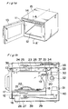
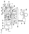
- Fig. 1 shows a perspective view (a) showing an outer appearance of a high frequency heating apparatus of the present invention and a sectional view taken along a line A-A' thereof.
- the frequency wave heating apparatus is composed, in outer appearance, of a stainless mesh made heating chamber 11, a crystallizing glass made food placement board 12 fixed on the lower portion, a door 13 for closing a heating chamber opening, an operating portion 14 provided on the upper portion of the door, an outer box 15 for covering periphery, or the like.
- a sectional view thereof will be described hereinafter.
- An oil mat 16 is placed on a food placement board 12 and a wire rack 17 is placed on it. Only an accompanying multicore shielding wire 18, a metallic plug 19 provided on its tip, and a metallic connector 20 fixed onto a rear face wall of the heating chamber are described here.
- the wire rack will be described later in detail.
- the plug 19 and the connector 20 are connected to fit with each other.
- a pair of metallic plug and connector for RS-232C use which are widely used in personal computers at present are adopted.
- the heated food 21, for example, a flat shaped tongue flounder, is placed on the wire rack 17.
- An oil mat 22 is further placed on it.
- a resin made stirrer cover 23 is fixed in the upper portion of the heating chamber.
- An antenna 24 and a motor 25 for rotation use thereof are secured in the upper portion.
- an antenna 26 and a motor 27 for its rotation use are secured even under the food placement board 12.
- a waveguide 28 is provided on the top face of the heating chamber and a waveguide 29 is provided on the bottom face.
- a magnetron 30 is provided at the end of the waveguide 28 and a magnetron 31 is provided at the end of the waveguide 29. Each waveguide connects the magnetron with an antenna.
- a fan motor 32 is provided with an view of causing the magnetron 30 to be air-cooled.
- One portion of the cooling winds passes through the magnetron 30 and thereafter is exhausted from an exhaust perforated group 33.
- One portion thereof is exhausted outsides through an air guide 34, a perforation group 35 provided in the rear face wall of the heating chamber, a perforation group 36 provided close to the door of the stirrer cover, an exhaust perforation group, an exhaust guide 37 provided in the top face wall of the heating chamber not described in Fig. 1 and a perforation group 38 provided in the rear face walls of the heating chamber.
- Outside cold winds are penetrated from the perforation group 39 provided in the bottom walls of the outer box and are absorbed into the fan motor 32.
- a fan motor (not shown) for cooling the magnetron 31 is also provided so that the winds are exhausted from the exhaust perforation group 40 provided in the reverse face wall of the outer box.
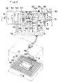
- Fig. 2 is a perspective view (a) of a wire rack 17, and a sectional view (b) taken along a line B-B' thereof.
- the wire rack is composed of a square shaped frame 41 of a metallic round rod, an empty circular metallic rod body 42 fixedly inserted into a non-perforated hole which is opened from behind into the front side of the frame and a through hole which is opened longitudinally through to the rear side of the frame, a thermistor 43 inserted into the interior, a pair of mounting metal fittings 44 and 45 fixed in a condition for grasping the rear side of the frame, a vis 46 for fixing them, the multicore shielding wire 18 and the metallic plug 19.
- the rod shaped body 42 is a metallic tube, approximately 1.3 mm in inside diameter, 0.18 in thickness, which is made by the same making method as that of, for example, an injection needle.
- the rod shaped body is fixedly mounted on the frame 41.
- the rod shaped body together with it is nickel-plated.
- a thermistor 43 can be inserted in size into the tube.
- Two lead wires are insulted in a range positioned within at least rod grasped body 42 and are electrically connected with one core wire of the multicore shielding wire 18 within a space of a triangle to be formed with the frame 41, and a pair of mounting metallic fittings 44 and 45.
- a concave portion is provided in the center of the mounting metallic fittings 44 and 45.
- a metallic housing of the multicore shielding wire is grasped so as to effect the electric connection at the same time.
- the metallic plug 19 is also electrically connected with the metallic housing of the shielding wire.
- the thermistor 43, and its lead wires and so on are electrostatically shielded with the rod shaped body 42, the mounting metallic fittings 44, 45, the metallic housing of the shielding wire and the metallic plug.
- seven thermistors 43 are used. They are positioned near the center of the rods, which are the central seven rods of the seventeen rod shaped bodies drawn in Fig. 2.
- Fig. 3 shows an electric circuit diagram, in the present embodiment, showing the combination of the wire rack 17 and the heated food 21 placed on it, and the whole electrical signals. It is connected with a lamp 54 for illumination of the heating chamber and its relay 55 for ON-OFF use through a fuse 52, a coil 53 for noise filter use from a power plug 54. It is connected with a heater transformer 56 for magnetron use and its relay for ON-OFF use. Motors 25 and 27 for antenna rotation illustrated in Fig. 1 in series with the heater transformer are connected with a fan motor 32 for magnetron cooling use and a fan motor 58 not illustrated in Fig. 1. It is branched into two.
- Switches 60 and 61 interlocked with the opening and closing of the door are connected in the respective branch path with the main relays 62 and 63.
- short switches 64 and 65 are switched.
- Triode AC switches 66 and 67 are connected.
- high-tension transformers 68 and 69 are connected.
- Magnetrons 30 and 31 are connected through a condenser and a diode onto the secondary side of the high tension transformer.
- the trigger circuit 70 and 71 are connected to gate of the triode AC switches so as to connect with the controlling circuit 72.
- the coils of the above described all the relays 55, 57, 62 and 63 are connected with the controlling circuit 72, likewise.
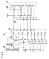
- Fig. 4 is a circuit diagram of a controlling circuit 72.
- the primary side of the transformer 73 is connected behind the coil 53 of Fig. 3.
- One on the primary side is rectified, smoothed so as to generate direct current 18V and stabilized direct current 5V. They are added to the VCC and VSS terminal of the microprocessor 74.
- the waveform before the rectification on the secondary side is shaped by the transistor 75 and is inputted to one terminal (it is referred to as P8) of the microprocessor 74.
- the above described seven thermistors 43 are connected in series with a fixed resistance 76 into direct current + 5V.
- a connecting point with the fixed resistance is connected with the A / D conversion function attached input terminals P1 to P7 of the microprocessor.
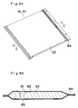
- Fig. 5 is a perspective view (a) of an oil mat 16 or 22, and a sectional view taken along a line of C-C' thereof. It is a square type bag shaped container 82 of thin flexible resin film composed of polyethylene layer 80 of approximately 50 micron inside and a nylon layer 81 of approximately 20 micron outside.
- the square bag shaped container has edible oil 83 such as salad oil or the like put on the market therein and has an entrance portion 84 thermally sealed after being desired.
- Fig. 6 is an electric circuit diagram in another embodiment which corresponds to the above described Fig. 3.
- a personal computer 90 is used instead of the controlling circuit and an optical fiber thermometer 92 is connected through RS-232C cable 91 from the personal computer.
- An optical fiber type temperature sensors 93 and 94 are mounted on a thermometer 92.
- Two sensors 93 and 94 are guided into a heating chamber through orifices opened in the side wall of the above described heating chamber 11 and are inserted into the heated food 21 (not shown).
- a note type personal computer PC-9801NS / T manufactured by NEC is used.
- Specific note station and input, output board such as MM-86, PI016I manufactured MSE are used or interface with resect to the relay.
- a model 755 manufactured by Lackstron is used as an optical fiber thermometer.
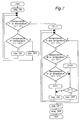
- Fig. 7 is a schematic flow of a control program to be used by the personal computer in the embodiment having the electric circuit of Fig. 6.
- a first temperature sensor 93 of the optical fiber thermometer is inserted into a portion where the heated food becomes highest at temperature, generally into the surface of the heated food. The temperature is assumed to be H.
- a second temperature sensor 94 is inserted into a portion where the temperature becomes lowest, generally into the center and its vicinity of the heated food. The temperatures is assumed to be L. In order to know the highest, lowest temperature portions in advance, properly heat the food of the same shape and the temperature of each portion has only to be checked.
- the desired finish temperature LT1 of the heated food and a temperature LT2 lower by 1°C or by several °C than it are input into a personal computer so as to memorize them. As this fact is well known, it is omitted. Its subsequent high frequency application start will be described. Depress a start key and all the relays (55, 57, 62 and 63) are turned on. In the flow, check that both the temperature H and the temperature L are both the above described LT2 or lower. When they are lower, a step advances onto a T side. Reference character T stands for True and means that a proposition is correct. When the proposition is wrong, a step is adapted to advance onto F (False) side. Check that the difference between the temperature H and the temperature L is, for example, 20°C or lower. When it is lower, a step advances to the lower T side so as to turn on two triode AC switches 66 and 67.
- a step returns upwards so as to pass two temperature checks LT2 or lower and 20°C or lower.
- a step advances onto the F side so as to turn off the triode AC switches. While the ON-OFF of the triode AC switches are repeated in this manner, the temperature H reaches the temperature HT2.
- a step advances onto a F side and advances onto the right side of the flow.
- a D flag is made 1. Then, both the temperature H and the temperature L are confirmed not to be LTH2 or more. When either of them is LT2 or lower, a step advances onto the lower T side. Then, it is checked that both are also LT1 or lower. When both are lower, a step advances onto the lower T side. Then, it is checked that both of them are LT2 or lower. A step advances onto the F side (right side), because the temperature H has been reached so as to check that a D flag is 0. As the D flag has been just equalized to 1, a step advances onto the side (left side) so as to turn on the triode AC switches.
- a step returns upwards again so as to pass three temperature checks.
- a step advances to the F side (right side) so as to turn the D flag into 0.
- the step advances downwards so as to receive the check of the D flag and advances a T side so as to turn off the triode AC switches.
- a step returns upwards again and passes three temperature checks. Since the D flag remains 0 if temperature H is LT2 or more this time, the triode AC switches remains off.
- a step advances to a T side, and advances downwards. The D flag becomes 1.
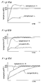
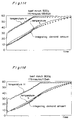
- Fig. 8 is a graph showing the relation between time and temperature in a case where pork of approximately 900 grams frozen to approximately 0°C through 5°C is heated to 65°C of a desired finish temperature.
- the graph shows results where 65°C is inputted as a desired finish temperature LT1, 64°C is inputted as its lower temperature LT2, and the pork is heated.
- An oil mat is used in a plate shape of approximately 1 cm in thickness.
- Salad oil of 500 grams is sealed, desired into a bag of approximately 23 cm in width, approximately 30 cm in length, and 0.1 mm in film thickness. Two bags are used to grasp the pork in a sandwich shape from above and below.
- Heating time is two hours and thirty minutes.
- An integrating power value measured on the primary side of the transformers 68 and 69 is 136 wh, the temperature of respective portions of the pork is between 64°C through 66°C. It is within the difference 1°C or lower with respect to the finish (desired) temperature 65°C.
- An optical fiber thermometer can measure the temperatures even in the irradiation environment of the high frequency. Relatively correct temperatures can be measured.
- the measured system is less in turbulence. Namely, only the inserted portion thereof is not excessively heated by the insertion thereof into the food. It is considered that a uniform heating operation can be easily realized by the high frequency within 1°C in temperature difference of each portion of the heated food by the combination between the optical fiber thermometer and the control art as described in the conventional art. Actually it cannot be realized.
- Table 1 shows the relation between input power quantity (integrating power quantity) in the above described heating operation and the absorption heat quantity of the heated food.
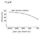
- Fig. 12 is load fluctuation characteristics of the high frequency heating apparatus output used for the calculation.
- Table 1 Quality /Weight Minced Beef Pork 100g 200g 500g 800g 900g Temperature[°C] 5-58 5-58 5-58 5-58 5-65 1. Heat quantity of meat, oil mat 29.8wh 32.7wh 41.4wh 50.1wh 49.8wh 2. Heat quantity of water equivalent to meat 6.1wh 12.3wh 30.8wh 49.3wh 62.7wh 3. Irradiation power quantity 23.5wh 41wh 89.6wh 113wh 136wh 4. Corrected value of the above 7.9wh 18.0wh 46.5wh 59.8wh 70.7wh 2/4 77% 68% 66% 82% 88%
- Calculation is effected as described hereinabove with the specific heat of the beef as approximately 0.43 so as to obtain the (1) line of Table 1.
- the (2) line shows heat quantity of water equivalent in weight to meat. It is assumed to be an absorption heat quantity. The value is adopted, because an approximately similar tendency is provided (description is omitted) even when the oil mat is not used.
- the irradiation (input) power quantity of the (3) line is a value on the primary side of the transformer as described hereinabove.
- the 20°C controlling operation When the 20°C controlling operation is not introduced, it is considered that the irradiated energies are consumed except for the heat conduction of the heated food interior. For example, the heat of the surface portion excessively heated is emitted into air. The heat is hardly conducted into the interior of the food.
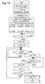
- the control program flow of Fig. 14 is applicable to a high frequency heating apparatus having circuits where an optical fiber thermometer is omitted from the electric circuit diagram of Fig. 6.
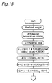
- the weight of the heated food which is assumed to be w
- desired finish temperature rise a value where an initial temperature ⁇ o is subtracted from the desired finish temperature ⁇ 1 of the food is assumed to be ⁇
- a heating time which is assumed to be ⁇
- the calculating operation is effected (basic is basically used in expression).
- a desired temperature rise value ⁇ is multiplied by food weight w. It is multiplied by 1.25 in anticipation of the above described 25 % loss. It is divided by 860 for conversion into the power quantity.
- the high frequency power quantity to be irradiated into the hating chamber can be calculated by the calculation provided so far.
- the time distribution is effected in accordance with the above described exponential function, it is realized by the combination between the short time irradiation and the irradiation stop in terms of software, because an appliance capable of non-stage power adjustment is very difficult to make in terms of hardware. It is divided by nominal high frequency output value (rated output value) for calculation of the irradiation total time and is multiplied by 3,600 seconds. The irradiation time is made constantly 3 seconds where favorable results are obtained by experiments. It is divided by 3 and the fractions are emitted. A Yen mark shows division thereof (however, expression peculiar to Japan). The total frequency no of three second irradiation is obtained by it.
- the food is put into the heating chamber in this condition. Wait for the start key to be depressed. After the depression thereof, turn on, first, a relay so as to store undefined t o as 0.
- a heating operation is effected with the use of the control program.
- the temperature difference of the interior of the food is small and the temperature of the food varies each time.
- Change the above described loss 25 % like, for example, 15% or 35% with the use of the same food as in material quality and shape so as to repeat trial and error often and the temperature becomes closer to the desired temperature. But it is difficult to stably have difference within 1°C.
- a method of controlling high frequency irradiation quantity while monitoring the temperature of the heated food is required.
- a thermistor within the wire rack is provided for the object.
- the high frequency irradiation quantity is distributed in time along the exponential function, namely, curve line.
- the curve line is approximated with about three straight line segments and the temperature in the intersecting points of the straight lines is monitored so that the controlling operation is easy to effect.
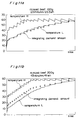
- the curve line is approximated with three straight line segments with Fig. 10 as reference.
- the exponential function passes one tenth of the heating time, approximately one third of the temperature rise and three tenths of the heating time, approximately two thirds of the temperature rise, the straight lines are three with two becoming intersecting points.
- high frequency irradiation time is all three seconds and the irradiations stop time is respectively A, B or C seconds.
- Fig. 16 a schematic flow of a control program after the start key has been depressed. Confirming that the output value (voltage value showing the thermistor 43 provided on the wire wrack 17) of the food surface temperature detecting means does not reach the T / 10 (T3), first, all the relays are turned on. Periodic operations (which are assume to be high frequency energies of E3 per unit time) of three seconds on, A second off are continuously repeated. T is a value where the value T o initial (before the heating) of the food has been subtracted from the output value T1 when the heated food whose temperature reaching the finish temperature ⁇ 1 is measured by the food surface temperature detecting means. A step advances onto the F side after the output value has reached the T / 10 (T3).
- a periodic operation (which is assumed to be high frequency energies of E2 per unit time) of three seconds on, B seconds off is continuously repeated. After it has reached, a step advances onto the F side. Confirming that it has not reached T1 this time, a periodic operation (likewise, E1) of three second on, c second off are continuously repeated. After it has reached, a step advances onto the F side. All the relays are turned off so as to come to end.
- the difference 1°C or lower with respect to the desired temperature is stably obtained as in a case where a optical fiber shown in Fig. 6 is used when a cooking operation is effected by a method of the sectional view shown in Fig. 1 with the use of the control program by the flow.
- the uniform heating operation is realized by the combination between the food surface temperature detecting means and the high frequency energies distribution along the straight line segments approximate to the functions showing the heat conduction of the food interior.
- a method of measuring the surface (the highest temperature) portion and the central (the lowest temperature) portion of the above described (2) paragraph and controlling the high frequency application while retaining the difference between them substantially under a constant value or lower is not inferred from the conventional art.
- substantially constant means steps of irradiating the high frequency only the time of 25°C or lower at, for example, an initial heating stage and of changing the temperature to 20°C or 15°C as time elapses.
- LT1 and LT2 are effected in the embodiment in the embodiment, it is not always essential.
- the uniform heating operation can be effected even in one point controlling operation of LT1 only.
- thermometer material quality, shape, weight and so on are the same
- optical fiber thermometer or the like.
- a reproducing method there is a method of keeping the ON time and OFF time of the triode AC switches 66 and 67 recorded on a floppy disk of, for example, a personal computer 90 and then, controlling the triode AC switches along the recording at the heating time of the same food. The reproducing operation can be effected even if an operation is effected manually in accordance with it without use of the mechanical recording means.
- the uniform heating operation can be realized even when the high frequency irradiation algorism of the above described (7) paragraph is adopted as it is without the use of the surface temperature detecting means as an approach different from them.
- a heating operation portion where the temperature difference between the highest temperature (surface) portion of the heated food and the lowest temperature (center) portion becomes substantially constant as a result by the heating operation, and a heating portion where the lowest temperature (center) portion rises towards the finish temperature without the highest temperature (surface) portion of the heated food to be carried subsequently out exceeding the finish temperature are essential.
- the uniform heating operation can be reproduced similarly if it is popularized, one type of an exponential function for showing the thermal conduction of the interior of the heated food or the high frequency energies of necessary minimum are distributed in time along the function approximate to it.
- the energies of the necessary minimum will be described hereinafter.
- the loss portion to be released from the irradiation energies to be considered to have been absorbed in the heated food within the heating chamber is assumed to be 25 % on the average. This depends upon the material quality, shape of the food, the weight, shape of the oil mat to be used, contact condition with the food, wind quantity within the heating chamber of the high frequency heating apparatus to be used, and so on. It is known by experiment that the temperature is lowered if the food of approximately 50°C through 60°C is left in the air for thirty minutes through one hour. It can be easily understood that it is promoted if wind blows. Radiation quantity is also increased naturally if the time is long.
- Power quantity to be put into the food is further large as fluctuating factors.
- the output of the high frequency heating apparatus is tolerated in difference by approximately 15 % with respect to a rated output value.
- the output value becomes different in a cold condition and in a condition of hot temperatures caused because of the long hours' use even if an apparatus is one.
- the power voltage is fluctuated by 10 %
- the output is fluctuated by 15 % or so. All things considered, the fluctuation is caused by approximately 30 % above and below.
- the temperature rise value of the food is also fluctuated by 30 %, because the finish temperature is decided by the input power quantity as described hereinabove. Assume that it is the temperature rise of 60°C from 5°C to 65°C, and temperature becomes different as many as 18°C.
- high frequency power quantity of necessary minimum is a value where these output fluctuation elements are correctly grasped and further, loss heat quantity is added to it.
- the heated food, how to place them in the heating chamber, and so on are different, they have to be obtained individually. Prior to the heating operation, they have to be obtained in advance.
- Heating time will be described hereinafter.
- a steam oven is adopted as a heating embodiment by the conventional thermal conduction where the heating operation can be effected with the same time as it by the high frequency heating operation. It is known that the boiling bath is faster in heating. Thus, it can be easily understood that the high frequency heating operation which professes a second speed heating operation originally can heat for the same time as that of the boiling bath when it is used positively as the heat conduction of the interior of the heated food.
- the heating time by the boiling bath is not decided unilaterally. Mr.
- the heating time ⁇ of the boiling bath in the claim 3 includes these facts in concept.
- the functions showing the heat conduction of the food interior in the case of the temperature higher than such finish temperature as reference is an exponential function where a temperature higher than 10°C or 15°C becomes an asymptotic line, not an exponential function where a finish temperature becomes an asymptotic.
- the high frequency irradiation power quantity has to be distributed in time along it. As a result, the heating time naturally becomes shorter and the temperature difference between the highest temperature and the lowest temperature is also enlarged.
- the heating time ⁇ will be described hereinafter.
- the vacuum cooking operation by the high frequency irradiation of the present invention is a method of positively using the heat conduction of the food interior, so that the heating speed is restricted by the thermal conduction speed of the food interior.
- the heating time becomes longer not only by the heat conduction of the food interior, but also by the heat exchange between the hot water and the food trough a vacuum pack film.
- Food is faster heated in hot water when a case where the same food is put into the hot water of the same temperature is compared with a case where it is put into steam. This is because it is caused due to difference in heat exchange performance between the water and the steam.
- the heating contraction can be further effected if the heating operation is effected with an apparatus superior in the thermal exchange performance to the present boiling bath apparatus, with films or thermal media.
- the limit value is unknown, a heating operation close to the limit value of the heat exchange is considered possible to realize, because the food surface and its vicinity are directly heated by the high frequency irradiation.
- the boiling bath is a heating means easily available. It is used to express the whole heating method using the thermal medium as it is a method capable of heating food for the shortest time among them.
- the approximation by the straight line segments is simple and easy to carry out. This is because the time distribution of the heating energy in a straight line shape is to irradiate constant energies per unit time. At least two segments are required if it is approximation by straight line segments. Approximation with one straight line is simply continuous irradiation for long hours with constant low outputs. It is conventionally known to those skilled in the art that the uniform heating operation of approximately 1°C in temperature difference cannot be effected. Accordingly, two straight lines are required at least.
- a periodic operation where constant time of high frequency application and a constant time of irradiation stop to be followed by it are made one period is realistic as constant energy per unit time.
- the detection value of the surface temperature detecting means becomes smaller than it. The temperature which is lower than the food temperature is detected even with the optical fiber thermometer whose difference is relatively lower because of temperature slope or the like on the wall face of the vacuum pack.
- the temperature becomes further lower because of the temperature slope by the metallic wall for constituting it.
- the detection value is lowered by the ratio of the food area to be occupied within the visual field angle except the difference by the temperature slope.
- T1 when the food is at a finish temperature ⁇ 1 and the detection value T0 when it is at ⁇ 0 are required to be obtained experimentally in advance. If both are obtained, T2 can be calculated even at the calculation as shown in the embodiment.
- the computation with calculation is effective even in a case without a temperature detecting means.
- the heating program is obtained when the temperature T of Fig. 16 is converted into the time ⁇ . As it is simple, it is not illustrated in particular.
- the irradiation time is 3 seconds in total, it is considered due to a fact that the high frequency output of the apparatus of Fig. 1 used in the experiment is approximately 1000 W. Although an optimum value is changed if the output value is different, an excessive heating operation is generated when an irradiating operation is effected for a long time. Although it is considered that the optimum time depends upon the type, shape, weight of the hood, the quality, output value or the like of the high frequency heating apparatus to be used, and so on. As experiments cannot be made actually, it is claimed with twice as long as 3 seconds as a top limit. 7 seconds or more are not included in claims accordingly.
- An apparatus has a high frequency irradiation source (rotary antenna) on both the top face and the bottom face of the heating chamber in the embodiment of Fig. 1, because this system stably provides heating results in design easily so that the temperature becomes the lowest in the central portion with respect to the heated food of the various shapes (simply speaking, a uniform heating design is easier to operate).
- a uniform heating design is easier to operate.
- the system is not an essential requirement of the present invention, it is needless to say that the heating results are deteriorated in such an apparatus where food may move to a different position in its lowest temperature portion.
- the present invention is described with a view to the vacuum cooking. It uses positively the heat conduction of the food interior.
- the heat conduction time is different.
- the necessary minimum of energies and heating time are large different even in the defrosting operation of the frozen food, the effect of the uniform heating operation is the same.
- the heated such as resin products are considered considerably different naturally in the energies and heating time of necessary requirements in the case of heating operation and so on.
- the thermal conduction and the high frequency heating operation are same in basic principle, it can be used for it.
- the uniform heating operation of approximately 1°C in temperature difference can be realized, and considerable fuel cost reduction can be effected and also, operation environment can be large improved as compared with a vacuum cooking operation using the conventional boiling bath and the steam oven.
Landscapes
- Physics & Mathematics (AREA)
- Electromagnetism (AREA)
- Electric Ovens (AREA)
- Control Of High-Frequency Heating Circuits (AREA)
- General Preparation And Processing Of Foods (AREA)
Priority Applications (1)
| Application Number | Priority Date | Filing Date | Title |
|---|---|---|---|
| EP96109296A EP0746180B1 (fr) | 1992-12-21 | 1993-12-17 | Four à microondes et procédé pour chauffer la nourriture |
Applications Claiming Priority (8)
| Application Number | Priority Date | Filing Date | Title |
|---|---|---|---|
| JP4340041A JP2713072B2 (ja) | 1992-12-21 | 1992-12-21 | 高周波加熱調理器 |
| JP340041/92 | 1992-12-21 | ||
| JP5022314A JP2800619B2 (ja) | 1993-02-10 | 1993-02-10 | 電子レンジ用加熱補助具並びにそれを用いた加熱方法および解凍方法 |
| JP22314/93 | 1993-02-10 | ||
| JP19813193A JP3257168B2 (ja) | 1993-08-10 | 1993-08-10 | 高周波加熱装置 |
| JP198131/93 | 1993-08-10 | ||
| JP223297/93 | 1993-09-08 | ||
| JP22329793A JP3225705B2 (ja) | 1993-09-08 | 1993-09-08 | 高周波加熱方法および高周波加熱装置 |
Related Child Applications (2)
| Application Number | Title | Priority Date | Filing Date |
|---|---|---|---|
| EP96109296A Division EP0746180B1 (fr) | 1992-12-21 | 1993-12-17 | Four à microondes et procédé pour chauffer la nourriture |
| EP96109296.2 Division-Into | 1996-06-11 |
Publications (2)
| Publication Number | Publication Date |
|---|---|
| EP0607586A1 true EP0607586A1 (fr) | 1994-07-27 |
| EP0607586B1 EP0607586B1 (fr) | 1997-04-09 |
Family
ID=27457742
Family Applications (2)
| Application Number | Title | Priority Date | Filing Date |
|---|---|---|---|
| EP96109296A Expired - Lifetime EP0746180B1 (fr) | 1992-12-21 | 1993-12-17 | Four à microondes et procédé pour chauffer la nourriture |
| EP93120410A Expired - Lifetime EP0607586B1 (fr) | 1992-12-21 | 1993-12-17 | Procédé et appareil pour chauffer à micro-ondes |
Family Applications Before (1)
| Application Number | Title | Priority Date | Filing Date |
|---|---|---|---|
| EP96109296A Expired - Lifetime EP0746180B1 (fr) | 1992-12-21 | 1993-12-17 | Four à microondes et procédé pour chauffer la nourriture |
Country Status (4)
| Country | Link |
|---|---|
| US (1) | US5491323A (fr) |
| EP (2) | EP0746180B1 (fr) |
| AU (1) | AU665288B2 (fr) |
| DE (2) | DE69309645T2 (fr) |
Cited By (4)
| Publication number | Priority date | Publication date | Assignee | Title |
|---|---|---|---|---|
| EP0870991A3 (fr) * | 1997-04-07 | 1999-04-21 | Sanyo Electric Co., Ltd. | Bouilloire |
| WO1999034148A1 (fr) * | 1997-12-30 | 1999-07-08 | Samsung Electronics Co., Ltd. | Four a micro-ondes dans lequel un corps metallique lineaire ne peut pas passer par une ouverture de decharge de gaz |
| WO2002095103A1 (fr) * | 2001-05-21 | 2002-11-28 | Barmag Ag | Galette |
| FR2944092A1 (fr) * | 2009-04-07 | 2010-10-08 | Fagorbrandt Sas | Circuit d'alimentation d'au moins un dispositif d'eclairage d'un four de cuisson |
Families Citing this family (30)
| Publication number | Priority date | Publication date | Assignee | Title |
|---|---|---|---|---|
| US5893051A (en) * | 1994-09-27 | 1999-04-06 | Matsushita Electric Industrial Co., Ltd. | Method of estimating temperature inside material to be cooked and cooking apparatus for effecting same |
| US6133558A (en) * | 1996-06-24 | 2000-10-17 | Matsushita Electric Industrial Co., Ltd. | Microwave steam heater with microwave and steam generators controlled to equalize workpiece inner and surface temperatures |
| KR100357478B1 (ko) * | 1997-01-10 | 2004-06-05 | 마쯔시다덴기산교 가부시키가이샤 | 전자레인지 및 그동작방법 |
| US6175105B1 (en) | 1998-10-02 | 2001-01-16 | Bestfoods | Container for microwave cooking of food products containing liquids |
| US6217918B1 (en) | 1998-05-08 | 2001-04-17 | Bestfoods | Microwavable pasta in a bowl |
| USD426427S (en) * | 1998-10-02 | 2000-06-13 | Bestfoods | Bowl |
| US6862494B2 (en) * | 2001-12-13 | 2005-03-01 | General Electric Company | Automated cooking system for food accompanied by machine readable indicia |
| KR20040021719A (ko) * | 2002-08-29 | 2004-03-11 | 삼성전자주식회사 | 전자렌지용 랙 및 전자렌지 세트 |
| DE102004044100B4 (de) * | 2004-09-07 | 2009-03-26 | E.G.O. Elektro-Gerätebau GmbH | Backofen |
| DE102007057107A1 (de) * | 2007-11-26 | 2009-06-10 | Rational Ag | Verfahren zur Bestimmung der Kerntemperatur eines Garguts und Gargerät zur Durchführung solch eines Verfahrens |
| EP2136604B1 (fr) | 2008-06-20 | 2011-04-20 | Topinox Sarl | Procédé de réglage de la puissance des micro-ondes dans un appareil de cuisson à micro-ondes en fonction de la température mesurée au coeur et appareil de cuisson |
| JP5027863B2 (ja) * | 2009-11-26 | 2012-09-19 | シャープ株式会社 | 空気調和機 |
| JP5122550B2 (ja) * | 2009-11-26 | 2013-01-16 | シャープ株式会社 | Ptcヒータの制御方法及び空気調和機 |
| US8309894B2 (en) * | 2010-02-12 | 2012-11-13 | General Electric Company | Triac control of positive temperature coefficient (PTC) heaters in room air conditioners |
| AU2011274876B2 (en) | 2010-07-09 | 2014-07-24 | Sharp Kabushiki Kaisha | Microwave oven |
| DE202010012775U1 (de) * | 2010-09-17 | 2011-12-05 | Bernd Braukmann | Kocheinrichtung für die Vakuumiertechnik |
| US20130289784A1 (en) * | 2010-11-22 | 2013-10-31 | Timothy Patrick Cooper | Electricity Supply Management Systems and Hot Water Storage Systems |
| WO2013112464A2 (fr) * | 2012-01-23 | 2013-08-01 | Connors Robert W | Four à micro-ondes compact |
| EP2689699B1 (fr) * | 2012-07-23 | 2016-03-16 | Topinox Sarl | Procédé de réglage d'une puissance à micro-ondes et dispositif de cuisson |
| US9841261B2 (en) * | 2013-04-29 | 2017-12-12 | Alto-Shaam, Inc. | Combination oven with peak power control |
| US10085584B2 (en) | 2014-06-09 | 2018-10-02 | Whirlpool Corporation | Method of regulating temperature for sous vide cooking and apparatus therefor |
| CN106465490B (zh) * | 2014-07-10 | 2019-11-01 | 松下知识产权经营株式会社 | 微波加热装置 |
| CN105972650A (zh) * | 2016-05-05 | 2016-09-28 | 广东美的厨房电器制造有限公司 | 一种低温微波烹饪方法、烹饪系统及微波加热装置 |
| DE102016215650A1 (de) * | 2016-08-19 | 2018-02-22 | BSH Hausgeräte GmbH | Haushaltsgargerät |
| CN108614597B (zh) * | 2018-05-31 | 2020-11-24 | 广东美的厨房电器制造有限公司 | 用于烹饪器具的加热控制方法及设备、烹饪器具 |
| US10856371B2 (en) * | 2018-06-26 | 2020-12-01 | Midea Group Co., Ltd. | Wireless sensor in a microwave oven |
| DE102020215821A1 (de) * | 2020-12-14 | 2022-06-15 | Backnet Gmbh | Verfahren zum Kalibrieren eines Backofens, Verfahren zum Backen eines Backprodukts mit einem entsprechend kalibrierten Backofen sowie Backofen zur Durchführung eines derartigen Verfahrens |
| CN112674591B (zh) * | 2020-12-31 | 2022-04-26 | 广东美的厨房电器制造有限公司 | 烹饪方法、烹饪器具和可读存储介质 |
| JP7804851B2 (ja) * | 2022-02-24 | 2026-01-23 | パナソニックIpマネジメント株式会社 | 電波放射装置 |
| CN116727832B (zh) * | 2023-04-26 | 2026-01-02 | 哈尔滨理工大学 | 一种高压重载摩擦焊机静压支承摩擦副温度控制方法 |
Family Cites Families (14)
| Publication number | Priority date | Publication date | Assignee | Title |
|---|---|---|---|---|
| US2657580A (en) * | 1951-11-02 | 1953-11-03 | Gen Electric | Multirange resistance thermometer |
| JPS4630140Y1 (fr) * | 1968-08-20 | 1971-10-18 | ||
| US3536129A (en) * | 1968-11-19 | 1970-10-27 | Varian Associates | Method for thawing frozen water-bearing substances utilizing microwave energy |
| JPS5217237A (en) * | 1976-03-24 | 1977-02-09 | Hitachi Heating Appliance Co Ltd | Method and apparatus formicro-wave heating |
| JPS5855633B2 (ja) * | 1977-06-20 | 1983-12-10 | 松下電器産業株式会社 | 高周波加熱装置 |
| US4317977A (en) * | 1979-09-06 | 1982-03-02 | Litton Systems, Inc. | Power controlled microwave oven |
| JPS5816667A (ja) * | 1981-07-20 | 1983-01-31 | Matsushita Electric Ind Co Ltd | 高周波加熱による解凍方法 |
| JPS5883132A (ja) * | 1981-11-13 | 1983-05-18 | Matsushita Electric Ind Co Ltd | 高周波加熱装置 |
| JPS5899623A (ja) * | 1981-11-19 | 1983-06-14 | Matsushita Electric Ind Co Ltd | 高周波加熱装置 |
| JPH07107451B2 (ja) * | 1986-09-19 | 1995-11-15 | 松下電器産業株式会社 | ミ−トプロ−ブ |
| JPH0332886Y2 (fr) * | 1986-12-23 | 1991-07-12 | ||
| KR900008978B1 (ko) * | 1987-01-22 | 1990-12-15 | 마쯔시다덴기산교 가부시기가이샤 | 가열조리장치 |
| US4785824A (en) * | 1987-06-22 | 1988-11-22 | Luxtron Corporation | Optical fiber probe for measuring the temperature of an ultrasonically heated object |
| CA2077018C (fr) * | 1991-08-30 | 1997-04-15 | Kazunari Nishii | Appareil de cuisson |
-
1993
- 1993-12-17 DE DE69309645T patent/DE69309645T2/de not_active Expired - Lifetime
- 1993-12-17 EP EP96109296A patent/EP0746180B1/fr not_active Expired - Lifetime
- 1993-12-17 DE DE69330469T patent/DE69330469T2/de not_active Expired - Lifetime
- 1993-12-17 EP EP93120410A patent/EP0607586B1/fr not_active Expired - Lifetime
- 1993-12-20 AU AU52571/93A patent/AU665288B2/en not_active Ceased
- 1993-12-21 US US08/170,889 patent/US5491323A/en not_active Expired - Lifetime
Non-Patent Citations (1)
| Title |
|---|
| PATENT ABSTRACTS OF JAPAN * |
Cited By (6)
| Publication number | Priority date | Publication date | Assignee | Title |
|---|---|---|---|---|
| EP0870991A3 (fr) * | 1997-04-07 | 1999-04-21 | Sanyo Electric Co., Ltd. | Bouilloire |
| WO1999034148A1 (fr) * | 1997-12-30 | 1999-07-08 | Samsung Electronics Co., Ltd. | Four a micro-ondes dans lequel un corps metallique lineaire ne peut pas passer par une ouverture de decharge de gaz |
| WO2002095103A1 (fr) * | 2001-05-21 | 2002-11-28 | Barmag Ag | Galette |
| US7271370B2 (en) | 2001-05-21 | 2007-09-18 | Saurer Gmbh & Co. Kg | Yarn guiding godet with magnetic bearings |
| CN100359066C (zh) * | 2001-05-21 | 2008-01-02 | 苏拉有限及两合公司 | 导纱辊 |
| FR2944092A1 (fr) * | 2009-04-07 | 2010-10-08 | Fagorbrandt Sas | Circuit d'alimentation d'au moins un dispositif d'eclairage d'un four de cuisson |
Also Published As
| Publication number | Publication date |
|---|---|
| US5491323A (en) | 1996-02-13 |
| AU665288B2 (en) | 1995-12-21 |
| EP0746180A2 (fr) | 1996-12-04 |
| DE69309645T2 (de) | 1997-10-02 |
| DE69330469T2 (de) | 2002-04-18 |
| DE69330469D1 (de) | 2001-08-23 |
| EP0746180A3 (fr) | 1998-10-14 |
| EP0607586B1 (fr) | 1997-04-09 |
| AU5257193A (en) | 1994-06-30 |
| DE69309645D1 (de) | 1997-05-15 |
| EP0746180B1 (fr) | 2001-07-18 |
Similar Documents
| Publication | Publication Date | Title |
|---|---|---|
| EP0607586A1 (fr) | Procédé et appareil pour chauffer à micro-ondes | |
| US20230038969A1 (en) | Cooking apparatus and control method thereof | |
| US4396817A (en) | Method of browning food in a microwave oven | |
| US4401884A (en) | Method of controlling heating in food heating apparatus including infrared detecting system | |
| WO1996010152A1 (fr) | Methode d'estimation de la temperature de l'interieur d'une substance a cuire et dispositif de cuisson thermique mettant en ×uvre cette methode | |
| CN110870675B (zh) | 烹饪器具及其加热控制方法 | |
| US4181744A (en) | Method of browning foods in a microwave oven | |
| US3394007A (en) | Method of thawing and cooking food | |
| US4154855A (en) | Method of cooking foods in a microwave oven | |
| JPH06193884A (ja) | 高周波加熱調理器 | |
| JP3000419B2 (ja) | 高周波加熱方法および高周波加熱装置 | |
| Fu | Fundamentals and industrial applications of microwave and radio frequency in food processing | |
| CN109764370A (zh) | 一种烹饪设备、烹饪设备的控制方法及存储介质 | |
| JP2588294B2 (ja) | 電子レンジ | |
| KR102134683B1 (ko) | 라디오파 가열 조리기기 | |
| JPS642858B2 (fr) | ||
| JP3225705B2 (ja) | 高周波加熱方法および高周波加熱装置 | |
| JP3063643B2 (ja) | 加熱装置 | |
| JPS645435B2 (fr) | ||
| JPH06235527A (ja) | 加熱調理装置 | |
| JP6855935B2 (ja) | 加熱調理器 | |
| JPH06163152A (ja) | 加熱調理装置 | |
| US20250024980A1 (en) | Sous vide assembly for use in a microwave oven | |
| JP2003148743A (ja) | 高周波加熱装置 | |
| JPS591137Y2 (ja) | 高周波加熱装置 |
Legal Events
| Date | Code | Title | Description |
|---|---|---|---|
| PUAI | Public reference made under article 153(3) epc to a published international application that has entered the european phase |
Free format text: ORIGINAL CODE: 0009012 |
|
| 17P | Request for examination filed |
Effective date: 19931217 |
|
| AK | Designated contracting states |
Kind code of ref document: A1 Designated state(s): DE FR GB |
|
| 17Q | First examination report despatched |
Effective date: 19960116 |
|
| GRAG | Despatch of communication of intention to grant |
Free format text: ORIGINAL CODE: EPIDOS AGRA |
|
| GRAH | Despatch of communication of intention to grant a patent |
Free format text: ORIGINAL CODE: EPIDOS IGRA |
|
| GRAH | Despatch of communication of intention to grant a patent |
Free format text: ORIGINAL CODE: EPIDOS IGRA |
|
| GRAA | (expected) grant |
Free format text: ORIGINAL CODE: 0009210 |
|
| AK | Designated contracting states |
Kind code of ref document: B1 Designated state(s): DE FR GB |
|
| DX | Miscellaneous (deleted) | ||
| REF | Corresponds to: |
Ref document number: 69309645 Country of ref document: DE Date of ref document: 19970515 |
|
| ET | Fr: translation filed | ||
| PLBE | No opposition filed within time limit |
Free format text: ORIGINAL CODE: 0009261 |
|
| STAA | Information on the status of an ep patent application or granted ep patent |
Free format text: STATUS: NO OPPOSITION FILED WITHIN TIME LIMIT |
|
| 26N | No opposition filed | ||
| REG | Reference to a national code |
Ref country code: GB Ref legal event code: IF02 |
|
| PGFP | Annual fee paid to national office [announced via postgrant information from national office to epo] |
Ref country code: GB Payment date: 20091216 Year of fee payment: 17 Ref country code: FR Payment date: 20091221 Year of fee payment: 17 |
|
| PGFP | Annual fee paid to national office [announced via postgrant information from national office to epo] |
Ref country code: DE Payment date: 20091222 Year of fee payment: 17 |
|
| GBPC | Gb: european patent ceased through non-payment of renewal fee |
Effective date: 20101217 |
|
| REG | Reference to a national code |
Ref country code: FR Ref legal event code: ST Effective date: 20110831 |
|
| PG25 | Lapsed in a contracting state [announced via postgrant information from national office to epo] |
Ref country code: FR Free format text: LAPSE BECAUSE OF NON-PAYMENT OF DUE FEES Effective date: 20110103 |
|
| REG | Reference to a national code |
Ref country code: DE Ref legal event code: R119 Ref document number: 69309645 Country of ref document: DE Effective date: 20110701 |
|
| PG25 | Lapsed in a contracting state [announced via postgrant information from national office to epo] |
Ref country code: DE Free format text: LAPSE BECAUSE OF NON-PAYMENT OF DUE FEES Effective date: 20110701 Ref country code: GB Free format text: LAPSE BECAUSE OF NON-PAYMENT OF DUE FEES Effective date: 20101217 |