EP0607720A1 - Appareil de séchage de matériaux en nappe tels que du papier par exemple - Google Patents
Appareil de séchage de matériaux en nappe tels que du papier par exemple Download PDFInfo
- Publication number
- EP0607720A1 EP0607720A1 EP93403084A EP93403084A EP0607720A1 EP 0607720 A1 EP0607720 A1 EP 0607720A1 EP 93403084 A EP93403084 A EP 93403084A EP 93403084 A EP93403084 A EP 93403084A EP 0607720 A1 EP0607720 A1 EP 0607720A1
- Authority
- EP
- European Patent Office
- Prior art keywords
- cylindrical surface
- aforementioned
- cylinder
- rotary cylinder
- recess
- Prior art date
- Legal status (The legal status is an assumption and is not a legal conclusion. Google has not performed a legal analysis and makes no representation as to the accuracy of the status listed.)
- Granted
Links
- 238000001035 drying Methods 0.000 title claims abstract description 21
- 239000000463 material Substances 0.000 title claims abstract description 17
- 239000007789 gas Substances 0.000 claims description 24
- 239000002737 fuel gas Substances 0.000 claims description 5
- 238000010438 heat treatment Methods 0.000 claims description 4
- 239000000203 mixture Substances 0.000 description 4
- 238000002485 combustion reaction Methods 0.000 description 3
- 239000002657 fibrous material Substances 0.000 description 3
- 230000001133 acceleration Effects 0.000 description 1
- 239000000470 constituent Substances 0.000 description 1
- 239000004744 fabric Substances 0.000 description 1
- 239000003517 fume Substances 0.000 description 1
- 239000011148 porous material Substances 0.000 description 1
- 230000005855 radiation Effects 0.000 description 1
- 239000011819 refractory material Substances 0.000 description 1
- 239000000779 smoke Substances 0.000 description 1
Images
Classifications
-
- F—MECHANICAL ENGINEERING; LIGHTING; HEATING; WEAPONS; BLASTING
- F26—DRYING
- F26B—DRYING SOLID MATERIALS OR OBJECTS BY REMOVING LIQUID THEREFROM
- F26B13/00—Machines and apparatus for drying fabrics, fibres, yarns, or other materials in long lengths, with progressive movement
- F26B13/10—Arrangements for feeding, heating or supporting materials; Controlling movement, tension or position of materials
- F26B13/14—Rollers, drums, cylinders; Arrangement of drives, supports, bearings, cleaning
- F26B13/18—Rollers, drums, cylinders; Arrangement of drives, supports, bearings, cleaning heated or cooled, e.g. from inside, the material being dried on the outside surface by conduction
- F26B13/183—Arrangements for heating, cooling, condensate removal
- F26B13/186—Arrangements for heating, cooling, condensate removal using combustion
Definitions
- the present invention essentially relates to an apparatus for drying sheet materials such as paper or fabric for example.
- Apparatuses for drying sheet materials have already been proposed, essentially comprising a rotary cylinder on which the material to be dried is applied and a heat source exerting a heating action inside the cylinder to dry said material.
- the present invention aims to remedy these drawbacks in particular by proposing a drying apparatus having a special but very simple structure and operating by radiation from the heat source in the immediate vicinity of the rotary cylinder, so that the drying of the material applied to and driven by this cylinder is subjected to particularly rapid and effective drying.
- the first and second cylindrical surfaces form a fixed unitary cylinder comprising a recess extending along a generatrix of this cylinder and through which the burnt gases circulating in the abovementioned annular space are discharged.
- the aforementioned recess communicates with a window formed in the second cylindrical surface to open into the aforementioned annular space, and this recess is closed at its ends by the flanges of the aforementioned fixed cylinder, one of these flanges having orifices facing the recess.
- one of the flanges of the rotary cylinder has a plurality of openings arranged in a crown and capable of coming opposite the aforementioned orifices to allow the exhaust of the burnt gases.
- the drying apparatus according to this invention is further characterized in that the rotary cylinder is provided with shafts rotatably mounted in bearings, one of the shafts being axially traversed by a fuel gas supply duct connected to the first aforementioned cylindrical surface.
- a flame detector projecting from the second cylindrical surface and opening into the aforementioned annular space.
- the second cylindrical surface is made of a refractory and porous fibrous material on which is attached the flame produced by the ignition means of the combustible gas passing through said surface.
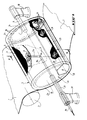
- an apparatus for drying a sheet material such as paper 1 essentially comprises a rotary cylinder 2 on which the material 1 is applied which can be guided by auxiliary rollers such that 3, as well as a fixed cylinder generally identified in 4 which is housed inside the rotary cylinder 2 and which mainly consists of a first cylindrical surface 5 and a second cylindrical surface 6 externally concentric to the first and defining therewith a chamber 7 for distributing the combustible gas.
- the pipe 9 In the first cylindrical surface 5 opens at 8 a pipe 9 for the arrival of the combustible gas. More specifically, the pipe 9 consists of a pipe portion 9b extending along the common axis of the rotary cylinder 2 and the fixed cylinder 4, and is connected to a pipe portion 9a extending radially and communicating with the distribution chamber 7 of the combustible gas which, to be precise, is a mixture of combustible gas and combustion air in a proportion close to the stoichiometry.
- FIGS. 1 and 2 a cap secured to the first cylindrical surface 5 and favoring the distribution of the combustible gas leaving at 8, in the distribution chamber 7.
- the rotary cylinder 2 is supported and driven in rotation by shafts 11 mounted in bearings 30. As it clearly appears in FIG. 1, one of these shafts 11 is axially crossed by the por tion 9b of the fuel gas supply line. In other words, one of the shafts 11 rotates around the pipe portion 9b, when the apparatus is in operation to allow the drying of the sheet of paper 1.
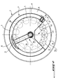
- the unitary and fixed cylinder 4, constituted by the two cylindrical surfaces 5 and 6 is provided with a recess 12 which is particularly clearly visible in FIG. 2.
- This recess 12 extends along a generatrix of the cylinder 4 and is for example constituted by a sheet having substantially the shape of a V in cross section and to the wings of which V are connected the concentric cylindrical surfaces 5 and 6.
- the recess 12 communicates with a window 13 formed in the second cylindrical surface 6, so as to open into an annular space 14 delimited by the second cylindrical surface 6 and the rotary cylinder 2.
- the recess 12 is closed at its ends by the flanges 15, 16 of the fixed cylinder 4.
- One 16 of these flanges has holes 17 only in its part opposite the recess 12.
- the rotary cylinder 2 also includes flanges identified respectively in 2a and 2b in FIG. 1.
- One 2b of these flanges has a plurality of openings 18 arranged in a crown and capable of coming opposite the orifices 17 during the rotation of the rotary cylinder 2 with respect to the fixed cylinder 4 formed by two cylindrical surfaces 5 and 6.
- the burnt gases circulating in the annular space 14 and passing through the recess 12 via the window 13 can be removed from the rotary cylinder 2.
- the window 13 can be obtained by a plate or the like 13a (FIG. 2) partially covering the open side of the V12-shaped recess.
- the second cylindrical surface 6 of the fixed cylinder 4 is made of a fibrous material which is refractory and porous, so that the combustible gas distributed in the chamber 7 can pass through said material.
- an ignition means forming a kind of candle capable of causing combustion.
- This means 19 is mounted on and protrudes from the second cylindrical surface 6, so that the combustible gas passing through said surface will be ignited, and the flame will especially catch on the outer periphery of this cylindrical surface.
- the cylindrical surface 6 will be brought to a very high temperature, close to 800 ° C., and thus the heat produced by the flame will radiate in the direction of the rotary cylinder 2, in the annular space 14.
- the combustible gas feeds the device through line 9, while the rotary cylinder 2 on which a sheet of paper 1 is applied, is rotated by any suitable means and not shown.
- This gas-air mixture leaving at 8 is distributed in a homogeneous manner, before combustion, in the chamber 7, and it crosses the cylindrical surface 6 which is made of a fibrous, porous and refractory material.
- the candle 19 causes the ignition of the gas mixture passing through the cylindrical surface 6, and the flame will thus hang over the entire outer periphery of said surface.
- the gases burned in the annular space 14 will be evacuated through the window 13, the recess 12, the orifices 17 and the openings 18 communicating with a system (not shown) external to the rotary cylinder 2 and allowing the evacuation of the fumes.
- the burnt gas evacuation system constituted by the window 13, the recess 12 and the orifices and openings 17 and 18 will favor, because of its design and its geometry, the acceleration of the speed of entry of the burnt gases into the recess 12 and therefore good circulation of these gases in the annular space 14. In other words, the burnt gases will be somehow sucked through the slot 13 to then circulate in the recess 12 before be discharged through the openings 17 and the openings 18.
- An apparatus for drying sheet materials has therefore been produced according to the invention which, because of its particular and simple design, makes it possible to obtain uniform and controllable temperatures around the periphery of the rotary cylinder, so as to thus allow drying. fast and efficient web materials.
- the rotary cylinder rotation drive system as well as the smoke evacuation system of this device can be any.
- the device can include any various insulating means, and the assembly of the constituent elements, namely in particular the assembly of the elements constituting the fixed cylinder inside the rotary cylinder, can also be any.
Landscapes
- Engineering & Computer Science (AREA)
- Chemical & Material Sciences (AREA)
- Combustion & Propulsion (AREA)
- Textile Engineering (AREA)
- Mechanical Engineering (AREA)
- General Engineering & Computer Science (AREA)
- Drying Of Solid Materials (AREA)
- Paper (AREA)
Abstract
Description
- La présente invention a essentiellement pour objet un appareil de séchage de matériaux en nappe tels que papier ou tissu par exemple.
- On a déjà proposé des appareils de séchage de matériaux en nappe comprenant essentiellement un cylindre rotatif sur lequel est appliqué le matériau à sécher et une source de chaleur exerçant une action de chauffage à l'intérieur du cylindre pour sécher ledit matériau.
- Ces appareils dans lesquels la source de chaleur pouvait être constituée par de la vapeur ou par un brûleur à gaz monté dans l'axe du cylindre rotatif, étaient généralement compliqués et, bien souvent, n'étaient pas satisfaisants sur le plan de la rapidité et de l'efficacité du séchage.
- Aussi, la présente invention a pour but de remédier notamment à ces inconvénients en proposant un appareil de séchage ayant une structure spéciale mais très simple et fonctionnant par rayonnement de la source de chaleur au voisinage immédiat du cylindre rotatif, de sorte que le séchage du matériau appliqué sur et entraîné par ce cylindre est soumis à un séchage particulièrement rapide et efficace.
- Acet effet, l'invention a pour objet un appareil de séchage de matériaux en nappe tels que papier par exemple et du type comprenant un cylindre rotatif sur lequel est appliqué le matériau à sécher, et une source de chaleur exerçant une action de chauffage à l'intérieur du cylindre pour sécher ledit matériau, caractérisé en ce que la source de chaleur est constituée par:
- - une première surface cylindrique fixe dans laquelle débouche une arrivée de gaz combustible,
- - une deuxième surface cylindrique fixe extérieurement concentrique à la première et définissant avec celle-ci une chambre de répartition du gaz combustible, et
- - au moins un moyen d'allumage du gaz combustible traversant ladite deuxième surface pour chauffer celle-ci à très haute température et produire de la chaleur rayonnant dans l'espace annulaire compris entre cette deuxième surface et le cylindre rotatif extérieurement concentrique à celle-ci.
- Suivant une autre caractéristique de cetappareil, la première et la deuxième surfaces cylindriques forment un cylindre unitaire fixe comportant un évidement s'étendant suivant une génératrice de ce cylindre et par lequel sont évacués les gaz brûlés circulant dans l'espace annulaire précité.
- Suivant un mode de réalisation préféré, l'évidement précité communique avec une fenêtre ménagée dans la deuxième surface cylindrique pour déboucher dans l'espace annulaire précité, et cet évidement est fermé à ses extrémités par les flasques du cylindre fixe précité, l'un de ces flasques comportant des orifices en regard de l'évidement.
- Selon encore une autre caractéristique de cet appareil, l'un des flasques du cylindre rotatif comporte une pluralité d'ouvertures agencées en couronne et susceptibles de venir en regard des orifices précitées pour permettre l'échappement des gaz brûlés.
- L'appareil de séchage selon cette invention est encore caractérisé par le fait que le cylindre rotatif est muni d'arbres montés à rotation dans des paliers, l'un des arbres étant axialement traversé par un conduit d'alimentation en gaz combustible raccordé à la première surface cylindrique précitée.
- Sur le cylindre unitaire fixe précité est monté un détecteur de flamme faisant saillie de la deuxième surface cylindrique et débouchant dans l'espace annulaire précité.
- La deuxième surface cylindrique est réalisé en un matériau fibreux réfractaire et poreux sur lequel s'accroche la flamme produite par le moyen d'allumage du gaz combustible traversant ladite surface.
- Mais d'autres caractéristiques et avantages de l'invention apparaîtront mieux dans la description détaillée qui suit et se réfère aux dessins annexés, donnés uniquement à titre d'exemple, et dans lesquels:
- La figure 1 est une vue très schématique et en perspective avec arrachements d'un appareil de séchage selon cette invention.
- La figure 2 est une vue en coupe suivant la ligne II-II de la figure 1.
- Comme on le voit bien sur les figures, un appareil de séchage d'un matériau en nappe tel que papier 1, selon cette invention, comprend essentiellement un cylindre rotatif 2 sur lequel est appliqué le matériau 1 qui peut être guidé par des rouleaux annexes tels que 3, ainsi qu'un cylindre fixe repéré d'une manière générale en 4 qui est logé à l'intérieur du cylindre rotatif 2 et qui se compose principalement d'une première surface cylindrique 5 et d'une deuxième surface cylindrique 6 extérieurement concentrique à la première et définissant avec celle-ci une chambre 7 de répartition du gaz combustible.
- Dans la première surface cylindrique 5 débouche en 8 une conduite 9 d'arrivée du gaz combustible. Plus précisément, la conduite 9 se compose d'une portion de conduite 9b s'étendant suivant l'axe commun du cylindre rotatif 2 et du cylindre fixe 4, et est reliée à une portion de conduite 9a s'étendant radialement et communiquant avec la chambre de répartition 7 du gaz combustible qui, pour être précis, est un mélange de gaz combustible et d'air comburant dans une proportion proche de la stoechiométrie.
- On a montré en 10 sur les figures 1 et 2 un chapeau solidaire de la première surface cylindrique 5 et favorisant la répartition du gaz combustible sortant en 8, dans la chambre de répartition 7.
- Le cylindre rotatif 2 est supporté et entraîné en rotation par des arbres 11 montés dans des paliers 30. Comme il apparaît clairement sur la figure 1, l'un de ces arbres 11 est axialement traversé par la portion 9b de conduite d'alimentation en gaz combustible. En d'autres termes, l'un des arbres 11 tourne autour de la portion de conduite 9b, lorsque l'appareil est en fonctionnement pour permettre le séchage de la nappe de papier 1.
- Le cylindre unitaire et fixe 4, constitué par les deux surfaces cylindriques 5 et 6 est pourvu d'un évidement 12 qui est particulièrement bien visible sur la figure 2. Cet évidement 12 s'étend suivant une génératrice du cylindre 4 et est par exemple constitué par une tôle présentant sensiblement la forme d'un V en section transversale et aux ailes duquel V sont raccordées les surfaces cylindriques concentriques 5 et 6.
- L'évidement 12 communique avec une fenêtre 13 ménagée dans la deuxième surface cylindrique 6, de façon à déboucher dans un espace annulaire 14 délimité par la deuxième surface cylindrique 6 et le cylindre rotatif 2.
- Comme on le voit sur la figure 1, l'évidement 12 est fermé à ses extrémités par les flasques 15, 16 du cylindre fixe 4. L'un 16 de ces flasques comporte des orifices 17 uniquement dans sa partie en regard de l'évidement 12.
- Le cylindre rotatif 2 comporte également des flasques repérés respectivement en 2a et 2b sur la figure 1. L'un 2b de ces flasques comporte une pluralité d'ouvertures 18 agencées en couronne et susceptibles de venir en regard des orifices 17 lors de la rotation du cylindre rotatif 2 par rapport au cylindre fixe 4 formé de deux surfaces cylindriques 5 et 6. Ainsi comme on l'expliquera en détail plus loin, les gaz brûlés circulant dans l'espace annulaire 14 et passant par l'évidement 12 via la fenêtre 13 pourront être évacués du cylindre rotatif 2.
- Suivant un mode de réalisation préféré, la fenêtre 13 pourra être obtenue par une plaque ou analogue 13a (figure 2) recouvrant partiellement le côté ouvert de l'évidement en forme de V12.
- La deuxième surface cylindrique 6 du cylindre fixe 4 est réalisée en un matériau fibreux qui est réfractaire et poreux, de sorte que le gaz combustible réparti dans la chambre 7 pourra traverser ledit matériau.
- On en montré en 19 sur la figure 1 un moyen d'allumage formant en quelque sorte une bougie susceptible d'engendrer la combustion. Ce moyen 19 est monté sur et fait saillie de la deuxième surface cylindrique 6, de sorte que le gaz combustible traversant ladite surface sera enflammé, et la flamme s'accrochera surtout le pourtour externe de cette surface cylindrique. En d'autres termes, la surface cylindrique 6 sera portée à une très haute température, voisine de 800°C, et ainsi la chaleur procurée par la flamme rayonnera en direction du cylindre rotatif 2, dans l'espace annulaire 14.
- On voit encore en 20 sur les figures 1 et 2, un détecteur de flamme solidaire du cylindre fixe 4 et faisant saillie de la deuxième surface cylindrique 6 pour déboucher dans l'espace annulaire 14.
- Mais pour une meilleure compréhension de l'invention, on expliquera brièvement ci-après le fonctionnement et les avantages de l'apparei de séchage décrit ci-dessus.
- Le gaz combustible, ou plutôt le mélange gaz-air alimente l'appareil par la conduite 9, alors que le cylindre rotatif 2 sur lequel est appliquée une nappe de papier 1, est entraîné en rotation par tout moyen approprié et non représenté.
- Ce mélange gaz-air sortant en 8 est réparti d'une façon homogène, avant combustion, dans la chambre 7, et il traverse la surface cylindrique 6 qui est en un matériau fibreux, poreux et réfractaire.
- La bougie 19 provoque l'allumage du mélange gazeux traversant la surface cylindrique 6, et la flamme va ainsi s'accrocher sur tout le pourtour extérieur de ladite surface.
- Par conséquent, la chaleur produite va rayonner dans l'espace annulaire 14 pour permettre un chauffage homogène et efficace de la paroi cylindrique constituant le cylindre rotatif 2, c'est-à-dire un séchage rapide et efficace de la nappe de papier 1.
- Les gaz brûlés dans l'espace annulaire 14 seront évacués par la fenêtre 13, l'évidement 12, les orifices 17 et les ouvertures 18 communiquant avec un système (non représenté) extérieur au cylindre rotatif 2 et permettant l'évacuation des fumées.
- On observera ici que le système d'évacuation des gaz brûlés constitué par la fenêtre 13, l'évidement 12 et les orifices et ouvertures 17 et 18 favorisera, du fait de sa conception et de sa géométrie, l'accélération de la vitesse d'entrée des gaz brûlés dans l'évidement 12 et donc une bonne circulation de ces gaz dans l'espace annulaire 14. Autrement dit, les gaz brûlés seront en quelque sorte aspirés par la fente 13 pour circuler ensuite dans l'évidement 12 avant d'être évacués par les orifices 17 et les ouvertures 18.
- On a donc réalisé suivant l'invention un appareil de séchage de matériaux en nappe qui, du fait de sa conception particulière et simple, permet d'obtenir des températures homogènes et contrôlables sur le pourtour du cylindre rotatif, de façon à permettre ainsi un séchage rapide et efficace des matériaux en nappe.
- Bien entendu, l'invention n'est nullement limitée au mode de réalisation décrit et illustré qui n'a été donné qu'à titre d'exemple.
- C'est ainsi que le système d'entraînement en rotation du cylindre rotatif, de même que le système d'évacuation des fumées de cet appareil peuvent être quelconques.Egalement, l'appareil peut comporter divers moyens isolants quelconques, et l'assemblage des éléments le constituant, à savoir notamment l'assemblage des éléments constituant le cylindre fixe à l'intérieur du cylindre rotatif, peut aussi être quelconque.
- C'est dire que l'invention comprend tous les équivalents techniques des moyens décrits ainsi que leurs combinaisons si celles-ci sont effectuées suivant son esprit.
Claims (5)
Applications Claiming Priority (2)
| Application Number | Priority Date | Filing Date | Title |
|---|---|---|---|
| FR9215851 | 1992-12-29 | ||
| FR9215851A FR2699993B1 (fr) | 1992-12-29 | 1992-12-29 | Appareil de séchage de matériaux en nappe tels que du papier par exemple. |
Publications (2)
| Publication Number | Publication Date |
|---|---|
| EP0607720A1 true EP0607720A1 (fr) | 1994-07-27 |
| EP0607720B1 EP0607720B1 (fr) | 1997-02-12 |
Family
ID=9437222
Family Applications (1)
| Application Number | Title | Priority Date | Filing Date |
|---|---|---|---|
| EP19930403084 Expired - Lifetime EP0607720B1 (fr) | 1992-12-29 | 1993-12-17 | Appareil de séchage de matériaux en nappe tels que du papier par exemple |
Country Status (4)
| Country | Link |
|---|---|
| EP (1) | EP0607720B1 (fr) |
| CA (1) | CA2112034A1 (fr) |
| DE (1) | DE69308122T2 (fr) |
| FR (1) | FR2699993B1 (fr) |
Cited By (2)
| Publication number | Priority date | Publication date | Assignee | Title |
|---|---|---|---|---|
| EP0708301A1 (fr) * | 1994-10-18 | 1996-04-24 | Gastec N.V. | Dispositif de séchage à combustion alimenté par un gaz |
| CN103712432A (zh) * | 2012-10-09 | 2014-04-09 | 广州市蓝炬燃烧设备有限公司 | 采用燃气红外线燃烧器的转鼓干燥器 |
Families Citing this family (7)
| Publication number | Priority date | Publication date | Assignee | Title |
|---|---|---|---|---|
| US5553391A (en) * | 1995-06-05 | 1996-09-10 | Bakalar; Sharon F. | Method and apparatus for heat treating webs |
| US5791065A (en) * | 1997-02-06 | 1998-08-11 | Asea Brown Boveri, Inc. | Gas heated paper dryer |
| DE19901145A1 (de) * | 1999-01-14 | 2000-07-20 | Krieger Gmbh & Co Kg | Als Flächenstrahler ausgebildeter Infrarot-Strahler |
| DE102004006514A1 (de) * | 2004-02-10 | 2005-08-25 | Voith Paper Patent Gmbh | Verfahren zur Beheizung einer Walze sowie beheizbare Walze |
| DE102006013445A1 (de) * | 2006-03-17 | 2007-09-20 | Gvp Gesellschaft Zur Vermarktung Der Porenbrennertechnik Mbh | Walze mit Heizvorrichtung |
| AT516855B1 (de) * | 2015-02-17 | 2016-09-15 | Georg Michael Dipl Ing Dr Techn Ickinger | Luftbeheizter Trockenzylinder Verwendung, Verfahren, Vorrichtung |
| CN105444556B (zh) * | 2015-12-25 | 2018-04-13 | 广东华凯科技股份有限公司 | 一种直燃式燃气烘缸 |
Citations (6)
| Publication number | Priority date | Publication date | Assignee | Title |
|---|---|---|---|---|
| US2984472A (en) * | 1957-07-19 | 1961-05-16 | Ind Heat Engineering Company | Drying machine |
| US3271016A (en) * | 1964-10-27 | 1966-09-06 | Ind Heat Engineering Corp | Machine for heat setting synthetic fabrics |
| FR1544407A (fr) * | 1966-11-15 | 1968-10-31 | Procédé pour le chauffage et le séchage indirects de bandes de textile ou de papier et d'autres matières, et dispositif pour la mise en oeuvre du dit procédé | |
| CH574010A5 (fr) * | 1975-08-14 | 1976-02-15 | Kramlehner Karl | |
| US4688335A (en) * | 1986-02-18 | 1987-08-25 | James River Corporation Of Nevada | Apparatus and method for drying fibrous web material |
| US4693015A (en) * | 1985-08-26 | 1987-09-15 | Hercules Incorporated | Direct fired cylinder dryer |
-
1992
- 1992-12-29 FR FR9215851A patent/FR2699993B1/fr not_active Expired - Fee Related
-
1993
- 1993-12-17 EP EP19930403084 patent/EP0607720B1/fr not_active Expired - Lifetime
- 1993-12-17 DE DE1993608122 patent/DE69308122T2/de not_active Expired - Fee Related
- 1993-12-21 CA CA002112034A patent/CA2112034A1/fr not_active Abandoned
Patent Citations (6)
| Publication number | Priority date | Publication date | Assignee | Title |
|---|---|---|---|---|
| US2984472A (en) * | 1957-07-19 | 1961-05-16 | Ind Heat Engineering Company | Drying machine |
| US3271016A (en) * | 1964-10-27 | 1966-09-06 | Ind Heat Engineering Corp | Machine for heat setting synthetic fabrics |
| FR1544407A (fr) * | 1966-11-15 | 1968-10-31 | Procédé pour le chauffage et le séchage indirects de bandes de textile ou de papier et d'autres matières, et dispositif pour la mise en oeuvre du dit procédé | |
| CH574010A5 (fr) * | 1975-08-14 | 1976-02-15 | Kramlehner Karl | |
| US4693015A (en) * | 1985-08-26 | 1987-09-15 | Hercules Incorporated | Direct fired cylinder dryer |
| US4688335A (en) * | 1986-02-18 | 1987-08-25 | James River Corporation Of Nevada | Apparatus and method for drying fibrous web material |
Cited By (3)
| Publication number | Priority date | Publication date | Assignee | Title |
|---|---|---|---|---|
| EP0708301A1 (fr) * | 1994-10-18 | 1996-04-24 | Gastec N.V. | Dispositif de séchage à combustion alimenté par un gaz |
| NL9401723A (nl) * | 1994-10-18 | 1996-06-03 | Gastec Nv | Gasgestookte drooginrichting. |
| CN103712432A (zh) * | 2012-10-09 | 2014-04-09 | 广州市蓝炬燃烧设备有限公司 | 采用燃气红外线燃烧器的转鼓干燥器 |
Also Published As
| Publication number | Publication date |
|---|---|
| EP0607720B1 (fr) | 1997-02-12 |
| CA2112034A1 (fr) | 1994-06-30 |
| DE69308122T2 (de) | 1997-09-25 |
| FR2699993A1 (fr) | 1994-07-01 |
| FR2699993B1 (fr) | 1995-02-24 |
| DE69308122D1 (de) | 1997-03-27 |
Similar Documents
| Publication | Publication Date | Title |
|---|---|---|
| EP2404112B1 (fr) | Porte à brûleur intégré pour appareil de chauffage | |
| EP0607720B1 (fr) | Appareil de séchage de matériaux en nappe tels que du papier par exemple | |
| BE897285A (fr) | Bruleur d'huile du type a pot | |
| FR2503851A1 (fr) | Appareil de sechage uniforme en epaisseur de bandes poreuses humides | |
| FR2678360A1 (fr) | Appareil de chauffage avec bruleur catalytique. | |
| EP0313479B1 (fr) | Appareil chauffant avec brûleur catalytique | |
| FR2791416A1 (fr) | Dispositif de combustion catalytique emettant un rayonnement infra-rouge | |
| CA2237843C (fr) | Systeme de rechauffe dichotomique reduisant les pertes en sec | |
| FR2597578A1 (fr) | Appareil a bruleur, notamment chauffe-eau, muni d'une soufflante | |
| FR2780489A1 (fr) | Perfectionnement aux bruleurs comportant au moins trois conduits d'alimentation en air, dont deux axial et en rotation, concentriques avec au moins une alimentation-en combustible, et un stabilisateur central | |
| FR2731065A1 (fr) | Dispositif de cuisson | |
| EP0998648B1 (fr) | Appareil de chauffage | |
| FR2710726A1 (fr) | Brûleur radiant à gaz pour cuisinière ou table de cuisson. | |
| EP0768462B1 (fr) | Diffuseur annulaire de recyclage de gaz carburés, pour moteur à combustion interne | |
| FR2654806A1 (fr) | Appareil de chauffage au gaz par rayonnement infrarouge. | |
| EP0026150B1 (fr) | Appareil de chauffage à combustibles solides, pouvant également brûler des combustibles liquides | |
| FR2541430A1 (fr) | Dispositif de chauffage au mazout, au gaz, ou au bois, ou autre combustible solide | |
| FR2472719A1 (fr) | Bruleur a gazeification pour carburant liquide | |
| FR2763670A1 (fr) | Appareil de chauffage au gaz, notamment pour les batiments d'elevage | |
| FR2678356A1 (fr) | Bruleur catalytique a air induit. | |
| BE520000A (fr) | ||
| CH629570A5 (en) | Two-stroke engine and method for activating this engine | |
| FR2758575A1 (fr) | Installation de sechage d'une bande de papier | |
| FR2560355A1 (fr) | Bruleur a vaporisation pour chauffage de vehicules automobiles | |
| FR2680225A1 (fr) | Dispositifs de chauffage au gaz par rayonnement. |
Legal Events
| Date | Code | Title | Description |
|---|---|---|---|
| PUAI | Public reference made under article 153(3) epc to a published international application that has entered the european phase |
Free format text: ORIGINAL CODE: 0009012 |
|
| AK | Designated contracting states |
Kind code of ref document: A1 Designated state(s): DE GB SE |
|
| 17P | Request for examination filed |
Effective date: 19940921 |
|
| 17Q | First examination report despatched |
Effective date: 19950925 |
|
| GRAG | Despatch of communication of intention to grant |
Free format text: ORIGINAL CODE: EPIDOS AGRA |
|
| GRAH | Despatch of communication of intention to grant a patent |
Free format text: ORIGINAL CODE: EPIDOS IGRA |
|
| GRAH | Despatch of communication of intention to grant a patent |
Free format text: ORIGINAL CODE: EPIDOS IGRA |
|
| GRAA | (expected) grant |
Free format text: ORIGINAL CODE: 0009210 |
|
| AK | Designated contracting states |
Kind code of ref document: B1 Designated state(s): DE GB SE |
|
| REF | Corresponds to: |
Ref document number: 69308122 Country of ref document: DE Date of ref document: 19970327 |
|
| GBT | Gb: translation of ep patent filed (gb section 77(6)(a)/1977) |
Effective date: 19970515 |
|
| PGFP | Annual fee paid to national office [announced via postgrant information from national office to epo] |
Ref country code: GB Payment date: 19971208 Year of fee payment: 5 |
|
| PGFP | Annual fee paid to national office [announced via postgrant information from national office to epo] |
Ref country code: SE Payment date: 19971218 Year of fee payment: 5 |
|
| PLBE | No opposition filed within time limit |
Free format text: ORIGINAL CODE: 0009261 |
|
| STAA | Information on the status of an ep patent application or granted ep patent |
Free format text: STATUS: NO OPPOSITION FILED WITHIN TIME LIMIT |
|
| PGFP | Annual fee paid to national office [announced via postgrant information from national office to epo] |
Ref country code: DE Payment date: 19971230 Year of fee payment: 5 |
|
| 26N | No opposition filed | ||
| PG25 | Lapsed in a contracting state [announced via postgrant information from national office to epo] |
Ref country code: GB Free format text: LAPSE BECAUSE OF NON-PAYMENT OF DUE FEES Effective date: 19981217 |
|
| PG25 | Lapsed in a contracting state [announced via postgrant information from national office to epo] |
Ref country code: SE Free format text: LAPSE BECAUSE OF NON-PAYMENT OF DUE FEES Effective date: 19981218 |
|
| GBPC | Gb: european patent ceased through non-payment of renewal fee |
Effective date: 19981217 |
|
| PG25 | Lapsed in a contracting state [announced via postgrant information from national office to epo] |
Ref country code: DE Free format text: LAPSE BECAUSE OF NON-PAYMENT OF DUE FEES Effective date: 19991001 |