EP0608427A1 - Amortisseur - Google Patents
Amortisseur Download PDFInfo
- Publication number
- EP0608427A1 EP0608427A1 EP92922601A EP92922601A EP0608427A1 EP 0608427 A1 EP0608427 A1 EP 0608427A1 EP 92922601 A EP92922601 A EP 92922601A EP 92922601 A EP92922601 A EP 92922601A EP 0608427 A1 EP0608427 A1 EP 0608427A1
- Authority
- EP
- European Patent Office
- Prior art keywords
- main
- valve
- chamber
- pilot
- pressure
- Prior art date
- Legal status (The legal status is an assumption and is not a legal conclusion. Google has not performed a legal analysis and makes no representation as to the accuracy of the status listed.)
- Granted
Links
- 239000006096 absorbing agent Substances 0.000 title claims abstract description 19
- 230000035939 shock Effects 0.000 title claims description 17
- 238000013016 damping Methods 0.000 abstract description 13
- 238000006073 displacement reaction Methods 0.000 abstract 2
- 230000004044 response Effects 0.000 description 12
- 238000010276 construction Methods 0.000 description 10
- 230000008859 change Effects 0.000 description 4
- 230000003247 decreasing effect Effects 0.000 description 4
- 230000000630 rising effect Effects 0.000 description 4
- 230000009471 action Effects 0.000 description 3
- 230000003111 delayed effect Effects 0.000 description 3
- 230000000694 effects Effects 0.000 description 3
- 230000002093 peripheral effect Effects 0.000 description 3
- 230000006835 compression Effects 0.000 description 1
- 238000007906 compression Methods 0.000 description 1
- 239000012530 fluid Substances 0.000 description 1
- 230000006872 improvement Effects 0.000 description 1
- 230000009467 reduction Effects 0.000 description 1
Images



Classifications
-
- F—MECHANICAL ENGINEERING; LIGHTING; HEATING; WEAPONS; BLASTING
- F16—ENGINEERING ELEMENTS AND UNITS; GENERAL MEASURES FOR PRODUCING AND MAINTAINING EFFECTIVE FUNCTIONING OF MACHINES OR INSTALLATIONS; THERMAL INSULATION IN GENERAL
- F16F—SPRINGS; SHOCK-ABSORBERS; MEANS FOR DAMPING VIBRATION
- F16F9/00—Springs, vibration-dampers, shock-absorbers, or similarly-constructed movement-dampers using a fluid or the equivalent as damping medium
- F16F9/32—Details
- F16F9/44—Means on or in the damper for manual or non-automatic adjustment; such means combined with temperature correction
- F16F9/46—Means on or in the damper for manual or non-automatic adjustment; such means combined with temperature correction allowing control from a distance, i.e. location of means for control input being remote from site of valves, e.g. on damper external wall
- F16F9/465—Means on or in the damper for manual or non-automatic adjustment; such means combined with temperature correction allowing control from a distance, i.e. location of means for control input being remote from site of valves, e.g. on damper external wall using servo control, the servo pressure being created by the flow of damping fluid, e.g. controlling pressure in a chamber downstream of a pilot passage
-
- B—PERFORMING OPERATIONS; TRANSPORTING
- B60—VEHICLES IN GENERAL
- B60G—VEHICLE SUSPENSION ARRANGEMENTS
- B60G2500/00—Indexing codes relating to the regulated action or device
- B60G2500/10—Damping action or damper
-
- B—PERFORMING OPERATIONS; TRANSPORTING
- B60—VEHICLES IN GENERAL
- B60G—VEHICLE SUSPENSION ARRANGEMENTS
- B60G2500/00—Indexing codes relating to the regulated action or device
- B60G2500/10—Damping action or damper
- B60G2500/11—Damping valves
-
- B—PERFORMING OPERATIONS; TRANSPORTING
- B60—VEHICLES IN GENERAL
- B60G—VEHICLE SUSPENSION ARRANGEMENTS
- B60G2600/00—Indexing codes relating to particular elements, systems or processes used on suspension systems or suspension control systems
- B60G2600/22—Magnetic elements
- B60G2600/26—Electromagnets; Solenoids
-
- F—MECHANICAL ENGINEERING; LIGHTING; HEATING; WEAPONS; BLASTING
- F16—ENGINEERING ELEMENTS AND UNITS; GENERAL MEASURES FOR PRODUCING AND MAINTAINING EFFECTIVE FUNCTIONING OF MACHINES OR INSTALLATIONS; THERMAL INSULATION IN GENERAL
- F16F—SPRINGS; SHOCK-ABSORBERS; MEANS FOR DAMPING VIBRATION
- F16F2230/00—Purpose; Design features
- F16F2230/24—Detecting or preventing malfunction, e.g. fail safe
Definitions
- the present invention relates to a shock absorber by which the damping power thereof is controlled by the electric current for energizing the linear solenoid.
- the damping power thereof is freely varied depending on the cruising conditions.
- a system has been made known to the public, wherein the amount and rate of expansion or compression are detected so that the pressure for actuating a main valve, which is provided in the piston for opening and closing the oil passage, is freely varied by controlling energization of the linear solenoid continuously or discontinuously during each stroke of the piston (for example, by Unexamined Japanese Patent Publication No. 261528/1989 (corresponding to United States Patent No. 5,090,525 and European Patent Publication No. 0330634A)).
- the shock absorber used therein has the construction as shown in the schematic principle in Fig. 7.
- the shock absorber comprises a piston 16 for defining two main oil chambers 12, 14 in a cylinder 10, a main valve 22 provided in the piston 16 for defining a main chamber 18 and a pilot chamber 20, and an orifice 24 interposed between these main and pilot chambers 18, 20.
- the hydraulic pressure in the high pressure side main oil chamber 12 or 14 is transmitted to the main chamber 18.
- said main valve 22 is moved to open a main oil channel 28 (28a, 28b), which communicates with the two main oil chambers 12, 14, so as to control the damping power.
- the interior side of the main oil channel 28a is defined to be annular to surround the outer periphery of the main valve 22.
- the pressure in the high pressure side main oil chamber 12 or 14 is transmitted through the main chamber 18 and the orifice 24 to the pilot chamber 20. And, when the pressure in this pilot chamber 20 (Pilot Chamber Pressure P p ) exceeds the set thrusting power P s of the linear solenoid 26, a pilot valve 30 is opened. Then, under the action of pressure drop upon passage of fluid medium through the such orifice 24 and opening of the pilot valve 30, the pilot chamber pressure P p at the downstream of the orifice 24 becomes lower than the pressure in the main chamber 18 (Main Chamber Pressure P m ). Thus caused pressure difference (P m - P p ) urges the main valve 22 to move upwards.
- Reference numeral 31 designates a spring to restore the main valve 22.
- a valve shaft 32 is provided integrally with the plunger of the solenoid 26 on the pilot valve 30 so that the valve shaft 32 extends through the pilot chamber 20 and the main valve 22 to be faced or exposed to the main chamber 18.
- the main valve 22 is endowed with a restoring force to close the main oil channel 28 by the action of a spring 31.
- the pressure in the high pressure side main oil chamber 12 or 14 acts from the main chamber 18 to the bottom end face 32A of the valve shaft 32 directly.
- the response speed of the main valve 22 responsive to the change in set thrusting power of the linear solenoid 26 can be increased as compared to the construction shown in the preceding Figure 7.
- the oil flow from the main chamber 18 to the pilot chamber 20 is blocked, so that restoration of the main valve 22 is retarded to result in poor response property at the restoring step.
- the present invention has been accomplished in view of the circumstances as aforementioned, and the object thereof is to provide a shock absorber by which the response property of the main valve responsive to change in movement of the piston or change in set thrusting power of the linear solenoid is improved.
- a shock absorber characterised by comprising a piston for defining two main oil chambers in a cylinder, a main oil channel for communicating said two main oil chambers, a main valve for opening and closing the main oil channel, a main chamber facing to one end of the main valve so as to transmit the hydraulic pressure in the high pressure side main oil chamber for biasing said main valve toward the direction for opening said main oil channel, a pilot chamber facing to the other end of said main valve, a pilot valve for receiving the pressure in the main chamber to be opened to release the pressure in said pilot chamber to the low pressure side main oil chamber, a linear solenoid for biasing the pilot valve toward the closing direction, a variable orifice having a variable opening area varied by the relative movement of said pilot and main valves, and a pilot flow channel extending from said main chamber through the variable orifice and through the pilot valve to the low pressure side main oil chamber.
- a valve shaft extending through the main valve to have one end facing to the main chamber and biased by the linear solenoid may be provided so that a variable orifice is formed by a passage provided through the valve shaft and the main valve.
- a fixed orifice may be provided additionally in this passage.
- the main chamber, to which the one end of the main valve is faced, may be an isolated chamber to which the pressure in the high pressure side main oil chamber is transmitted through a one-way valve.
- the main valve may have one end provided with an annular stepped portion and an end face directly facing to one of the main oil chambers while the pressure in the other main oil chamber is transmitted to the stepped portion. In such a case, it is desirous that the pressure-bearing areas of the stepped portion and the end face should be differentiated from each other.
- a main pressure chamber may be formed in a cylidrical body which extends through the main valve, so that a variable orifice is provided by a pin, which extends from the such main pressure chamber through the pilot chamber to abut against the valve body, and the cylindrical body.
- Fig. 1 is a view showing the principle of a first embodiment
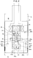
- Fig. 2 is a view showing the principle of a second embodiment
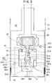
- Fig. 3 is a view showing the principle of a third embodiment
- Fig. 4 is a sectional view of the preceding embodiment
- Fig. 5 is a view showing the principle of a fourth embodiment
- Fig. 6 is a view showing the principle of a fifth embodiment
- Fig. 7 is a view showing the principle of the prior art device
- Fig. 8 is a view showing the principle of a device which has been proposed and improved by the inventor of this invention.
- a valve shaft 32 formed integrally with the plunger of a solenoid 26 is provided with a passage 34 which is elongated along the axial direction.
- the lower end of the passage 34 is opened on the outer periphery of the valve shaft 32 to form a variable orifice 36 in cooperation with an opening provided on the side of the main valve 22.
- the variable orifice 36 has an opening area which is decreased upon rising of the valve shaft 32 or upon lowering of the main valve 22.
- the top end of the passage 34 is opened to the pilot chamber 20.
- variable orifice 36 The opening area of the variable orifice 36 is set to have a predetermined area in the condition as shown in the Figure where the valve shaft 32 closes the pilot valve 30 and the main valve 22 closes the main oil channel 28.
- a pilot flow channel 38 (38a to 38d) is shown by the broken line, and one-way valves 40 (40a to 40d) are interposed respectively on the flow channels 38a to 38d.
- the valve shaft 32 is moved to the position at which the thrusting force P s of the solenoid and the main chamber pressure P m are balanced, and the main valve 22 is moved followingly.
- the main valve 22 is moved to broaden the variable orifice 36, the pressure difference is decreased to restrict the movement of the main valve 22. Since the varialbe orifice 36 has been thus broadened, transit of the oil from the main chamber 18 to the pilot chamber 20 is carried out smoothly to effect restoration of the valve 22 rapidly under the action of the spring 31. Accordingly, the response properties of the main valve 22 at the rising and restoring steps are improved. Similar operation sequence proceeds when a force in the expanding direction (the direction shown by the arrow E) is applied to the piston 16.
- Fig. 2 is a view showing the principle of a second embodiment.
- This embodiment has a fixed orifice 24A added to the passage 34 of the embodiment of Fig. 1.
- the passage 34A provided in the valve shaft 32 is shortened and the passage 34A becomes communicated with the pilot chamber 20 through a fixed orifice 24A.
- the pressure difference is immediately decreased as the variable orifice 36 is broadened so that the main valve 22 cannot be moved further. Accordingly, the position of the main valve 22 is limited by the stroke (stroke distance) of the valve shaft 32 of the pilot system, so that the stroke of the valve shaft 32 cannot take so large range inherently, leading the result that the stroke of the main valve cannot be set to a large value. Accordingly, there is a problem that the adjustable range of the damping power cannot be set in a so large range.
- the embodiment of Fig. 2 is to solve this problem.
- the pressure difference is rapidly incresed by means of a variable orifice 36A to improve the response property of the main valve 22 at the rising step, and on the other hand, the pressure difference between the pilot pressure P p and the main chamber pressure P m is lasted.
- a variable orifice 36A is closed and the pilot valve 30 is opened to decrease the pilot pressure P p rapidly.
- the main valve 22 is raised rapidly to open the main channel, so that the main valve 22 is raised at high speed.
- the response property of the main valve 22 is improved.
- the main valve 22 is kept moving upwards.
- the stroke of the main valve 22 is thus increased.
- the flow rate of oil flowing between both main oil chambers can be increased, whereby even a small damping power can be generated.
- the adjustable range thereof covers a larger range from a large damping power to a small damping power.
- Fig. 3 is a view showing the principle of a third embodiment.
- This embodiment comprises a main chamber facing to one end of the main valve 22A and having two partitioned portions 18A and 18B, the pressure-bearing areas of respective portions 18A, 18B are differentiated from each other.
- an annular stepped portion is formed on the outer periphery of the lower portion of the main valve 22A, the stepped portion being faced to one of the main chambers 18B, and the bottom end face of the main valve 22A is faced to the other main chamber 18A.
- the pressure for opening the pilot valve 30 relative to the compressing and expanding directions of the piston 16 can be controlled.
- the pressures in the main chambers 18A, 18B are transmitted through one-way valves 40a, 40c to a main pressure chamber 18C to act on the bottom end face 32B of the valve shaft 32 which faces to the main pressure chamber 18C.
- the driving thrust power required for the linear solenoid 26 can be set to a lower degree, whereby it is realized to speed-up the operation, compactmization of the solenoid 26 and saving of the driving electric current.
- Fig. 4 is a sectional view showing a practical construction example based on the third embodiment.
- the main chamber is partitioned into two portions 18A, 18B, and one of the main chamber 18A serves also as the main oil chamber 14.
- the valve body 30A of the pilot valve 30 is biased downwards by the plunger of the solenoid 26, and a valve plate 30B serving as the valve seat has a disk shape and is held loosely over the whole peripheral side thereof in the radial direction to be movable. By the movement of the valve plate 30B, irrelevant engagement of the valve seat caused by inalignment between the valve body 30A and the axis is dissolved.
- the main valve 22B is formed to have a cylinder having a bottom and having an opening which opens to the pilot chamber 20A.
- a guide cylinder 50 for the coil spring 31A is slidingly engaged with the interior pheriphery of the main valve 22B and a damper chamber 51 is formed and surrounds the outer periphery of the guide cylinder 50.
- An orifice 50a for communicating the pilot chamber 20A with the damper chamber 51 is provided through the guide cylinder 50.
- a slight gap is left between the outer periphery of the guide cylinder 50 and the sliding surface of the main valve 22B. Vibration of the main valve 22B is suppressed by the resistance of flowing oil flowing, through the orifice 50a and the aforementioned gap, between the damper chamber 51 and the pilot chamber 20A.
- the piston 16 is formed of a piston case 16A having an open lower end, a solenoid body 16B and a valve body 16C fitted in the piston case 16A in the described order from the bottom.
- the solenoid body 16B contains therein the linear solenoid 26, and has plural pilot flow channels 38b which extend radially from the pilot valve 30.
- Each of these pilot flow channels 38b has an outer peripheral end at which a ball-charge room 16Ba is formed to expand the outer pheripheral direction, and a ball for forming a one-way valve 40b is charged into the ball-charge room 16Ba.
- the open end edge 16Bb of the ball-charge room 16Ba is caulked to be inclined slightly bent towards the ball in order to prevent fall-out of the ball to facilitate assembly of the piston 16.
- the one-way valve 40b is opened when the upper main oil chamber 12 is in the low pressure side, and at that time the ball abuts against the interior surface of the piston case 16A.
- the main valve 22B is mounted in the valve body 16C from the side facing to the solenoid body 16B, and an annular groove 16Ca surrounding the main valve 22B is formed on the face of the valve body 16C facing to the solenoid 16B.
- This annular groove 16Ca is communicated with the lower main oil chamber 14 through a proper number of pilot flow channels 38d extending through the axial direction.
- the annular groove 16Ca is also communicated with the pilot flow channels 38b located in the solenoid body 16B through a proper number of flow channels 16Bc.
- a one-way valve 40d is formed by an annular plate valve mounted on this annular groove 16Ca.
- the one-way valve 40d is opened when the lower main oil chamber 14 is in the lower pressure side, and at that time the plate valve engages with the stepped portion of the annular groove 16Ca formed on the interior peripheral surface of the groove so that oil flows over the outer periphery of the plate valve.
- a cylidrical body 52 is screw-fitted to the main valve 22B from the side of the lower oil chamber 14, and the cylindrical body 52 is fixed by a lock member 53 which is further screwed into the main valve 22B from the downside.
- the fore end (top end) of the cylindrical body 52 extends into the pilot chamber 20A.
- a main pressure chamber 18C is defined in the cylindrical body 52. The pressure in the upper main oil chamber 12 is transmitted through a one-way valve 40c and the pressure in the lower main oil chamber 14 is transmitted through a bevelled one-way valve 40a to the main pressure chamber 18C.
- the top end portion of the cylindrical body 52 is converged towards the interior diametral direction to form a converged portion 52A to which an upwardly-extending pin 54, which projects from the interior of the cylindrical body 52, is engaged from the downside.
- This pin 54 has a lower portion forming a cylinder 54C slidable within the cylindrical body 52 and has a conical upper portion, from the top of which a pin portion 54B extends upwards. This conical portion opposes to the top end converged portion 52A of the cylindrical body 52 from the downside.
- a window 54A communicating through the interior of the cylinder 54C to the main pressure chamber 18C is provided at the vicinity of the outer periphery of the conical portion, so that oil can be flown from the main pressure chamber 18C to the pilot chamber 20A through this window 54A.
- the fixed position of the cylindrical body 52 is determined so that the pin portion 54B of the pin 54 abuts against the lower face of the valve body 30A of the pilot valve 30 under the condition such that the conical portion forms a variable orifice having an appropriate opening area is defined with the converged portion 52A of the cylindrical body 52.
- variable orifice becomes enlarged by the rising of the main valve 22
- the pressure difference is kept unchanged since there is a fixed orifice which is formed at the gap between the pin portion 54B and the converged portion 52A at the top of the clyndrical body 52. Accordingly, the stroke of the main valve relative to the moving distance of the pilot valve 30 is increased.
- the main valve 22B extends from the opening of the main chamber 18B to the main oil chamber 14.
- Four pawls 22Ba provided on the main valve 22B to extending in the radial direction engage with the open edge of the main chamber 18B from the side of the main chamber 18B.
- only the pawls 22Ba engage with the opening edgflow e of the side of the main chamber 18B to close the main channel. Accordingly, even if the gap is under a reduced pressure by the sqeezing effect of the oil flowing through the gap, the force for attracting the main valve 22B to the side toward the main oil chamber 14 is enfeebled.
- the interior bottom face of the main chamber 18B is formed of a smooth conical face 18Ba.
- the outer periphery 22Bb of the main valve 22B extending towards the main oil chamber 14 is formed to be smoothly contiguous with the conical face 18Ba to smoothen the oil flow.
- Fig. 5 is a view showing the principle of a fourth embodiment.
- This embodiment is an improvement of the embodiment of Fig. 1.
- an annular stepped portion is formed, similar to the embodiment as shown in Fig. 3, on the end of the main valve 22A at the side of the main chambers 18A, 18B.
- This stepped portion is faced to one main chamber 18B, and the lower end face of the main valve 22A is faced to the other main chamber 18A. Since the portions or parts other than that described just above is the same as those shown in Fig. 1, the description thereof will not be repeated.
- the pressure-bearing areas S1, S2 of the lower end face of the main valve 22A and the stepped portion are differentiated to set the pressures for opening the pilot valve 30 in the compressing direction and the expanding direction can be independently set.
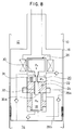
- Fig. 6 is a view showing the principle of a fifth embodiment.
- the biasing direction of the linear solenoid 26 is reversed to that in the embodiment of Fig. 3.
- the linear solenoid 26 biases the valve shaft 32 in the direction to close the pilot valve 30.
- a linear solenoid 26A of the embodiment of Fig. 6 biases the valve shaft 32 in the direction to close the pilot valve 30 by means of a spring 26B, and the linear solenoid 26A attracts the valve shaft 32 in the direction to open the pilot valve 30 upon energization thereof.
- the spring 26B urges the pilot valve 30 in the closing direction, and stable equiribrium is established at the position at which the force of this spring is balanced with the force of the main chamber pressure P m pushing the end face of the valve shaft 32.
- the main valve 22 is held at the position at which the pushing force of the main chamber pressure P m is balanced with the pushing force of the pilot chamber pressure P p . Accordingly, when a failure occurs in the electric circuit during cruising of the vehicle, this shock absorber is held to exert a damping power which is balanced with the spring force of the spring 26B to make it possible to allow cruising under such condition.
- variable orifice (36) having an opening area varied by the relative movement of a pilot valve (30) and a main valve (22) is provided in this invention, the operation speed of the main valve (22) can be increased to improve the response property.
- variable orifice (36) may be provided by a passage (34) formed in the valve shaft (32).
- the main chamber (18) may have a construction to transmit the pressure in the high pressure side main oil chamber (12 or 14) through the one-way valves (40a, 40c).
- the damping power may be variably set at the expanding and the compressing directions.
- the end face of the main valve may be faced directly to one of the main oil chamber.
- a cylindrical body (52) may be inserted through the main valve (22B) while forming a main pressure chamber 18C therein by the provision of a pin (54) extending from the main pressure 18C to abut against the valve body 30A of the pilot valve 30, whereby a variable orifice is formed by the pin (54) and the cylindrical body (52).
- the shock absorber of the present invention when used on a vehicle such as an automobile, motor bicycles or like, can control independently the damping power at the commpression side and the expansion side depending on the crusing condition, and additionally the damping power can be controlled intermediately of the storoke. Accordingly, the cruising performance of the vehicle can be improved to provide more comfortable feeling to the driver or the rider.
Landscapes
- Engineering & Computer Science (AREA)
- General Engineering & Computer Science (AREA)
- Mechanical Engineering (AREA)
- Fluid-Damping Devices (AREA)
Abstract
Applications Claiming Priority (3)
| Application Number | Priority Date | Filing Date | Title |
|---|---|---|---|
| JP30388091 | 1991-10-24 | ||
| JP303880/91 | 1991-10-24 | ||
| PCT/JP1992/001383 WO1993008416A1 (fr) | 1991-10-24 | 1992-10-23 | Amortisseur |
Publications (3)
| Publication Number | Publication Date |
|---|---|
| EP0608427A1 true EP0608427A1 (fr) | 1994-08-03 |
| EP0608427A4 EP0608427A4 (fr) | 1995-05-03 |
| EP0608427B1 EP0608427B1 (fr) | 1998-01-21 |
Family
ID=17926388
Family Applications (1)
| Application Number | Title | Priority Date | Filing Date |
|---|---|---|---|
| EP92922601A Expired - Lifetime EP0608427B1 (fr) | 1991-10-24 | 1992-10-23 | Amortisseur |
Country Status (4)
| Country | Link |
|---|---|
| US (1) | US5501307A (fr) |
| EP (1) | EP0608427B1 (fr) |
| DE (1) | DE69224200T2 (fr) |
| WO (1) | WO1993008416A1 (fr) |
Cited By (9)
| Publication number | Priority date | Publication date | Assignee | Title |
|---|---|---|---|---|
| EP0697542A1 (fr) * | 1994-07-07 | 1996-02-21 | FICHTEL & SACHS AG | Amortisseur de vibration réglable |
| EP0708268A1 (fr) * | 1994-10-21 | 1996-04-24 | Yamaha Hatsudoki Kabushiki Kaisha | Amortisseur |
| US5551541A (en) * | 1993-03-18 | 1996-09-03 | Fichtel & Sachs Ag | Shock absorber |
| US5699885A (en) * | 1993-03-18 | 1997-12-23 | Fichtel & Sachs Ag | Vibration damper with adjustable damping force |
| EP0846887A3 (fr) * | 1996-12-04 | 2000-02-02 | Krupp Bilstein GmbH | Soupape à caractéristiques linéaires variables |
| WO2006135319A1 (fr) * | 2005-06-14 | 2006-12-21 | öHLINS RACING AB | Configuration, dispositif et procédé pour valve de suppression des interférences pour amortisseur |
| WO2010149652A1 (fr) * | 2009-06-25 | 2010-12-29 | öHLINS RACING AB | Régulateur de pression comprenant un actionneur |
| WO2011023351A1 (fr) * | 2009-08-25 | 2011-03-03 | Thyssenkrupp Bilstein Suspension Gmbh | Amortisseur de véhicule automobile |
| US9188186B2 (en) | 2008-06-25 | 2015-11-17 | öHLINS RACING AB | Pressure regulator comprising an actuator |
Families Citing this family (20)
| Publication number | Priority date | Publication date | Assignee | Title |
|---|---|---|---|---|
| US6003644A (en) * | 1995-07-11 | 1999-12-21 | Yamaha Hatsudoki Kabushiki Kaisha | Damping force variable hydraulic shock absorber |
| JP4478848B2 (ja) * | 2000-06-29 | 2010-06-09 | 日立オートモティブシステムズ株式会社 | 減衰力調整式油圧緩衝器 |
| US20050269452A1 (en) * | 2003-11-29 | 2005-12-08 | Wakefield Glenn M | Vehicle safety |
| US7878311B2 (en) * | 2007-07-19 | 2011-02-01 | Husco Automotive Holdings, LLC | Piston with an integral electrically operated adjustment valve for a hydraulic vibration damper |
| DE102008054643B3 (de) * | 2008-12-15 | 2010-09-09 | Zf Friedrichshafen Ag | Schwingungsdämpfer |
| EP2492534A1 (fr) * | 2011-02-25 | 2012-08-29 | Öhlins Racing Ab | Dispositif à vanne |
| JP6454536B2 (ja) * | 2014-03-31 | 2019-01-16 | 株式会社ショーワ | 緩衝器 |
| JP6417170B2 (ja) * | 2014-09-30 | 2018-10-31 | 株式会社ショーワ | 緩衝器 |
| JP6482909B2 (ja) * | 2015-03-12 | 2019-03-13 | 株式会社ショーワ | 車両懸架システム |
| DE102017111157B3 (de) | 2017-05-22 | 2018-06-21 | Kendrion (Villingen) Gmbh | Regelbarer Schwingungsdämpfer |
| JP2019027521A (ja) * | 2017-07-31 | 2019-02-21 | アイシン精機株式会社 | 減衰力可変バルブ |
| CN107830011B (zh) * | 2017-09-30 | 2020-09-29 | 潍柴动力股份有限公司 | 基于挖掘机整机进行阀口开口面积测试的方法及系统 |
| DE102020215480A1 (de) | 2020-12-08 | 2022-06-09 | Thyssenkrupp Ag | Schwingungsdämpfer mit zweistufiger gedrosselter Dämpfungskraftsteuerung |
| KR102528338B1 (ko) * | 2021-06-24 | 2023-05-03 | 에이치엘만도 주식회사 | 감쇠력 가변 밸브 조립체 |
| US20230082373A1 (en) * | 2021-09-14 | 2023-03-16 | Fox Factory, Inc. | Bypass port piston |
| CN114909422B (zh) * | 2022-06-10 | 2024-08-23 | 北京京西重工有限公司 | 阻尼器组件 |
| EP4296535A1 (fr) * | 2022-06-10 | 2023-12-27 | BeijingWest Industries Co. Ltd. | Amortisseur commandé avec soupape proportionnelle et manchon de dérivation à écoulement transversal |
| US20240092136A1 (en) * | 2022-09-20 | 2024-03-21 | Off-Road Research LLC | Universal electronic bypass cartridge assembly and method |
| KR102793335B1 (ko) * | 2023-01-18 | 2025-04-09 | 에이치엘만도 주식회사 | 솔레노이드 밸브 |
| US20250237285A1 (en) * | 2024-01-22 | 2025-07-24 | Fox Factory, Inc. | Adjustable position sensitive base valve |
Family Cites Families (5)
| Publication number | Priority date | Publication date | Assignee | Title |
|---|---|---|---|---|
| NL8503031A (nl) * | 1985-11-05 | 1987-06-01 | Koni Bv | Elektrisch verstelbare schokdemper. |
| SE466514B (sv) * | 1988-02-22 | 1992-02-24 | Oehlins Racing Ab | Anordning foer att i en stoetdaempare aastadkomma olika med styrningar bestaembara daempkaraktaerer oberoende av variation i parametrar som straevar efter att foeraendra instaellda daempkrafter paa ooenskat saett |
| GB2220726B (en) * | 1988-06-07 | 1992-07-08 | Tokico Ltd | A hydraulic damper of adjustable damping force type |
| DE4016807A1 (de) * | 1989-07-21 | 1991-01-24 | Boge Ag | Regelbarer schwingungsdaempfer |
| US5129489A (en) * | 1989-10-20 | 1992-07-14 | Nippondenso Co., Ltd., 1-1 | Hydraulically operated displacement transmission mechanism for shock absorber with variable damping force |
-
1992
- 1992-10-23 WO PCT/JP1992/001383 patent/WO1993008416A1/fr not_active Ceased
- 1992-10-23 EP EP92922601A patent/EP0608427B1/fr not_active Expired - Lifetime
- 1992-10-23 US US08/211,872 patent/US5501307A/en not_active Expired - Fee Related
- 1992-10-23 DE DE69224200T patent/DE69224200T2/de not_active Expired - Fee Related
Non-Patent Citations (2)
| Title |
|---|
| No further relevant documents disclosed * |
| See also references of WO9308416A1 * |
Cited By (13)
| Publication number | Priority date | Publication date | Assignee | Title |
|---|---|---|---|---|
| US5551541A (en) * | 1993-03-18 | 1996-09-03 | Fichtel & Sachs Ag | Shock absorber |
| US5699885A (en) * | 1993-03-18 | 1997-12-23 | Fichtel & Sachs Ag | Vibration damper with adjustable damping force |
| EP0697542A1 (fr) * | 1994-07-07 | 1996-02-21 | FICHTEL & SACHS AG | Amortisseur de vibration réglable |
| EP0708268A1 (fr) * | 1994-10-21 | 1996-04-24 | Yamaha Hatsudoki Kabushiki Kaisha | Amortisseur |
| US5850896A (en) * | 1994-10-21 | 1998-12-22 | Yamaha Hatsudoki Kabushiki Kaisha | Shock absorber |
| EP0846887A3 (fr) * | 1996-12-04 | 2000-02-02 | Krupp Bilstein GmbH | Soupape à caractéristiques linéaires variables |
| WO2006135319A1 (fr) * | 2005-06-14 | 2006-12-21 | öHLINS RACING AB | Configuration, dispositif et procédé pour valve de suppression des interférences pour amortisseur |
| US8136644B2 (en) | 2005-06-14 | 2012-03-20 | Ohlins Racing Ab | Arrangement, device and method at a disturbance-eliminating valve for damper |
| US9188186B2 (en) | 2008-06-25 | 2015-11-17 | öHLINS RACING AB | Pressure regulator comprising an actuator |
| WO2010149652A1 (fr) * | 2009-06-25 | 2010-12-29 | öHLINS RACING AB | Régulateur de pression comprenant un actionneur |
| WO2011023351A1 (fr) * | 2009-08-25 | 2011-03-03 | Thyssenkrupp Bilstein Suspension Gmbh | Amortisseur de véhicule automobile |
| CN102472352A (zh) * | 2009-08-25 | 2012-05-23 | 蒂森克虏伯比尔斯坦悬架有限公司 | 机动车减震器 |
| CN102472352B (zh) * | 2009-08-25 | 2014-08-06 | 蒂森克虏伯比尔斯坦有限公司 | 机动车减震器 |
Also Published As
| Publication number | Publication date |
|---|---|
| WO1993008416A1 (fr) | 1993-04-29 |
| DE69224200T2 (de) | 1998-05-07 |
| EP0608427A4 (fr) | 1995-05-03 |
| EP0608427B1 (fr) | 1998-01-21 |
| US5501307A (en) | 1996-03-26 |
| DE69224200D1 (de) | 1998-02-26 |
Similar Documents
| Publication | Publication Date | Title |
|---|---|---|
| EP0608427B1 (fr) | Amortisseur | |
| US5303804A (en) | Shock absorber for damping courses of motion of a vehicle | |
| US6474454B2 (en) | Damping force control type hydraulic shock absorber | |
| US5503258A (en) | Hydraulic shock absorber | |
| US5085299A (en) | Shock absorber with two seat valve | |
| KR100745004B1 (ko) | 감쇠력 조정식 유압 완충기 | |
| EP0801249B1 (fr) | Amortisseur hydraulique variable | |
| US9206876B2 (en) | Damping force control type shock absorber | |
| US5285878A (en) | Cylinder including a piston with a valve control | |
| US4850460A (en) | Hydraulic adjustable shock absorber | |
| US4973854A (en) | Hydraulic shock-absorber and vibration damper with adjustable damping | |
| JP4056563B2 (ja) | 自動車の液圧的なブレーキ装置のための電磁操作される弁 | |
| JP7085689B2 (ja) | 減衰力調整式緩衝器 | |
| US7699148B2 (en) | Damping valve assembly with a progressive damping force characteristic | |
| JPH05149364A (ja) | 減衰力調整式油圧緩衝器 | |
| US4597411A (en) | Restriction valve device for hydraulic pressure fluids in vehicle shock absorbing mechanisms | |
| JPH09189369A (ja) | 電気的に制御可能な弁 | |
| GB2327250A (en) | Adjustable vibration damper | |
| US5551541A (en) | Shock absorber | |
| US5558189A (en) | Adjustable hydraulic vibration damper | |
| CN219911608U (zh) | 一种阻尼电磁阀阀电枢的单向导通结构及阻尼电磁阀装置 | |
| US6202979B1 (en) | Valve | |
| JPH109327A (ja) | 減衰力調整式油圧緩衝器 | |
| RU2500936C1 (ru) | Адаптивный амортизатор | |
| US6793048B1 (en) | Solenoid actuated continuously variable shock absorber |
Legal Events
| Date | Code | Title | Description |
|---|---|---|---|
| PUAI | Public reference made under article 153(3) epc to a published international application that has entered the european phase |
Free format text: ORIGINAL CODE: 0009012 |
|
| 17P | Request for examination filed |
Effective date: 19940421 |
|
| AK | Designated contracting states |
Kind code of ref document: A1 Designated state(s): DE ES FR GB IT SE |
|
| A4 | Supplementary search report drawn up and despatched | ||
| AK | Designated contracting states |
Kind code of ref document: A4 Designated state(s): DE ES FR GB IT SE |
|
| 17Q | First examination report despatched |
Effective date: 19960902 |
|
| GRAG | Despatch of communication of intention to grant |
Free format text: ORIGINAL CODE: EPIDOS AGRA |
|
| GRAG | Despatch of communication of intention to grant |
Free format text: ORIGINAL CODE: EPIDOS AGRA |
|
| GRAH | Despatch of communication of intention to grant a patent |
Free format text: ORIGINAL CODE: EPIDOS IGRA |
|
| GRAH | Despatch of communication of intention to grant a patent |
Free format text: ORIGINAL CODE: EPIDOS IGRA |
|
| GRAA | (expected) grant |
Free format text: ORIGINAL CODE: 0009210 |
|
| AK | Designated contracting states |
Kind code of ref document: B1 Designated state(s): DE ES FR GB IT SE |
|
| PG25 | Lapsed in a contracting state [announced via postgrant information from national office to epo] |
Ref country code: IT Free format text: LAPSE BECAUSE OF FAILURE TO SUBMIT A TRANSLATION OF THE DESCRIPTION OR TO PAY THE FEE WITHIN THE PRESCRIBED TIME-LIMIT;WARNING: LAPSES OF ITALIAN PATENTS WITH EFFECTIVE DATE BEFORE 2007 MAY HAVE OCCURRED AT ANY TIME BEFORE 2007. THE CORRECT EFFECTIVE DATE MAY BE DIFFERENT FROM THE ONE RECORDED. Effective date: 19980121 Ref country code: FR Free format text: LAPSE BECAUSE OF FAILURE TO SUBMIT A TRANSLATION OF THE DESCRIPTION OR TO PAY THE FEE WITHIN THE PRESCRIBED TIME-LIMIT Effective date: 19980121 Ref country code: ES Free format text: THE PATENT HAS BEEN ANNULLED BY A DECISION OF A NATIONAL AUTHORITY Effective date: 19980121 |
|
| REF | Corresponds to: |
Ref document number: 69224200 Country of ref document: DE Date of ref document: 19980226 |
|
| PG25 | Lapsed in a contracting state [announced via postgrant information from national office to epo] |
Ref country code: SE Free format text: LAPSE BECAUSE OF FAILURE TO SUBMIT A TRANSLATION OF THE DESCRIPTION OR TO PAY THE FEE WITHIN THE PRESCRIBED TIME-LIMIT Effective date: 19980421 |
|
| EN | Fr: translation not filed | ||
| PG25 | Lapsed in a contracting state [announced via postgrant information from national office to epo] |
Ref country code: GB Free format text: LAPSE BECAUSE OF NON-PAYMENT OF DUE FEES Effective date: 19981023 |
|
| PLBE | No opposition filed within time limit |
Free format text: ORIGINAL CODE: 0009261 |
|
| STAA | Information on the status of an ep patent application or granted ep patent |
Free format text: STATUS: NO OPPOSITION FILED WITHIN TIME LIMIT |
|
| 26N | No opposition filed | ||
| GBPC | Gb: european patent ceased through non-payment of renewal fee |
Effective date: 19981023 |
|
| PG25 | Lapsed in a contracting state [announced via postgrant information from national office to epo] |
Ref country code: DE Free format text: LAPSE BECAUSE OF NON-PAYMENT OF DUE FEES Effective date: 19990803 |