EP0609462B1 - Automatischer spanner - Google Patents
Automatischer spanner Download PDFInfo
- Publication number
- EP0609462B1 EP0609462B1 EP93919576A EP93919576A EP0609462B1 EP 0609462 B1 EP0609462 B1 EP 0609462B1 EP 93919576 A EP93919576 A EP 93919576A EP 93919576 A EP93919576 A EP 93919576A EP 0609462 B1 EP0609462 B1 EP 0609462B1
- Authority
- EP
- European Patent Office
- Prior art keywords
- pulley
- shaft
- support
- cylindrical portion
- pulley support
- Prior art date
- Legal status (The legal status is an assumption and is not a legal conclusion. Google has not performed a legal analysis and makes no representation as to the accuracy of the status listed.)
- Expired - Lifetime
Links
- 230000008878 coupling Effects 0.000 claims description 5
- 238000010168 coupling process Methods 0.000 claims description 5
- 238000005859 coupling reaction Methods 0.000 claims description 5
- 238000004519 manufacturing process Methods 0.000 abstract description 5
- 230000007423 decrease Effects 0.000 abstract description 3
- 239000012530 fluid Substances 0.000 description 2
- 239000011435 rock Substances 0.000 description 2
- 239000002184 metal Substances 0.000 description 1
- 238000000034 method Methods 0.000 description 1
- 238000003825 pressing Methods 0.000 description 1
- 238000005096 rolling process Methods 0.000 description 1
Images


Classifications
-
- F—MECHANICAL ENGINEERING; LIGHTING; HEATING; WEAPONS; BLASTING
- F16—ENGINEERING ELEMENTS AND UNITS; GENERAL MEASURES FOR PRODUCING AND MAINTAINING EFFECTIVE FUNCTIONING OF MACHINES OR INSTALLATIONS; THERMAL INSULATION IN GENERAL
- F16H—GEARING
- F16H7/00—Gearings for conveying rotary motion by endless flexible members
- F16H7/08—Means for varying tension of belts, ropes or chains
- F16H7/10—Means for varying tension of belts, ropes or chains by adjusting the axis of a pulley
- F16H7/12—Means for varying tension of belts, ropes or chains by adjusting the axis of a pulley of an idle pulley
- F16H7/1209—Means for varying tension of belts, ropes or chains by adjusting the axis of a pulley of an idle pulley with vibration damping means
- F16H7/1218—Means for varying tension of belts, ropes or chains by adjusting the axis of a pulley of an idle pulley with vibration damping means of the dry friction type
-
- F—MECHANICAL ENGINEERING; LIGHTING; HEATING; WEAPONS; BLASTING
- F16—ENGINEERING ELEMENTS AND UNITS; GENERAL MEASURES FOR PRODUCING AND MAINTAINING EFFECTIVE FUNCTIONING OF MACHINES OR INSTALLATIONS; THERMAL INSULATION IN GENERAL
- F16H—GEARING
- F16H7/00—Gearings for conveying rotary motion by endless flexible members
- F16H7/08—Means for varying tension of belts, ropes or chains
- F16H7/0829—Means for varying tension of belts, ropes or chains with vibration damping means
- F16H2007/084—Means for varying tension of belts, ropes or chains with vibration damping means having vibration damping characteristics dependent on the moving direction of the tensioner
Definitions
- This invention relates to an autotensioner used to keep constant the tension of a timing belt for driving the cam shaft of an automobile engine or the like.
- a support shaft 32 is fixed by tightening a bolt 31 into a base 30 of the engine block.
- a pulley support 33 is eccentrically supported on the support shaft 32.
- a pulley 35 is rotatably mounted on the pulley support 33 through a rolling contact bearing 34.
- the pulley support 33 is provided with a cylindrical portion 36 concentrical with the support shaft 32.
- a bracket 37 press-fitted on the cylindrical portion 36 has an arm 38 to which a tension adjusting spring 39 is coupled in order to rock the pulley support 33 in a direction in which the pulley 35 stretches the belt.
- a damper mechanism 40 in the form of viscous fluid so that it will impart a rocking resistance to the pulley support 33 and prevent a high -frequency fluctuation.
- the pulley support 33 including the cylindrical portion 36 is in the form of an eccentric cylinder having two different central axes a and b.
- the pulley support 33 including the cylindrical portion 36 is in the form of an eccentric cylinder having two different central axes a and b.
- a technical object of the present invention is to obviate the abovesaid problems and to simplify the manufacturing process of the pulley support of the autotensioner and to reduce the cost.
- an autotensioner comprising a support shaft, a pulley support eccentrically supported by the support shaft, a pulley rotatably supported by the pulley support, a tension imparting means for urging the pulley support in a direction in which the pulley stretches a belt, the pulley support having a cylindrical portion which is concentrical with the support shaft, and damper means disposed between the cylindrical portion and the support shaft for imparting a rocking resistance to the pulley support, wherein the pulley support comprises an eccentric ring and a rocking shaft, the eccentric ring has the inner periphery thereof eccentric with respect to the outer periphery thereof, and the rocking shaft is provided at one end thereof with the cylindrical portion and is integrally provided at the other end thereof with a cylindrical small-diameter portion which is inserted in the eccentric ring so as not to rotate relative to the eccentric ring.
- the pulley shaft is divided into two separate parts, i.e. the eccentric ring and the rocking shaft.
- the pulley support having two central axes can be manufactured.
- each part can be manufactured easily and thus the manufacturing cost can be reduced.
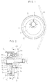
- Figs. 1 - 4 show an autotensioner used to adjust the tension of a cam shaft driving belt of an automobile engine. As shown, to one side of an engine block 1, a cylindrical support shaft 3 is fixed by tightening a bolt 2.
- a support shaft 3 has a large-diameter portion 4 at one end thereof near the engine block 1.
- On the support shaft 3 is rotatably and eccentrically supported a pulley support 6 through a bearing 5.
- the pulley support 6 comprises an eccentric ring 7 and a rocking shaft 8 secured thereto.
- the axis of the inner diameter of the eccentric ring 7 is eccentric with respect to the axis of the outer diameter thereof.
- a cylindrical portion 8a which is mounted on the large-diameter portion 4.
- the rocking shaft 8 is integrally formed at the other end with a cylindrical small-diameter portion 8b rotatably supported by the bearing 5.
- the small-diameter portion 8b is press-fitted not to rotate relative to the eccentric ring 7.
- a serration may be provided on the inner periphery of the eccentric ring 7 and/or on the outer periphery of the small-diameter portion 8b.
- a raceway groove 9 is formed in the outer periphery of the eccentric ring 7.
- An outer ring 10 is formed with a raceway groove 9a. Between the raceway grooves 9 and 10a are mounted a plurality of balls 11.
- a pulley 13 is mounted on the outer ring 10 to impart the tension to a belt 12.
- a coupling piece 14 is integrally formed on the cylindrical portion 8a of the rocking shaft 8.
- a tension adjusting spring 15 as a tension imparting means is coupled to the coupling piece 14.
- the tension adjusting spring 15 tends to rock the pulley support 6 in a direction in which the pulley 13 stretches the belt 12.
- a damper mechanism 20 to restrict a high-frequency fluctuation of the belt 12 by imparting the rocking resistance to the pulley support 6.
- the damper mechanism 20 comprises a plurality of inclined cam surfaces 21 formed on the outer periphery of the large-diameter portion 4, wedge-shaped spaces 22 defined between the cam surfaces 21 and the cylindrical inner surface of the cylindrical portion 8a, friction members 23 having the same contour as the wedge-shaped spaces 22, and springs 24 for urging the friction members 23 toward the narrower portion of each wedge-shaped space 22, the friction members 23 and the springs 24 being mounted in the wedge-shaped spaces.
- the pulley support 6 is formed so as to comprise the eccentric ring 7 and the rocking shaft 8.
- the rocking shaft 8 has a simple structure in which the cylindrical portion 8a is provided at one end thereof and the cylindrical small-diameter portion 8b is concentrically formed at the other end thereof.
- an inexpensive method such as pressing the metal plate can be employed to manufacture the rocking shaft.
- the cost can be reduced.
- Fig. 5 shows another embodiment according to the present invention.
- raceway grooves 9 and 10 are provided on the outer periphery of the eccentric ring 7 and on the inner periphery of the pulley 13, respectively.
- a plurality of balls 11 are mounted between the raceway grooves 9 and 10 so as to rotatably support the pulley.
- a space 26 sealed by a pair of seals 25.
- a viscous fluid is filled in the space 26 to form a damper mechanism 20 to impart the rocking resistance to the pulley support 6.
- the pulley support comprises an eccentric ring and a rocking shaft.
- the coupling piece for imparting a resilient force of the tension imparting means is integrally formed with a cylindrical portion of the rocking shaft.
Landscapes
- Engineering & Computer Science (AREA)
- General Engineering & Computer Science (AREA)
- Mechanical Engineering (AREA)
- Devices For Conveying Motion By Means Of Endless Flexible Members (AREA)
Claims (2)
- Selbstspanneinrichtung mit einer Trägerwelle (3), einem Riemenscheibenträger (6), der exzentrisch von der Trägerwelle (3) getragen wird, einer Riemenscheibe (13), die drehbar von dem Riemenscheibenträger (6) getragen wird, Spannmitteln (15) zum Zwängen des Riemenscheibenträgers (6) in eine Richtung, in der die Riemenscheibe (13) einen Riemen (12) streckt, wobei der Riemenscheibenträger (6) einen zylindrischen Abschnitt (8) aufweist, der konzentrisch mit der Trägerwelle ist, und Dämpfungsmittel, die zwischen dem zylindrischen Abschnitt (8a) und der Trägerwelle (3) angeordnet sind, um einen Schwenkwiderstand auf den Riemenscheibenträger (6) auszuüben,
dadurch gekennzeichnet, daß der
Riemenscheibenträger (6) einen exzentrischen Ring (7) und eine Schwenkwelle (8) aufweist, wobei der Innenumfang des exzentrischen Rings (7) bezüglich seines Außenumfangs exzentrisch ist, und daß die Schwenkwelle (8) an ihrem einen Ende mit dem zylindrischen Abschnitt (3a) versehen ist und an ihrem anderen Ende integral mit einem zylindrischen Abschnitt (8b) kleinen Durchmessers versehen ist, der in den exzentrischen Ring (7) derart eingebracht ist, daß er nicht relativ zu dem exzentrischen Ring (7) dreht. - Selbstspanneinrichtung nach Anspruch 1, wobei das Spannmittel (15) in Form einer Spannungeinstellfeder vorliegt und wobei der zylindrische Abschnitt (8a) der Schwenkwelle mit einem Kupplungsstück (14) ausgebildet ist, an das die Spannungseinstellfeder (15) gekoppelt ist.
Applications Claiming Priority (3)
| Application Number | Priority Date | Filing Date | Title |
|---|---|---|---|
| JP1992060726U JP2596625Y2 (ja) | 1992-08-28 | 1992-08-28 | オートテンショナ |
| JP60726/92U | 1992-08-28 | ||
| PCT/JP1993/001201 WO1994005932A1 (fr) | 1992-08-28 | 1993-08-26 | Tendeur automatique |
Publications (3)
| Publication Number | Publication Date |
|---|---|
| EP0609462A1 EP0609462A1 (de) | 1994-08-10 |
| EP0609462A4 EP0609462A4 (de) | 1994-10-26 |
| EP0609462B1 true EP0609462B1 (de) | 1996-12-27 |
Family
ID=13150577
Family Applications (1)
| Application Number | Title | Priority Date | Filing Date |
|---|---|---|---|
| EP93919576A Expired - Lifetime EP0609462B1 (de) | 1992-08-28 | 1993-08-26 | Automatischer spanner |
Country Status (6)
| Country | Link |
|---|---|
| US (1) | US5399124A (de) |
| EP (1) | EP0609462B1 (de) |
| JP (1) | JP2596625Y2 (de) |
| KR (1) | KR100218639B1 (de) |
| DE (1) | DE69306928T2 (de) |
| WO (1) | WO1994005932A1 (de) |
Families Citing this family (19)
| Publication number | Priority date | Publication date | Assignee | Title |
|---|---|---|---|---|
| JP2813162B2 (ja) * | 1995-04-13 | 1998-10-22 | エヌティエヌ株式会社 | オートテンショナ |
| US5759125A (en) * | 1996-06-21 | 1998-06-02 | Clark Equipment Company | Eccentrically supported tensioner |
| GB2314905A (en) * | 1996-07-03 | 1998-01-14 | Ford Motor Co | Tensioning a drive belt |
| DE19634343C2 (de) * | 1996-08-24 | 2003-01-02 | Daimler Chrysler Ag | Spanneinrichtung für Zugmittel mit festgelegtem Spannweg |
| IT1291485B1 (it) * | 1997-01-31 | 1999-01-11 | Dayco Europe Spa | Tenditore per una cinghia di trasmissione. |
| DE19739816B4 (de) * | 1997-09-11 | 2005-07-28 | Skf Gmbh | Tragkörper für Spannvorrichtungen |
| AU2707799A (en) * | 1998-03-13 | 1999-10-11 | Litens Automotive Partnership | Belt tensioner with reduced tilt action on support structure and method for installing the same |
| BR9913022A (pt) | 1998-09-18 | 2001-05-08 | Litens Automotive Inc | Tracionador de correia para tracionar uma correia para um veìculo motorizado, e, processo para instalar o mesmo |
| US6160151A (en) * | 1999-12-08 | 2000-12-12 | Nusil Technology | Process for production of diphenyl-dialkoxysilane, phenylalkyl-dialkoxysilane, octaphenylcyclotetrasilozane and sym-tetraalkyltetraphenyl-cyclotetrasiloxane |
| US6863631B2 (en) * | 2001-12-20 | 2005-03-08 | Dayco Products, Llc | Unidirectional motion asymmetric damped tensioner |
| US20030119616A1 (en) * | 2001-12-20 | 2003-06-26 | Meckstroth Richard J. | Dual friction surface asymmetric damped tensioner |
| US7229374B2 (en) * | 2001-12-20 | 2007-06-12 | Dayco Products, Llc | Dual friction surface asymmetric damped tensioner |
| DE102004058773A1 (de) * | 2004-12-07 | 2006-06-08 | Schaeffler Kg | Spannvorrichtung |
| ATE502233T1 (de) | 2005-04-20 | 2011-04-15 | Dayco Europe Srl | In gegenwart von öl arbeitende spannvorrichtung für einen riemenantrieb |
| US20060258497A1 (en) * | 2005-05-13 | 2006-11-16 | Andrzej Dec | Tensioner |
| DE102006019539A1 (de) * | 2006-04-27 | 2007-10-31 | Schaeffler Kg | Zugmitteltrieb für Maschinenteile und Antriebsaggregate |
| US8852042B2 (en) * | 2011-10-03 | 2014-10-07 | Dayco Ip Holdings, Llc | Flatwire radial asymmetric damping by coil reaction path |
| US20130095966A1 (en) * | 2011-10-17 | 2013-04-18 | GM Global Technology Operations LLC | Flexible rotary belt drive tensioner |
| JP6457222B2 (ja) * | 2014-09-04 | 2019-01-23 | Ntn株式会社 | 摩擦式オートテンショナ |
Citations (4)
| Publication number | Priority date | Publication date | Assignee | Title |
|---|---|---|---|---|
| JPS6340657U (de) * | 1986-08-30 | 1988-03-16 | ||
| JPS63303252A (ja) * | 1987-05-30 | 1988-12-09 | Koyo Seiko Co Ltd | オ−トテンシヨナ |
| JPH02445U (de) * | 1988-06-15 | 1990-01-05 | ||
| JPH04141051A (ja) * | 1990-10-01 | 1992-05-14 | Mercian Corp | 家畜用液状ビタミン剤およびその製造方法 |
Family Cites Families (5)
| Publication number | Priority date | Publication date | Assignee | Title |
|---|---|---|---|---|
| US4832665A (en) * | 1986-12-27 | 1989-05-23 | Koyo Seiko Co., Ltd. | Tensioner |
| US4923435A (en) * | 1986-12-27 | 1990-05-08 | Koyo Seiko Co., Ltd. | Chain or belt tensioner with a one-way clutch |
| GB2221279B (en) * | 1988-07-22 | 1992-07-29 | Ntn Toyo Bearing Co Ltd | Belt autotensioner |
| JPH04151051A (ja) * | 1990-10-11 | 1992-05-25 | Koyo Seiko Co Ltd | オートテンショナ |
| FR2691776B1 (fr) * | 1992-05-29 | 1994-09-16 | Ntn Toyo Bearing Co Ltd | Autotendeur. |
-
1992
- 1992-08-28 JP JP1992060726U patent/JP2596625Y2/ja not_active Expired - Fee Related
-
1993
- 1993-08-26 US US08/211,629 patent/US5399124A/en not_active Expired - Lifetime
- 1993-08-26 KR KR1019940701420A patent/KR100218639B1/ko not_active Expired - Fee Related
- 1993-08-26 WO PCT/JP1993/001201 patent/WO1994005932A1/ja not_active Ceased
- 1993-08-26 DE DE69306928T patent/DE69306928T2/de not_active Expired - Fee Related
- 1993-08-26 EP EP93919576A patent/EP0609462B1/de not_active Expired - Lifetime
Patent Citations (4)
| Publication number | Priority date | Publication date | Assignee | Title |
|---|---|---|---|---|
| JPS6340657U (de) * | 1986-08-30 | 1988-03-16 | ||
| JPS63303252A (ja) * | 1987-05-30 | 1988-12-09 | Koyo Seiko Co Ltd | オ−トテンシヨナ |
| JPH02445U (de) * | 1988-06-15 | 1990-01-05 | ||
| JPH04141051A (ja) * | 1990-10-01 | 1992-05-14 | Mercian Corp | 家畜用液状ビタミン剤およびその製造方法 |
Also Published As
| Publication number | Publication date |
|---|---|
| KR100218639B1 (ko) | 1999-09-01 |
| JP2596625Y2 (ja) | 1999-06-21 |
| EP0609462A1 (de) | 1994-08-10 |
| EP0609462A4 (de) | 1994-10-26 |
| JPH0624249U (ja) | 1994-03-29 |
| DE69306928T2 (de) | 1997-05-15 |
| WO1994005932A1 (fr) | 1994-03-17 |
| DE69306928D1 (de) | 1997-02-06 |
| US5399124A (en) | 1995-03-21 |
Similar Documents
| Publication | Publication Date | Title |
|---|---|---|
| US5399124A (en) | Autotensioner | |
| EP0362619B1 (de) | Gurtspanner | |
| US7037226B2 (en) | Dual cam surface clutch | |
| KR20110079635A (ko) | 지속 가능한 댐핑 기능을 갖는 콤팩트 텐셔너 | |
| KR930023614A (ko) | 자동텐셔너 | |
| JP3115304B2 (ja) | 斜板式のアキシアルピストン機関 | |
| GB2280724A (en) | Autotensioner for belt | |
| US4591352A (en) | Tension roller | |
| JPH10252843A (ja) | ベルト、特に歯付ベルト用の引っ張り装置 | |
| US5540627A (en) | Auto-tensioner | |
| FR2792427B1 (fr) | Dispositif de rappel au point neutre, en particulier pour volant sans axe, et volant sans axe comportant un tel dispositif | |
| JPH11107712A (ja) | 組立型中空カムシャフトの製造方法 | |
| JPH05332409A (ja) | オートテンショナ | |
| JP2596626Y2 (ja) | オートテンショナ | |
| US20030054918A1 (en) | Toroidal continuously variable transmission | |
| JP2767900B2 (ja) | オートテンショナ | |
| JPH0444139B2 (de) | ||
| JPS587856B2 (ja) | ベルトテンシヨナ− | |
| JPH053805Y2 (de) | ||
| JPH0842647A (ja) | オートテンショナ | |
| JPH053802Y2 (de) | ||
| JPH0665656U (ja) | オートテンショナ | |
| JPS6321799Y2 (de) | ||
| EP0836037B1 (de) | Automatischer Spanner | |
| JPH053801Y2 (de) |
Legal Events
| Date | Code | Title | Description |
|---|---|---|---|
| PUAI | Public reference made under article 153(3) epc to a published international application that has entered the european phase |
Free format text: ORIGINAL CODE: 0009012 |
|
| AK | Designated contracting states |
Kind code of ref document: A1 Designated state(s): DE FR GB |
|
| A4 | Supplementary search report drawn up and despatched |
Effective date: 19940909 |
|
| AK | Designated contracting states |
Kind code of ref document: A4 Designated state(s): DE FR GB |
|
| 17P | Request for examination filed |
Effective date: 19940901 |
|
| 17Q | First examination report despatched |
Effective date: 19951019 |
|
| GRAG | Despatch of communication of intention to grant |
Free format text: ORIGINAL CODE: EPIDOS AGRA |
|
| GRAH | Despatch of communication of intention to grant a patent |
Free format text: ORIGINAL CODE: EPIDOS IGRA |
|
| GRAH | Despatch of communication of intention to grant a patent |
Free format text: ORIGINAL CODE: EPIDOS IGRA |
|
| GRAA | (expected) grant |
Free format text: ORIGINAL CODE: 0009210 |
|
| AK | Designated contracting states |
Kind code of ref document: B1 Designated state(s): DE FR GB |
|
| REF | Corresponds to: |
Ref document number: 69306928 Country of ref document: DE Date of ref document: 19970206 |
|
| ET | Fr: translation filed | ||
| PLBE | No opposition filed within time limit |
Free format text: ORIGINAL CODE: 0009261 |
|
| STAA | Information on the status of an ep patent application or granted ep patent |
Free format text: STATUS: NO OPPOSITION FILED WITHIN TIME LIMIT |
|
| 26N | No opposition filed | ||
| REG | Reference to a national code |
Ref country code: GB Ref legal event code: IF02 |
|
| PGFP | Annual fee paid to national office [announced via postgrant information from national office to epo] |
Ref country code: GB Payment date: 20060823 Year of fee payment: 14 |
|
| PGFP | Annual fee paid to national office [announced via postgrant information from national office to epo] |
Ref country code: DE Payment date: 20060824 Year of fee payment: 14 |
|
| GBPC | Gb: european patent ceased through non-payment of renewal fee |
Effective date: 20070826 |
|
| PGFP | Annual fee paid to national office [announced via postgrant information from national office to epo] |
Ref country code: FR Payment date: 20070228 Year of fee payment: 14 |
|
| REG | Reference to a national code |
Ref country code: FR Ref legal event code: ST Effective date: 20080430 |
|
| PG25 | Lapsed in a contracting state [announced via postgrant information from national office to epo] |
Ref country code: DE Free format text: LAPSE BECAUSE OF NON-PAYMENT OF DUE FEES Effective date: 20080301 |
|
| PG25 | Lapsed in a contracting state [announced via postgrant information from national office to epo] |
Ref country code: FR Free format text: LAPSE BECAUSE OF NON-PAYMENT OF DUE FEES Effective date: 20070831 |
|
| PG25 | Lapsed in a contracting state [announced via postgrant information from national office to epo] |
Ref country code: GB Free format text: LAPSE BECAUSE OF NON-PAYMENT OF DUE FEES Effective date: 20070826 |